EP2235694B1 - Dispositif pour assurer la commande d'un actionneur - Google Patents
Dispositif pour assurer la commande d'un actionneur Download PDFInfo
- Publication number
- EP2235694B1 EP2235694B1 EP09702712.2A EP09702712A EP2235694B1 EP 2235694 B1 EP2235694 B1 EP 2235694B1 EP 09702712 A EP09702712 A EP 09702712A EP 2235694 B1 EP2235694 B1 EP 2235694B1
- Authority
- EP
- European Patent Office
- Prior art keywords
- actuator
- charge
- state
- energy storage
- storage device
- Prior art date
- Legal status (The legal status is an assumption and is not a legal conclusion. Google has not performed a legal analysis and makes no representation as to the accuracy of the status listed.)
- Not-in-force
Links
Images


Classifications
-
- G—PHYSICS
- G07—CHECKING-DEVICES
- G07C—TIME OR ATTENDANCE REGISTERS; REGISTERING OR INDICATING THE WORKING OF MACHINES; GENERATING RANDOM NUMBERS; VOTING OR LOTTERY APPARATUS; ARRANGEMENTS, SYSTEMS OR APPARATUS FOR CHECKING NOT PROVIDED FOR ELSEWHERE
- G07C9/00—Individual registration on entry or exit
- G07C9/00174—Electronically operated locks; Circuits therefor; Nonmechanical keys therefor, e.g. passive or active electrical keys or other data carriers without mechanical keys
- G07C9/00309—Electronically operated locks; Circuits therefor; Nonmechanical keys therefor, e.g. passive or active electrical keys or other data carriers without mechanical keys operated with bidirectional data transmission between data carrier and locks
-
- G—PHYSICS
- G07—CHECKING-DEVICES
- G07C—TIME OR ATTENDANCE REGISTERS; REGISTERING OR INDICATING THE WORKING OF MACHINES; GENERATING RANDOM NUMBERS; VOTING OR LOTTERY APPARATUS; ARRANGEMENTS, SYSTEMS OR APPARATUS FOR CHECKING NOT PROVIDED FOR ELSEWHERE
- G07C9/00—Individual registration on entry or exit
- G07C9/00174—Electronically operated locks; Circuits therefor; Nonmechanical keys therefor, e.g. passive or active electrical keys or other data carriers without mechanical keys
- G07C2009/00634—Power supply for the lock
-
- G—PHYSICS
- G07—CHECKING-DEVICES
- G07C—TIME OR ATTENDANCE REGISTERS; REGISTERING OR INDICATING THE WORKING OF MACHINES; GENERATING RANDOM NUMBERS; VOTING OR LOTTERY APPARATUS; ARRANGEMENTS, SYSTEMS OR APPARATUS FOR CHECKING NOT PROVIDED FOR ELSEWHERE
- G07C9/00—Individual registration on entry or exit
- G07C9/00174—Electronically operated locks; Circuits therefor; Nonmechanical keys therefor, e.g. passive or active electrical keys or other data carriers without mechanical keys
- G07C2009/00753—Electronically operated locks; Circuits therefor; Nonmechanical keys therefor, e.g. passive or active electrical keys or other data carriers without mechanical keys operated by active electrical keys
- G07C2009/00769—Electronically operated locks; Circuits therefor; Nonmechanical keys therefor, e.g. passive or active electrical keys or other data carriers without mechanical keys operated by active electrical keys with data transmission performed by wireless means
- G07C2009/00777—Electronically operated locks; Circuits therefor; Nonmechanical keys therefor, e.g. passive or active electrical keys or other data carriers without mechanical keys operated by active electrical keys with data transmission performed by wireless means by induction
Definitions
- the invention relates to a device for driving an actuator. Furthermore, the invention relates to a system of such a device, an actuator and a transmitting device and a transmitting device for use in such a system. Moreover, the invention relates to a method for driving an actuator.
- actuators are used for example in electronic lock cylinders, in which case the actuator may be formed as a closing magnet, which is controlled by an electronic circuit.
- the publication DE 103 48 569 A1 describes a device for driving an actuator based on a contactless communication of a transponder with a transmitting device.
- the transponder shown in this document receives control signals via an antenna device, it being possible for the transponder to trigger the actuation depending on the control signals.
- the energy transmitted via the contactless communication from the transmitting device is supplied to an energy store in the transponder.
- the energy of the energy storage is used to trigger the actuator. In this case, it may be the case that the energy store for triggering the actuator is not yet sufficiently charged when a control signal for triggering the actuator is received. In such a constellation, the actuator is not triggered by the control signal.
- US 2007/0156204 A1 shows a pacemaker to which contactless energy is transmitted.
- US 5,479,799 shows the features of the preamble of the independent claims.
- NFC Near Field Communication
- the object of the invention is to enable a contactless release of an actuator in a simple and reliable manner. This object is achieved by the combination of features of claim 1.
- the device comprises an energy store, for example in the form of a capacitor, for feeding an actuator, an antenna device with which via a contactless communication, in particular based on the NFC technology, energy from a transmitting device for charging the energy store and one or more control signals comprising a trigger command for triggering the actuator can be received, and a control unit for controlling the power supply from the energy storage to the actuator depending on the control signals.
- an energy store for example in the form of a capacitor
- an antenna device with which via a contactless communication, in particular based on the NFC technology, energy from a transmitting device for charging the energy store and one or more control signals comprising a trigger command for triggering the actuator can be received
- a control unit for controlling the power supply from the energy storage to the actuator depending on the control signals.
- the device according to the invention is designed in such a way that the state of charge of the energy store is determined during operation of the device after receipt of the trigger command, wherein a response state of the energy store, which is smaller than a sufficient state of charge threshold for triggering the actuator, a response signal to continue the contactless communication via the antenna device for reception is emitted by the transmitting device, and wherein in a state of charge of the energy storage, which is greater than or equal to the Lade gleichsschwellwert, the control device controls the energy supply from the energy storage to the actuator such that a triggering of the actuator is made possible.
- the invention is based on the idea of maintaining a contactless communication between a drive device and a transmitting device up to a charge state value of the energy store sufficient for triggering the actuated actuator, thereby ensuring triggering of the actuator, even if a sufficient state of charge of the actuator is obtained upon receipt of the trip command Energy storage has not yet reached.
- By maintaining the contactless communication of the receipt of energy to charge the energy storage is continued, so that when reaching a sufficient state of charge finally the actuator can be triggered.
- the device according to the invention has the advantage that a transmitted trip command is always suitably processed without an error message being returned due to an insufficiently charged energy store.
- the charge state threshold value sufficient for triggering the actuator can be set in such a way that it ensures the triggering of the actuator with certainty, ie the state of charge threshold value can also be above the lower limit value below which triggering of the actuator is not possible.
- the state of charge threshold may be at substantially 100% charge of the energy store.
- the state of charge threshold value of the energy store can also be set such that the actuator can not be triggered if the state of charge of the energy store is below this state of charge threshold value.
- the device is designed such that it emits an acknowledgment signal after triggering of the actuator via the antenna device for reception by the transmitting device.
- the response signal is preferably a command for extending or restarting a waiting time, which the transmitting device waits for the acknowledgment signal.
- the command to extend or to restart the waiting time can be a WTX request according to the standard ISO / IEC 14443-4.
- the use of a command to extend or restart a waiting time has the particular advantage that at the level of the transmission protocol, the waiting time and thus the contactless communication can be extended without the transmitting device special codes must be known to continue the contactless communication.
- the response signal is a special repeat command to cause the transmitter to retransmit the trip command.
- the state of charge of the energy store is determined by a state of charge measuring unit for measuring the state of charge, wherein the control unit can interrogate the state of charge of the energy store from the state of charge measurement unit preferably via a measurement data interface.
- a state-of-charge measuring unit has the advantage that information about the state of charge of the energy store can optionally also be transmitted in the response signal.
- a charging current measuring unit for measuring the charging current of the energy store is further provided, wherein information about the charging current can also be transmitted in the response signal to the transmitting device.
- the information about the state of charge or the charging current of the energy storage can be coded particularly easily by the already provided for a power-level indication bits of the WTX request.
- the control unit provided in the device according to the invention is, in a particularly preferred embodiment, an integrated circuit, in particular a chip for chip cards, whereby particularly compact dimensions of the device are achieved.
- the actuator is part of a closing device in a preferred variant, wherein the closing and opening of the closing device is triggered by the actuator.
- the invention further relates to a system comprising a transmitting device, an actuator and the above-described driving device according to the invention, wherein the actuator of the driving device by a contactlessly transmitted trip command of the transmitting device can be triggered.
- This system is preferably designed such that a triggering of the actuator can only take place after a successful authentication between the drive device and the transmitting device, so that the system can also be used for safety-critical applications.
- the system according to the invention is preferably used in combination with a drive device which uses a command to extend or restart a waiting time as a response signal for the continuation of contactless communication.
- the transmitting device sends after receiving this command a confirmation response contactlessly to the control device, which then again determines the state of charge of the energy storage, wherein in a state of charge of the energy storage, the is smaller than the Lade gleichsschwellwert, again a command for extending or restarting the waiting time via the antenna device is sent to the transmitting device, and wherein in a state of charge of the energy storage is greater than or equal to the Lade gleichsschwellwert, the control unit of the drive device for triggering the actuator, the energy supplied from the energy storage device to the actuator.
- the WTX response known from the ISO / IEC 14443-4 standard is used as confirmation response, the WTX response being transmitted by the transmitting device after receipt of the corresponding WTX request.
- the transmitting device is designed such that it emits the trigger command again in the event that a repeat command is sent out as a response signal from the control device.
- the invention further comprises a transmitting device for use in such a system, wherein the transmitting device comprises a contactlessly received response signal processing unit for continuing contactless communication, wherein the processing unit transmits an acknowledgment response in response to the response signal or the trigger command again sending out.
- the transmitting device comprises a contactlessly received response signal processing unit for continuing contactless communication, wherein the processing unit transmits an acknowledgment response in response to the response signal or the trigger command again sending out.
- the processing unit of the transmitting device can preferably process contactlessly received information about the state of charge and / or the charging current of the energy store, provided that this information is transmitted.
- the processing unit preferably comprises a signaling unit for signaling the state of charge and / or the charging current for a user.
- the signaling unit may be a display panel or a display or an acoustic signaling unit be.
- the use of such a signaling unit has the advantage that a user is informed about the current state of charge of the energy store and can read from it, how much time is needed approximately until the release of the actuator.
- a user can initiate appropriate countermeasures when displaying an insufficient charging current, for example, he can arrange the transmitting device closer to the actuator to increase the charging current.
- the processing unit can also automatically increase the transmission power of the transmitting device when the charging current falls below a predetermined value.
- the invention further comprises a method for driving an actuator with a drive device, wherein via a contactless communication from a transmitting device energy for charging an energy storage of the drive device and a trip command for triggering the actuator is transmitted to the drive device, wherein after receiving the trip command in the drive device the state of charge of the energy store is determined and, in the case of a charge state of the energy store which is smaller than a charge state threshold value sufficient for triggering the actuator, a response signal for continuation of the contactless communication is sent from the drive device to the transmission device, whereas in a state of charge of the energy store, the response is greater or equal to the state of charge threshold, the drive device connects the energy store to the actuator and thereby triggers the actuator.
- NFC Near Field Communication
- RFID Radio Frequency Identification
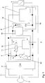
- Fig. 1 shows a schematic diagram of a transponder according to the invention.
- the structure of the transponder according to Fig. 1 corresponds in large part to the transponder in the publication DE 103 48 569 A1 is shown, wherein the entire disclosure content of this document is made by reference to the content of the present application.
- the transponder comprises a circuit arrangement 1 which is connected to an antenna device is connected in the form of an antenna coil 2. Instead of an antenna coil 2, any other suitable antenna device, such as a printed antenna, may be used.
- an actuator 3 is actuated, which is connected to the circuit arrangement 1 for this purpose.
- the actuator 3 may, for example, be a closing magnet or any other optical, acoustic, electrothermal, electrochemical, thermomechanical, electromechanical, electromagnetic, etc. device which, because of its high energy consumption or because of its high inrush current, is not fed directly by the antenna coil 2 can be.
- the circuit arrangement 1 has a rectifier 4 which is connected to the antenna coil 2 on its AC voltage side.
- the rectifier 4 is followed by a charging circuit 5 on its DC side, which can be connected on the output side via a switch 6 to a capacitor 7.
- the capacitor 7 can be connected to the actuator 3 via the switch 6.
- the switching state of the switch 6 is controlled by a transponder circuit 8, which is connected in parallel to the charging circuit.
- the transponder circuit is in particular an integrated circuit in the form of a chip card chip, e.g. a smartcard chip.
- the charging circuit 5 has a control circuit 9, which is connected to the DC side of the rectifier 4 and a first variable resistor 10 and a second variable resistor 11 controls.
- the first variable resistor 10 is connected in parallel with the DC side of the rectifier 4.
- the second variable resistor 11 connects one of the terminals of the DC side of the rectifier 4 via a diode 12 to the switch 6.
- the circuit arrangement 1 further includes a state of charge measuring unit 13, which is connected in parallel with the capacitor 7 and serves to measure the state of charge of the capacitor 7.
- the measuring device 13 is, for example, an AD converter with which the voltage across the capacitor 7 can be measured.
- a measurement data interface 15 is provided between the state of charge measurement unit 13 and the transponder circuit 8, wherein the transponder circuit can interrogate the state of charge measured by the measurement unit 13 via this interface. The measured via the measuring unit 13 state of charge is used to control the triggering of the actuator 3, as will be described in more detail below.
- a charging current measuring unit 14 is connected in series with the capacitor 7, which measures the current flowing through the capacitor charging current, wherein the measured charging current via an interface (not shown) can also be queried by the transponder circuit 8.
- the in Fig. 1 The device 2 is exposed to an alternating magnetic field in a frequency range of 13.56 MHz based on the NFC technology.
- the magnetic alternating field is generated by a transmitting device, for example, from a in Fig. 2 shown reader 21 with connected antenna 22, this reader is integrated in a mobile device 20. Due to the alternating magnetic field, a voltage is induced in the antenna coil 2, which is rectified by the rectifier 4.
- the field strength of the alternating magnetic field varies depending on the distance of the transmitting device from the antenna coil 2. In a corresponding manner also vary the induced voltage and the resulting produced rectified voltage, which serves, inter alia, the supply of the transponder circuit 8.
- the rectified voltage is regulated by the control circuit 9 to a constant preset value.
- the control circuit 9 controls the two variable resistors 10 and 11 so that the rectified voltage assumes the desired default value.
- the current Is is controlled by the control circuit 9 in each case to a value which is required for setting the rectified voltage to the desired default value. Consequently, the current Is is forcibly determined and can not be freely selected. However, the division of the current Is into the partial currents I1 and I2 can be chosen freely.
- the first controllable resistor 10 can initially be set to an infinitely high value and the second variable resistor 11 can be controlled such that the second partial current I2 corresponds to the current Is required for the regulation of the specified value for the rectified voltage.
- the second variable resistor 11 With increasing charging of the capacitor 7, the second variable resistor 11 is set to an ever smaller value. Once the second variable resistor 11 has reached its minimum value, it is also necessary to reduce the value of the first variable resistor 10 in order to keep the rectified voltage constant at the preset value hold.
- the second partial current I2 decreases and the first partial current I1 increases.
- the time required to charge the capacitor 7 can each be reduced to a minimum possible under the given conditions. How long this time actually is, depends decisively on the field strength of the alternating magnetic field in the region of the antenna coil 2, since this determines the induced voltage and thus also the current Is, which is needed to adjust the default value for the rectified voltage.
- the current Is is in turn at most available as a second partial current I2 for charging the capacitor 7. At a high field strength, only a short charging time is needed. With a low field strength, the charging process takes longer.
- a trigger command "activate actuator” is transmitted wirelessly from the transmitting device and received by the antenna device 2.
- This trip command causes the transponder circuit 8 as a rule for switching the switch 6 in a switching position in which the capacitor 7 is discharged via the actuator 3.
- a triggering of the actuator 3 takes place only when the capacitor 7 has a state sufficient for the actuation of the actuator state of charge. According to the invention, it is ensured that a continuation of the charging of the capacitor is effected via a corresponding communication between the transmitting device and the transponder in the presence of a tripping command when the capacitor is insufficiently charged, until the actuator is finally triggered when the charge is sufficient.
- a corresponding flow of such communication will be discussed below with reference to FIG Fig. 3 described.
- Fig. 2 schematically shows the communication of the transponder according to Fig. 1 with a corresponding reader 21, which is an antenna device 22 and is integrated in the mobile device 20. From the transponder is in Fig. 2 schematically reproduced the circuit arrangement 1 and the antenna device 2. Furthermore, the connection of the transponder to the actuator 3 is shown. By the double arrow P1 in Fig. 2 the non-contact NFC communication between the reader and the transponder is indicated, the communication according to the standard ISO / IEC 14443-4. In a preferred variant of the invention described below, in the communication between the transponder and the transmitting device, furthermore, the state of charge and possibly also the charging current of the capacitor 7 are transmitted to the reading device, charging state and charging current passing through the in Fig.
- the mobile device 20 further includes a security element 26 in the form of a security chip, with which a cryptographic authentication between the mobile device and the transponder is ensured, so that only authorized readers can trigger the actuator 3 via the contactless NFC communication.
- the use of the security element 26 is required in particular for safety-critical applications in which the actuator 3 is, for example, part of a locking device which is intended to be opened or closed only by authorized persons.
- Fig. 3 shows the timing of a communication according to the invention for triggering the actuator 3 based on the protocol ISO / IEC 14443-4. It is in Fig. 3 along the horizontal axis t plotted the time, above the axis t of the charge state LZ of the charge storage in the form of the capacitor 7 is reproduced in percent and shown below the time axis t the timing of the signaling between the NFC reader 21 and the transponder according to the invention is.
- the times are reproduced at which the reader emits signals and along the line L2 are reproduced the times at which the transponder emits signals.
- the times along the line L1 and L2 are represented by circles and the transmission of the signals is indicated by corresponding oblique arrows.
- a communication relationship between the transponder and the reader is initially established by the command sequence "Request ⁇ Anticollision ⁇ ATS".
- This structure of the communication relationship is in Fig. 3 schematized by a corresponding rectangle C reproduced.
- a charging current already flows into the charge storage 7, so that the state of charge of the charge storage increases steadily, as by the rising line 40 in the upper part of the Fig. 3 is indicated.
- the security element 25 described above is used. The authentication takes place via a known command sequence based on the command sequence "Get Challenge (time T1) ⁇ Set Random Number (time T2) ⁇ Authentication (time T3) ⁇ Authentication (time T4).
- the reader sends a "activate actuator” to activate the actuator to the transponder.
- This command will be sent out at time T5.
- the actuator can be triggered only when the charge accumulator is charged substantially 100%, but the command "activate actuator” is transmitted at a time at which the charge state of the charge accumulator is only about 50%.
- no activation of the actuator according to the invention in the execution of the tripping command "activate actuator” first checks the state of charge of the charge storage 7. Is the state of charge - as in Fig.
- the first transmission of this WTX request from the transponder takes place according to Fig. 3 at time T6.
- the reader confirms this WTX request with a corresponding WTX response, which is sent out at time T7.
- the Tansponder again checks whether the charge state of the charge storage device 7 is sufficient to trigger the actuator. This is in the scenario of Fig. 3 not yet the case, so that at the time T8 again a WTX request is sent to the reader, which is again answered at the time T9 by a corresponding WTX response.
- the steps of the mutual exchange of WTX requests and WTX responses are repeated until finally a 100% charge of the charge storage in the transponder is detected.
- the 100% Charge is in Fig. 3 indicated by the horizontal line 41. Furthermore, in Fig. 3 the times of mutual sending of WTX requests and WTX responses indicated by corresponding ellipses REQ and RES, which surround the timing of sending the corresponding requests or Responses. With the requests, information about the state of charge is also transmitted in the embodiment described here.
- the requests in the ellipse REQ indicate a charge state of the charge store of 60%, whereas the request sent out at time T6 indicates a charge state of 30%.
- the full charge of the capacitor is according to Fig. 3 at time Tf, whereby the full charge is detected in the transponder at time Te.
- the transponder circuit 8 then closes the switch 6 in order to supply the energy of the capacitor 7 to the actuator 3.
- a corresponding return code (eg "90 00") is sent to the reader for confirmation of the complete execution of the "activate actuator" command.
- the subsequent discharge of the capacitor is in Fig. 3 indicated by the falling edge 42.
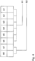
- bits 7 and 8 of the WTX request in accordance with standard ISO / IEC 14443-4, which are provided for so-called "power-level indication”.
- a possible coding of the state of charge or charging current is shown in the following table. Bit 8 Bit 7 importance 0 0 Function not supported 0 1 Charge current insufficient; Field energy too low. 1 0 Charge seperator loaded to 30% (0 .. 50%) 1 1 Charge storage 60% charged (50 .. 99%)
- bit assignments are preferably interpreted based on the above table.
- the user of the reader can be signaled that the charging current is insufficient, so that the user as a result, the antenna of the reader the battery-less actuator better aligned, thereby improving the energy transfer between the reader and the transponder.
- a corresponding signaling of an insufficient charging current or the progress of the charge of the capacitor can be carried out on the reading device, for example by an acoustic signal or a display field.
- a variant of the display of the loading progress by a bar has already been described above with reference to FIG Fig. 2 described. In this case, in addition to the progress bar or instead of the progress bar optionally also an optical display of the charging current can be done to allow the user to optimize the orientation of the antenna of the reader with respect to the transponder.
- a special return code can also be sent by the transponder instead of the WTX request.
- the information is encoded that the previously sent trigger command of the reader is not could be executed.
- the reader then sends the command "activate actuator" again, this mechanism is repeated until the charge storage is sufficiently charged and the trip command is finally executed successfully by activating the actuator analogous to the use of WTX requests and WTX responses can.
- the charge state of the charge storage device and the charging current can also be transmitted in the return code.
- the state of charge of the load memory and, where appropriate, the charging current can be signaled on the reader, for example, in turn, on the display of a mobile device in which the reader is integrated.
Landscapes
- Engineering & Computer Science (AREA)
- Computer Networks & Wireless Communication (AREA)
- Physics & Mathematics (AREA)
- General Physics & Mathematics (AREA)
- Near-Field Transmission Systems (AREA)
- Charge And Discharge Circuits For Batteries Or The Like (AREA)
Claims (16)
- Dispositif destiné au pilotage d'un actionneur (3), comprenant un réservoir d'énergie (7) destiné à l'alimentation de l'actionneur (3), un équipement d'antenne (2) avec lequel, par le biais d'une communication sans contact, en provenance d'un équipement d'émission (21), de l'énergie destinée au chargement du réservoir d'énergie (7) et un ou plusieurs signaux de commande comportant une instruction de déclenchement destinée au déclenchement de l'actionneur (3) peuvent être reçus, et une unité de commande (8) destinée à la commande de l'apport en énergie du réservoir d'énergie (7) à l'actionneur (3) en fonction des signaux de commande, caractérisé en ce que le dispositif est conçu de telle façon que, après réception de l'instruction de déclenchement, l'état de charge du réservoir d'énergie (7) est déterminé, cependant que, dans le cas d'un état de charge du réservoir d'énergie (7) inférieur à une valeur seuil d'état de charge suffisante pour le déclenchement de l'actionneur (3), un signal de réponse pour la poursuite de la communication sans contact est émis par l'intermédiaire de l'équipement d'antenne (2) pour réception par l'équipement d'émission (21), et cependant que, dans le cas d'un état de charge du réservoir d'énergie (7) supérieur ou égal à la valeur seuil d'état de charge, l'unité de commande (8) commande de telle façon l'apport en énergie du réservoir d'énergie (7) à l'actionneur (3) qu'un déclenchement de l'actionneur est rendu possible.
- Dispositif selon la revendication 1, caractérisé en ce que la communication sans contact est une communication NFC.
- Dispositif selon la revendication 1 ou 2, caractérisé en ce que la valeur seuil d'état de charge du réservoir d'énergie (7) est fixée de telle façon que l'actionneur (3) n'est pas déclenchable quand l'état de charge du réservoir d'énergie (7) est inférieur à la valeur seuil d'état de charge.
- Dispositif selon une des revendications précédentes, caractérisé en ce que le dispositif est conçu de telle façon qu'il émet un signal de confirmation après le déclenchement de l'actionneur (3) par l'intermédiaire de l'équipement d'antenne (2) pour réception par l'équipement d'émission (21).
- Dispositif selon la revendication 4, caractérisé en ce que le signal de réponse est un ordre de prolongation ou de redémarrage d'un temps d'attente du signal de confirmation attendu par l'équipement d'émission (21).
- Dispositif selon la revendication 5, caractérisé en ce que l'ordre de prolongation ou de redémarrage du temps d'attente est une requête WTX conformément à la norme ISO/IEC 14443-4.
- Dispositif selon une des revendications précédentes, caractérisé en ce que le signal de réponse est un ordre de répétition destiné à amener l'équipement d'émission (21) à émettre à nouveau l'instruction de déclenchement.
- Dispositif selon une des revendications précédentes, caractérisé en ce que le dispositif comporte une unité de mesure d'état de charge (13) destinée à la mesure de l'état de charge du réservoir d'énergie (7).
- Dispositif selon la revendication 8, caractérisé en ce que l'unité de commande (8) peut s'enquérir de l'état de charge du réservoir d'énergie (7) auprès de l'unité de mesure d'état de charge (13) par l'intermédiaire d'une interface de données de mesure (15).
- Dispositif selon la revendication 8 ou 9, caractérisé en ce que le signal de réponse comporte une information sur l'état de charge du réservoir d'énergie (7).
- Dispositif selon une des revendications précédentes, caractérisé en ce que le dispositif comprend une unité de mesure de courant de charge (14) destinée à la mesure du courant de charge du réservoir d'énergie (7).
- Dispositif selon la revendication 11, caractérisé en ce que le signal de réponse comporte une information sur le courant de charge du réservoir d'énergie (7).
- Dispositif selon une des revendications précédentes en combinaison avec la revendication 6 et la revendication 10 ou 12, caractérisé en ce que les bits de la requête WTX prévus pour l'indication du niveau de puissance contiennent l'information sur l'état de charge du réservoir d'énergie (7) et/ou sur le courant de charge du réservoir d'énergie (7).
- Dispositif selon une des revendications précédentes, caractérisé en ce que l'actionneur (8) fait partie d'un équipement de fermeture.
- Système comprenant un équipement d'émission (21), un actionneur (3) et un dispositif de pilotage (1, 2) destiné au pilotage d'un actionneur (3), cependant que l'actionneur (3) peut être déclenché par le dispositif de pilotage (1, 2) au moyen d'une instruction de déclenchement, transmise sans contact, provenant de équipement d'émission (21), caractérisé en ce que le dispositif de pilotage (1, 2) est réalisé conformément à une des revendications précédentes.
- Procédé destiné au pilotage d'un actionneur (3), comprenant un dispositif de pilotage (1, 2), cependant que, par l'intermédiaire d'une communication sans contact, par un équipement d'émission (21), de l'énergie destinée au chargement d'un réservoir d'énergie (7) du dispositif de pilotage (1, 2) et une instruction de déclenchement destinée au déclenchement de l'actionneur (3) est transmise au dispositif de pilotage (1, 2), caractérisé en ce que, après réception de l'instruction de déclenchement dans le dispositif de pilotage (1, 2), l'état de charge du réservoir d'énergie (7) est déterminé, cependant que, dans le cas d'un état de charge du réservoir d'énergie (7) inférieur à une valeur seuil d'état de charge suffisante pour le déclenchement de l'actionneur (3), un signal de réponse pour la poursuite de la communication sans contact est émis par le dispositif de pilotage (1, 2) pour réception par l'équipement d'émission (21), et cependant que, dans le cas d'un état de charge du réservoir d'énergie (7) supérieur ou égal à la valeur seuil d'état de charge, le dispositif de pilotage (1, 2) connecte le réservoir d'énergie (7) à l'actionneur (3) et déclenche ainsi l'actionneur (3).
Applications Claiming Priority (2)
| Application Number | Priority Date | Filing Date | Title |
|---|---|---|---|
| DE102008005059A DE102008005059A1 (de) | 2008-01-18 | 2008-01-18 | Vorrichtung zum Ansteuern eines Aktuators |
| PCT/EP2009/050474 WO2009090235A2 (fr) | 2008-01-18 | 2009-01-16 | Dispositif pour assurer la commande d'un actionneur |
Publications (2)
| Publication Number | Publication Date |
|---|---|
| EP2235694A2 EP2235694A2 (fr) | 2010-10-06 |
| EP2235694B1 true EP2235694B1 (fr) | 2018-05-16 |
Family
ID=40785872
Family Applications (1)
| Application Number | Title | Priority Date | Filing Date |
|---|---|---|---|
| EP09702712.2A Not-in-force EP2235694B1 (fr) | 2008-01-18 | 2009-01-16 | Dispositif pour assurer la commande d'un actionneur |
Country Status (4)
| Country | Link |
|---|---|
| US (1) | US8482377B2 (fr) |
| EP (1) | EP2235694B1 (fr) |
| DE (1) | DE102008005059A1 (fr) |
| WO (1) | WO2009090235A2 (fr) |
Families Citing this family (10)
| Publication number | Priority date | Publication date | Assignee | Title |
|---|---|---|---|---|
| FR2945162A1 (fr) * | 2009-04-30 | 2010-11-05 | Pascal Metivier | Systeme d'alimentation externe d'une serrure comportant des moyens de communication sans contact de type nfc |
| KR20140144174A (ko) * | 2012-01-05 | 2014-12-18 | 아닥 플라스틱스 인코포레이티드 | 차량 접근 시스템 |
| FR2987475B1 (fr) * | 2012-02-24 | 2016-07-08 | Stmicroelectronics Rousset | Recharge d'un dispositif nfc |
| GB2501729A (en) * | 2012-05-02 | 2013-11-06 | Itso Ltd | Ticketing system using NFC tags and portable user device |
| ES2769873T3 (es) * | 2013-03-22 | 2020-06-29 | Utc Fire & Security Americas | Cerradura electrónica con fuentes de potencia seleccionables |
| US9732977B2 (en) | 2014-09-02 | 2017-08-15 | Johnson Controls Technology Company | Systems and methods for configuring and communicating with HVAC devices |
| US10291292B2 (en) | 2014-09-02 | 2019-05-14 | Johnson Controls Technology Company | Wireless sensor with near field communication circuit |
| US9500006B2 (en) * | 2014-09-24 | 2016-11-22 | Vemus Endustriyel Elektronik Sanayi Ve Ticaret Limited Sirketi | Easily managed electronic cabinet lock |
| US10326497B2 (en) * | 2017-04-11 | 2019-06-18 | Honeywell International Inc. | Expansion modules with switches and external communication |
| CA3087386A1 (fr) | 2019-07-18 | 2021-01-18 | Endura Products, Llc | Procedes d'actionnement d'une serrure |
Family Cites Families (9)
| Publication number | Priority date | Publication date | Assignee | Title |
|---|---|---|---|---|
| US5479799A (en) * | 1994-10-27 | 1996-01-02 | Kilman Electriloc Company | Key and bolt lock device |
| US5591217A (en) | 1995-01-04 | 1997-01-07 | Plexus, Inc. | Implantable stimulator with replenishable, high value capacitive power source and method therefor |
| EP1666087A3 (fr) | 1997-02-26 | 2009-04-29 | The Alfred E Mann Foundation for Scientific Research | Dispositif implantable sur un patient et fonctionnant sur batterie |
| EP1056510B1 (fr) | 1998-02-23 | 2005-05-11 | Medtronic, Inc. | Dispositif medical implantable a couplage rf, dote d'une source d'alimentation de secours rechargeable |
| FI20002493A7 (fi) | 2000-11-14 | 2002-05-15 | Salcomp Oy | Teholähdejärjestely ja induktiivisesti kytketty akkulaturi, jossa on langattomasti kytketty ohjaus, ja menetelmä teholähdejärjestelyn ja induktiivisesti kytketyn akkulaturin ohjaamiseksi langattomasti |
| DE10348569A1 (de) | 2003-10-20 | 2005-05-25 | Giesecke & Devrient Gmbh | Vorrichtung zum Ansteuern eines Aktuators |
| DE102004036358B4 (de) | 2004-07-27 | 2016-11-03 | Giesecke & Devrient Gmbh | Dosiervorrichtung |
| DE102004039650A1 (de) | 2004-08-16 | 2006-03-09 | Giesecke & Devrient Gmbh | Flexibles kontaktloses Aufladen eines Akkumulators |
| US7720547B2 (en) * | 2006-01-04 | 2010-05-18 | Kenergy, Inc. | Extracorporeal power supply with a wireless feedback system for an implanted medical device |
-
2008
- 2008-01-18 DE DE102008005059A patent/DE102008005059A1/de not_active Withdrawn
-
2009
- 2009-01-16 US US12/735,437 patent/US8482377B2/en not_active Expired - Fee Related
- 2009-01-16 EP EP09702712.2A patent/EP2235694B1/fr not_active Not-in-force
- 2009-01-16 WO PCT/EP2009/050474 patent/WO2009090235A2/fr not_active Ceased
Non-Patent Citations (1)
| Title |
|---|
| None * |
Also Published As
| Publication number | Publication date |
|---|---|
| DE102008005059A1 (de) | 2009-07-23 |
| US20100308957A1 (en) | 2010-12-09 |
| WO2009090235A3 (fr) | 2009-09-17 |
| WO2009090235A2 (fr) | 2009-07-23 |
| EP2235694A2 (fr) | 2010-10-06 |
| US8482377B2 (en) | 2013-07-09 |
Similar Documents
| Publication | Publication Date | Title |
|---|---|---|
| EP2235694B1 (fr) | Dispositif pour assurer la commande d'un actionneur | |
| EP2483831B1 (fr) | Lecteur rfid, système rfid, procédé de régulation de la puissance d'émission d'un lecteur rfid et produit de programme informatique | |
| EP1376460B1 (fr) | Carte à puce | |
| DE69518678T2 (de) | Tragbare Vorrichtung für funktionelle Verbindung zwischen einer IC-Karte und einer Zentraleinheit | |
| EP1973055B1 (fr) | Unité de lecture et méthode pour détection à faible énergie d'un transpondeur | |
| EP2132721B1 (fr) | Dispositif pour commander un actionneur | |
| EP2446400B1 (fr) | Lecteur et systeme rfid | |
| EP2256662B1 (fr) | Procédé de détection de supports d'identification | |
| DE112006002666T5 (de) | Mittel zum Deaktivieren einer kontaktlosen Vorrichtung | |
| DE4329697A1 (de) | Fernsteuerbare Zugangskontrolleinrichtung | |
| DE69926286T2 (de) | Kartenleser/-schreiber und Kommunikationsverfahren | |
| DE102005061660A1 (de) | Tragbarer Datenträger mit aktiver Kontaktlosschnittstelle | |
| EP1678684B1 (fr) | Dispositif pour commander un actionneur | |
| WO2019030334A1 (fr) | Émetteur d'identification mobile | |
| WO2019030340A1 (fr) | Émetteur d'identification mobile | |
| EP3396640B1 (fr) | Émetteur d'identification portable pour un système d'authentification et procédé de fonctionnement d'un système d'authentification | |
| DE102014216987B4 (de) | Schlüsselloses System und mobile Vorrichtung | |
| EP3582148A1 (fr) | Document pourvu de moyens de détection | |
| EP1723615B1 (fr) | Composant inductif pour cle electronique | |
| DE10348569A1 (de) | Vorrichtung zum Ansteuern eines Aktuators | |
| DE102015222235B4 (de) | Tragbare Vorrichtung und Verfahren zum Aktivieren oder Deaktivieren eines Kraftfahrzeugs | |
| DE102016218618A1 (de) | Vorrichtung und Verfahren zur Zugangs- und Startverifizierung in einem Fahrzeug | |
| EP3259700B1 (fr) | Lecteur de carte sans contact | |
| DE19617251C2 (de) | Datenübertragungssystem | |
| DE10208478A1 (de) | Kommunikationsgerät mit induktiver Eingabeeinrichtung |
Legal Events
| Date | Code | Title | Description |
|---|---|---|---|
| PUAI | Public reference made under article 153(3) epc to a published international application that has entered the european phase |
Free format text: ORIGINAL CODE: 0009012 |
|
| 17P | Request for examination filed |
Effective date: 20100818 |
|
| AK | Designated contracting states |
Kind code of ref document: A2 Designated state(s): AT BE BG CH CY CZ DE DK EE ES FI FR GB GR HR HU IE IS IT LI LT LU LV MC MK MT NL NO PL PT RO SE SI SK TR |
|
| AX | Request for extension of the european patent |
Extension state: AL BA RS |
|
| DAX | Request for extension of the european patent (deleted) | ||
| STAA | Information on the status of an ep patent application or granted ep patent |
Free format text: STATUS: EXAMINATION IS IN PROGRESS |
|
| 17Q | First examination report despatched |
Effective date: 20170130 |
|
| RAP1 | Party data changed (applicant data changed or rights of an application transferred) |
Owner name: GIESECKE+DEVRIENT MOBILE SECURITY GMBH |
|
| GRAP | Despatch of communication of intention to grant a patent |
Free format text: ORIGINAL CODE: EPIDOSNIGR1 |
|
| STAA | Information on the status of an ep patent application or granted ep patent |
Free format text: STATUS: GRANT OF PATENT IS INTENDED |
|
| INTG | Intention to grant announced |
Effective date: 20171206 |
|
| GRAS | Grant fee paid |
Free format text: ORIGINAL CODE: EPIDOSNIGR3 |
|
| GRAA | (expected) grant |
Free format text: ORIGINAL CODE: 0009210 |
|
| STAA | Information on the status of an ep patent application or granted ep patent |
Free format text: STATUS: THE PATENT HAS BEEN GRANTED |
|
| AK | Designated contracting states |
Kind code of ref document: B1 Designated state(s): AT BE BG CH CY CZ DE DK EE ES FI FR GB GR HR HU IE IS IT LI LT LU LV MC MK MT NL NO PL PT RO SE SI SK TR |
|
| REG | Reference to a national code |
Ref country code: GB Ref legal event code: FG4D Free format text: NOT ENGLISH |
|
| REG | Reference to a national code |
Ref country code: CH Ref legal event code: EP |
|
| REG | Reference to a national code |
Ref country code: DE Ref legal event code: R096 Ref document number: 502009014961 Country of ref document: DE |
|
| REG | Reference to a national code |
Ref country code: IE Ref legal event code: FG4D Free format text: LANGUAGE OF EP DOCUMENT: GERMAN |
|
| REG | Reference to a national code |
Ref country code: AT Ref legal event code: REF Ref document number: 1000237 Country of ref document: AT Kind code of ref document: T Effective date: 20180615 |
|
| REG | Reference to a national code |
Ref country code: SE Ref legal event code: TRGR |
|
| REG | Reference to a national code |
Ref country code: NL Ref legal event code: MP Effective date: 20180516 |
|
| REG | Reference to a national code |
Ref country code: LT Ref legal event code: MG4D |
|
| PG25 | Lapsed in a contracting state [announced via postgrant information from national office to epo] |
Ref country code: ES Free format text: LAPSE BECAUSE OF FAILURE TO SUBMIT A TRANSLATION OF THE DESCRIPTION OR TO PAY THE FEE WITHIN THE PRESCRIBED TIME-LIMIT Effective date: 20180516 Ref country code: LT Free format text: LAPSE BECAUSE OF FAILURE TO SUBMIT A TRANSLATION OF THE DESCRIPTION OR TO PAY THE FEE WITHIN THE PRESCRIBED TIME-LIMIT Effective date: 20180516 Ref country code: NO Free format text: LAPSE BECAUSE OF FAILURE TO SUBMIT A TRANSLATION OF THE DESCRIPTION OR TO PAY THE FEE WITHIN THE PRESCRIBED TIME-LIMIT Effective date: 20180816 Ref country code: BG Free format text: LAPSE BECAUSE OF FAILURE TO SUBMIT A TRANSLATION OF THE DESCRIPTION OR TO PAY THE FEE WITHIN THE PRESCRIBED TIME-LIMIT Effective date: 20180816 Ref country code: FI Free format text: LAPSE BECAUSE OF FAILURE TO SUBMIT A TRANSLATION OF THE DESCRIPTION OR TO PAY THE FEE WITHIN THE PRESCRIBED TIME-LIMIT Effective date: 20180516 |
|
| PG25 | Lapsed in a contracting state [announced via postgrant information from national office to epo] |
Ref country code: LV Free format text: LAPSE BECAUSE OF FAILURE TO SUBMIT A TRANSLATION OF THE DESCRIPTION OR TO PAY THE FEE WITHIN THE PRESCRIBED TIME-LIMIT Effective date: 20180516 Ref country code: NL Free format text: LAPSE BECAUSE OF FAILURE TO SUBMIT A TRANSLATION OF THE DESCRIPTION OR TO PAY THE FEE WITHIN THE PRESCRIBED TIME-LIMIT Effective date: 20180516 Ref country code: HR Free format text: LAPSE BECAUSE OF FAILURE TO SUBMIT A TRANSLATION OF THE DESCRIPTION OR TO PAY THE FEE WITHIN THE PRESCRIBED TIME-LIMIT Effective date: 20180516 Ref country code: GR Free format text: LAPSE BECAUSE OF FAILURE TO SUBMIT A TRANSLATION OF THE DESCRIPTION OR TO PAY THE FEE WITHIN THE PRESCRIBED TIME-LIMIT Effective date: 20180817 |
|
| PG25 | Lapsed in a contracting state [announced via postgrant information from national office to epo] |
Ref country code: SK Free format text: LAPSE BECAUSE OF FAILURE TO SUBMIT A TRANSLATION OF THE DESCRIPTION OR TO PAY THE FEE WITHIN THE PRESCRIBED TIME-LIMIT Effective date: 20180516 Ref country code: DK Free format text: LAPSE BECAUSE OF FAILURE TO SUBMIT A TRANSLATION OF THE DESCRIPTION OR TO PAY THE FEE WITHIN THE PRESCRIBED TIME-LIMIT Effective date: 20180516 Ref country code: EE Free format text: LAPSE BECAUSE OF FAILURE TO SUBMIT A TRANSLATION OF THE DESCRIPTION OR TO PAY THE FEE WITHIN THE PRESCRIBED TIME-LIMIT Effective date: 20180516 Ref country code: PL Free format text: LAPSE BECAUSE OF FAILURE TO SUBMIT A TRANSLATION OF THE DESCRIPTION OR TO PAY THE FEE WITHIN THE PRESCRIBED TIME-LIMIT Effective date: 20180516 Ref country code: RO Free format text: LAPSE BECAUSE OF FAILURE TO SUBMIT A TRANSLATION OF THE DESCRIPTION OR TO PAY THE FEE WITHIN THE PRESCRIBED TIME-LIMIT Effective date: 20180516 Ref country code: CZ Free format text: LAPSE BECAUSE OF FAILURE TO SUBMIT A TRANSLATION OF THE DESCRIPTION OR TO PAY THE FEE WITHIN THE PRESCRIBED TIME-LIMIT Effective date: 20180516 |
|
| REG | Reference to a national code |
Ref country code: DE Ref legal event code: R097 Ref document number: 502009014961 Country of ref document: DE |
|
| PG25 | Lapsed in a contracting state [announced via postgrant information from national office to epo] |
Ref country code: IT Free format text: LAPSE BECAUSE OF FAILURE TO SUBMIT A TRANSLATION OF THE DESCRIPTION OR TO PAY THE FEE WITHIN THE PRESCRIBED TIME-LIMIT Effective date: 20180516 |
|
| PLBE | No opposition filed within time limit |
Free format text: ORIGINAL CODE: 0009261 |
|
| STAA | Information on the status of an ep patent application or granted ep patent |
Free format text: STATUS: NO OPPOSITION FILED WITHIN TIME LIMIT |
|
| 26N | No opposition filed |
Effective date: 20190219 |
|
| PG25 | Lapsed in a contracting state [announced via postgrant information from national office to epo] |
Ref country code: SI Free format text: LAPSE BECAUSE OF FAILURE TO SUBMIT A TRANSLATION OF THE DESCRIPTION OR TO PAY THE FEE WITHIN THE PRESCRIBED TIME-LIMIT Effective date: 20180516 |
|
| PG25 | Lapsed in a contracting state [announced via postgrant information from national office to epo] |
Ref country code: MC Free format text: LAPSE BECAUSE OF FAILURE TO SUBMIT A TRANSLATION OF THE DESCRIPTION OR TO PAY THE FEE WITHIN THE PRESCRIBED TIME-LIMIT Effective date: 20180516 |
|
| PG25 | Lapsed in a contracting state [announced via postgrant information from national office to epo] |
Ref country code: LU Free format text: LAPSE BECAUSE OF NON-PAYMENT OF DUE FEES Effective date: 20190116 |
|
| REG | Reference to a national code |
Ref country code: BE Ref legal event code: MM Effective date: 20190131 |
|
| REG | Reference to a national code |
Ref country code: IE Ref legal event code: MM4A |
|
| PG25 | Lapsed in a contracting state [announced via postgrant information from national office to epo] |
Ref country code: BE Free format text: LAPSE BECAUSE OF NON-PAYMENT OF DUE FEES Effective date: 20190131 |
|
| PG25 | Lapsed in a contracting state [announced via postgrant information from national office to epo] |
Ref country code: IE Free format text: LAPSE BECAUSE OF NON-PAYMENT OF DUE FEES Effective date: 20190116 |
|
| PG25 | Lapsed in a contracting state [announced via postgrant information from national office to epo] |
Ref country code: TR Free format text: LAPSE BECAUSE OF FAILURE TO SUBMIT A TRANSLATION OF THE DESCRIPTION OR TO PAY THE FEE WITHIN THE PRESCRIBED TIME-LIMIT Effective date: 20180516 |
|
| PG25 | Lapsed in a contracting state [announced via postgrant information from national office to epo] |
Ref country code: PT Free format text: LAPSE BECAUSE OF FAILURE TO SUBMIT A TRANSLATION OF THE DESCRIPTION OR TO PAY THE FEE WITHIN THE PRESCRIBED TIME-LIMIT Effective date: 20180917 Ref country code: MT Free format text: LAPSE BECAUSE OF FAILURE TO SUBMIT A TRANSLATION OF THE DESCRIPTION OR TO PAY THE FEE WITHIN THE PRESCRIBED TIME-LIMIT Effective date: 20180516 |
|
| PGFP | Annual fee paid to national office [announced via postgrant information from national office to epo] |
Ref country code: FR Payment date: 20210121 Year of fee payment: 13 Ref country code: CH Payment date: 20210122 Year of fee payment: 13 |
|
| PG25 | Lapsed in a contracting state [announced via postgrant information from national office to epo] |
Ref country code: CY Free format text: LAPSE BECAUSE OF FAILURE TO SUBMIT A TRANSLATION OF THE DESCRIPTION OR TO PAY THE FEE WITHIN THE PRESCRIBED TIME-LIMIT Effective date: 20180516 |
|
| PGFP | Annual fee paid to national office [announced via postgrant information from national office to epo] |
Ref country code: AT Payment date: 20210119 Year of fee payment: 13 Ref country code: GB Payment date: 20210122 Year of fee payment: 13 Ref country code: SE Payment date: 20210122 Year of fee payment: 13 Ref country code: DE Payment date: 20210131 Year of fee payment: 13 |
|
| PG25 | Lapsed in a contracting state [announced via postgrant information from national office to epo] |
Ref country code: IS Free format text: LAPSE BECAUSE OF FAILURE TO SUBMIT A TRANSLATION OF THE DESCRIPTION OR TO PAY THE FEE WITHIN THE PRESCRIBED TIME-LIMIT Effective date: 20180916 |
|
| PG25 | Lapsed in a contracting state [announced via postgrant information from national office to epo] |
Ref country code: HU Free format text: LAPSE BECAUSE OF FAILURE TO SUBMIT A TRANSLATION OF THE DESCRIPTION OR TO PAY THE FEE WITHIN THE PRESCRIBED TIME-LIMIT; INVALID AB INITIO Effective date: 20090116 |
|
| PG25 | Lapsed in a contracting state [announced via postgrant information from national office to epo] |
Ref country code: MK Free format text: LAPSE BECAUSE OF FAILURE TO SUBMIT A TRANSLATION OF THE DESCRIPTION OR TO PAY THE FEE WITHIN THE PRESCRIBED TIME-LIMIT Effective date: 20180516 |
|
| REG | Reference to a national code |
Ref country code: DE Ref legal event code: R119 Ref document number: 502009014961 Country of ref document: DE |
|
| REG | Reference to a national code |
Ref country code: SE Ref legal event code: EUG |
|
| REG | Reference to a national code |
Ref country code: CH Ref legal event code: PL |
|
| REG | Reference to a national code |
Ref country code: AT Ref legal event code: MM01 Ref document number: 1000237 Country of ref document: AT Kind code of ref document: T Effective date: 20220116 |
|
| GBPC | Gb: european patent ceased through non-payment of renewal fee |
Effective date: 20220116 |
|
| PG25 | Lapsed in a contracting state [announced via postgrant information from national office to epo] |
Ref country code: SE Free format text: LAPSE BECAUSE OF NON-PAYMENT OF DUE FEES Effective date: 20220117 Ref country code: GB Free format text: LAPSE BECAUSE OF NON-PAYMENT OF DUE FEES Effective date: 20220116 Ref country code: DE Free format text: LAPSE BECAUSE OF NON-PAYMENT OF DUE FEES Effective date: 20220802 Ref country code: AT Free format text: LAPSE BECAUSE OF NON-PAYMENT OF DUE FEES Effective date: 20220116 |
|
| PG25 | Lapsed in a contracting state [announced via postgrant information from national office to epo] |
Ref country code: FR Free format text: LAPSE BECAUSE OF NON-PAYMENT OF DUE FEES Effective date: 20220131 |
|
| PG25 | Lapsed in a contracting state [announced via postgrant information from national office to epo] |
Ref country code: LI Free format text: LAPSE BECAUSE OF NON-PAYMENT OF DUE FEES Effective date: 20220131 Ref country code: CH Free format text: LAPSE BECAUSE OF NON-PAYMENT OF DUE FEES Effective date: 20220131 |