EP2236213A2 - Dispositif de sortie - Google Patents
Dispositif de sortie Download PDFInfo
- Publication number
- EP2236213A2 EP2236213A2 EP10003038A EP10003038A EP2236213A2 EP 2236213 A2 EP2236213 A2 EP 2236213A2 EP 10003038 A EP10003038 A EP 10003038A EP 10003038 A EP10003038 A EP 10003038A EP 2236213 A2 EP2236213 A2 EP 2236213A2
- Authority
- EP
- European Patent Office
- Prior art keywords
- media
- discharge
- discharge device
- housing
- metering chamber
- Prior art date
- Legal status (The legal status is an assumption and is not a legal conclusion. Google has not performed a legal analysis and makes no representation as to the accuracy of the status listed.)
- Granted
Links
Images


Classifications
-
- B—PERFORMING OPERATIONS; TRANSPORTING
- B05—SPRAYING OR ATOMISING IN GENERAL; APPLYING FLUENT MATERIALS TO SURFACES, IN GENERAL
- B05B—SPRAYING APPARATUS; ATOMISING APPARATUS; NOZZLES
- B05B11/00—Single-unit hand-held apparatus in which flow of contents is produced by the muscular force of the operator at the moment of use
- B05B11/0005—Components or details
- B05B11/0062—Outlet valves actuated by the pressure of the fluid to be sprayed
- B05B11/0064—Lift valves
- B05B11/0067—Lift valves having a valve seat located downstream the valve element
-
- B—PERFORMING OPERATIONS; TRANSPORTING
- B05—SPRAYING OR ATOMISING IN GENERAL; APPLYING FLUENT MATERIALS TO SURFACES, IN GENERAL
- B05B—SPRAYING APPARATUS; ATOMISING APPARATUS; NOZZLES
- B05B11/00—Single-unit hand-held apparatus in which flow of contents is produced by the muscular force of the operator at the moment of use
- B05B11/01—Single-unit hand-held apparatus in which flow of contents is produced by the muscular force of the operator at the moment of use characterised by the means producing the flow
- B05B11/02—Membranes or pistons acting on the contents inside the container, e.g. follower pistons
- B05B11/026—Membranes separating the content remaining in the container from the atmospheric air to compensate underpressure inside the container
-
- B—PERFORMING OPERATIONS; TRANSPORTING
- B05—SPRAYING OR ATOMISING IN GENERAL; APPLYING FLUENT MATERIALS TO SURFACES, IN GENERAL
- B05B—SPRAYING APPARATUS; ATOMISING APPARATUS; NOZZLES
- B05B11/00—Single-unit hand-held apparatus in which flow of contents is produced by the muscular force of the operator at the moment of use
- B05B11/01—Single-unit hand-held apparatus in which flow of contents is produced by the muscular force of the operator at the moment of use characterised by the means producing the flow
- B05B11/10—Pump arrangements for transferring the contents from the container to a pump chamber by a sucking effect and forcing the contents out through the dispensing nozzle
- B05B11/1001—Piston pumps
- B05B11/1004—Piston pumps comprising a movable cylinder and a stationary piston
-
- B—PERFORMING OPERATIONS; TRANSPORTING
- B05—SPRAYING OR ATOMISING IN GENERAL; APPLYING FLUENT MATERIALS TO SURFACES, IN GENERAL
- B05B—SPRAYING APPARATUS; ATOMISING APPARATUS; NOZZLES
- B05B11/00—Single-unit hand-held apparatus in which flow of contents is produced by the muscular force of the operator at the moment of use
- B05B11/01—Single-unit hand-held apparatus in which flow of contents is produced by the muscular force of the operator at the moment of use characterised by the means producing the flow
- B05B11/10—Pump arrangements for transferring the contents from the container to a pump chamber by a sucking effect and forcing the contents out through the dispensing nozzle
- B05B11/1042—Components or details
- B05B11/1066—Pump inlet valves
- B05B11/107—Gate valves; Sliding valves
Definitions
- the invention relates to a discharge device for liquid media, in particular for pharmaceutical media, with two along a total stroke between an unactuated rest position and an actuated end position against each other movable housing sections which together form an actuator for manual Austragbetuschist, with a media storage for storage of the medium before discharge and with a conveyor having a discharge opening and a metering chamber.
- the actuator and the conveyor are operatively coupled in generic dispensing devices that during a outgoing from the rest position of the first part of the Austragbetuschist the media storage and metering are in communicating connection and that during a subsequent to the first partial stroke second Operahubs the discharge of the media storage and the metering device are separated from each other, wherein the volume of the metering chamber is reduced by the second partial stroke of the discharge operation, then that the medium is pressed out of the metering chamber to the discharge opening.
- Such a generic discharge device is for example from the EP 1 606 192 B1 known.
- the object of the invention is to develop a generic discharge device with regard to a simplified and / or preservative-free drug-suitable structure and with regard to improved functionality.
- the media reservoir to be operatively coupled to the actuating device such that a discharge actuation of the actuating device simultaneously effects a volume reduction of the media reservoir.
- the housing sections provided according to the invention are understood to mean two parts of the discharge device which are at least partially accessible to a user from the outside and which are movable relative to one another.
- the housing sections may be integrally formed or composed of a plurality of interconnected components.
- the housing sections are designed to be moved against each other as intended in order to effect a discharge process. Preferably, therefore, they each have finger bearing surfaces, which simplify manual handling.
- the housing sections are preferably displaceable relative to one another in translation in the direction of a linear actuation direction, wherein the actuation direction is preferably aligned in such a way that the housing sections are displaced towards one another during a discharge process.
- the housing sections form an actuating device, by means of which the conveyor can be actuated.
- This conveyor has a metering chamber, which is separated in the course of the relative movement of the housing sections of the media storage, so that a subsequent reduction of the volume of the metering in the course of continued relative movement of the housing sections does not cause the medium from the metering chamber flows back into the media storage , Instead, the volume reduction of the metering chamber after separation from the media storage leads to a discharge process, since the medium can only escape from the metering chamber in the direction of the discharge opening.
- the actuating device is designed such that it not only causes the separation of the metering chamber from the media reservoir and the subsequent discharge process.
- the actuator is additionally operatively coupled to the media storage, so that the manual discharge operation simultaneously with the discharge process also causes a volume reduction of the media storage.
- the active coupling between the actuating device and the media reservoir can be designed such that the volume reduction of the media reservoir is effected during the first partial stroke or during the second partial stroke.
- Particularly advantageous is a design in which takes place during the first and during the second partial stroke, a reduction of the media storage volume.
- This volume reduction of the media storage means that an overpressure forms in the media storage, which due to the active coupling with the actuator a force of Casing sections in the direction of the rest position causes.
- the standing under this pressure medium and the standing in this pressure air in the media storage thus act during the Austragbetuschist as a kind of air spring pushes the housing sections back towards the rest position after completion of the discharge and after elimination of manual application of force to the discharge.
- This air spring can thereby have a significant share in the provision of the discharge.
- an additional spring element in particular a metallic return spring. This waiver of a metallic spring in contact with media is particularly advantageous for preservative-free media.
- the media storage can for this purpose be completely isolated from the environment or allow only an air inlet. It is also possible to use an air filter between the environment and the media storage, which allows only a small amount of air leakage.
- Such an air filter is preferably designed to permit an air outlet of not more than 10 ml / min, preferably of not more than 6 ml / min, at an overpressure of 2 bar in the media reservoir. Such a small leakage of air from the media storage does not affect the air spring function to a relevant extent.
- the interaction between the actuating device and the media reservoir is preferably effected by a direct mechanical coupling, for example by the relative position of the housing sections relative to each other directly to the displacement of walls of the media storage leads.
- the media reservoir is not completely filled with the medium already in a delivery state of the discharge device, so that sufficient air is present in the media reservoir in order to ensure the described air spring function.
- the amount of media in the media reservoir is preferably such that the medium has not more than 90%, in particular not more than 80%, of the volume of the volume-reduced media reservoir in the end position of the housing sections.
- the volume of the medium reservoir in the rest position is a maximum of 50 ml, more preferably between 2 ml and 10 ml. These volumes are usually sufficient for the intended purpose, the use for pharmaceutical media.
- active coupling of the media store with the media store is preferably designed such that the volume of the media store is reduced by at least 10% during the total stroke consisting of the first and the second partial stroke.
- the volume reduction is at least 15%, more preferably at least 20%.
- the discharge device is designed and / or filled with medium, that a reduction of the medium contained in the media storage and / or the air contained in the media storage causes a reduced spacing of the two housing sections in the rest position.
- the media reservoir is connected to an environment only indirectly via the metering chamber and that an outlet valve is provided between the metering chamber and the outlet opening, which prevents an inflow of air into the metering chamber through the outlet opening. Consequently, the discharged during a discharge medium can not be replaced by air in the media storage. Instead, the total amount of media and air in the media reservoir continuously decreases over the life of the dispenser.
- Said outlet valve is preferably designed as a pressure-dependent switching outlet valve, which opens during the discharge due to the increased media pressure in the metering chamber and which automatically closes during the return stroke, so that no air can flow in this way in the media storage.
- return spring means of the discharge device are designed to be sufficiently weak that they do not cause complete resetting against the negative pressure arising in the media reservoir due to the reduced amount of media. Instead, the aforementioned balance of power and thus the Sleep mode with a smaller volume of media storage. As a result of the active coupling of the media reservoir with the actuating device, this volume reduction of the media reservoir also leads to a rest position of the housing sections which changes with each discharge process.
- a scale or an indicator is preferably provided in a contact region of the housing sections.
- a design with a continuous color transition or with a tapered symbol, for example a printed triangle is therefore also possible, for example.
- the housing sections are formed such that one of the housing sections is inserted into a recess of the other housing section, wherein the scale is advantageously mounted in this case on the intended supraschiebenden housing section and thus makes the Einschiebetiefe easily detectable.
- the media storage is preferably designed for the purpose of interaction with the actuating device such that it is partially bounded by a first wall which is stationary relative to the first housing section, and partially by a second wall is limited, which is stationary to the second housing.
- the displacement of the housing sections relative to each other also directly effects a displacement of the first and the second wall of the media reservoir relative to each other.
- the media reservoir is partially bounded by a third wall which is formed by a shape-changeable intermediate component which is fastened to the first housing section and to the second housing section.
- This form variable intermediate component which forms the third wall, is in particular preferably circumferentially sealingly connected to the first housing portion on the one hand and the second housing portion on the other.
- the intermediate component is designed to be elastic and the housing sections are acted upon in the end position by a force which presses the housing sections in the direction of the rest position.
- the intermediate member thus not only assumes an advantageous sealing function, but also takes over a spring function by being elastically stretched or compressed during the transfer of the housing sections from the rest position to the end position and the energy absorbed thereby in the return of the housing sections in their rest position End of the discharge process again.
- the intermediate element is designed as a bellows, preferably as a bellows which is open on both sides and whose open sides are circumferentially connected to the first housing section and the second housing section.
- the design as a bellows offers some significant advantages.
- the bellows has a largely defined expansion and compression direction, so that the reduction of the amount of media and / or air in the media storage and the concomitant reduction of the media storage volume in the rest position leads to a defined position of the housing sections to each other in this rest position.
- the above-described spring function of the intermediate element is achieved by the bellows in a simple manner.
- the bellows is preferably aligned in the discharge device such that its component-related compression direction coincides with the actuation direction of the discharge device, that is, with the direction of displacement of the housing sections relative to one another.
- the bellows can be designed such that it is open only in the direction of the metering chamber and is closed in the opposite direction.
- the media reservoir comprises a cavity in the first and a cavity in the second housing portion, wherein the volume surrounded by the bellows a Volume variable third part of the media storage forms.
- the actuating direction and the conveying device are operatively coupled such that at a first partial stroke there is a connection between the media reservoir and the metering chamber and a separation of the metering chamber from the media reservoir and a subsequent volume reduction of the following in a subsequent rectified second partial stroke Dosing takes place.
- the metering chamber is formed by a provided in one of the housing portions cavity, which is open in the direction of the other housing portion, wherein on the other housing portion a piston portion is provided which during the operation in the transition from the first partial stroke to the second partial stroke an edge of the cavity comes into contact all around and thereby separates the dosing chamber from the media storage.
- the piston portion is preferably fixedly attached to the housing portion to which it is assigned.
- the cavity is still connected to the metering chamber.
- the metering chamber formed thereby is subsequently reduced in volume by a continued displacement of the piston portion and its associated housing portion relative to the housing portion with the metering chamber cavity to thereby induce the discharge operation.
- the metering chamber is preferably arranged relative to the media storage such that the medium from the media storage in the presence of a communicating connection between the metering chamber and the media storage flows into the metering chamber due to its weight.
- the metering chamber is therefore arranged under the media reservoir or at least below the liquid level of the medium in the media storage. This arrangement below the media storage refers to a proper discharge position of the discharge.
- a nasal dispenser is, for example, a layer in which the discharge opening points approximately or exactly upwards.
- the medium can also be sucked into the metering chamber by means of a negative pressure forming in the metering chamber after the medium has left the medium.
- a negative pressure forming in the metering chamber is particularly advantageous.
- the two housing sections are guided by direct contact contact relative to each other movable.
- a guide which can be formed for example by nested cylindrical sections of the two housing sections, the actuation direction is defined.
- the subsections which form the guide are preferably not part of the wall of the media reservoir, so that it is possible to dispense with a liquid-tight seal between them.
- the first housing section comprises the discharge opening and the second housing section comprises an underbody of the discharge device.
- a finger rest is preferably provided on the first housing section beyond.
- On the second housing section can be dispensed with such a dedicated finger rest, because instead of the underbody can be used as a second finger rest.
- a discharge device is provided in particular for filling with a pharmaceutical medium.
- a pharmaceutical medium in particular, it can be used for nasal, oral, ophthalmic or topical applications.
- the outlet port is preferably provided on a conical nosepiece dimensioned to be insertable into a nostril of a user.
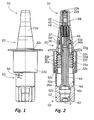
- the Fig. 1 and 2 show a discharge device 10 according to the invention in an initial state.
- the discharge device 10 has two mutually movable housing sections 20, 50.
- the upper housing section 20 has an outer component 22, which comprises a nose olive 22a with a discharge opening 22b introduced therein. Furthermore, the outer component 22 has a finger rest 22c which adjoins the nose olive 22b at the bottom and extends radially outwards. From this finger rest 22c, a cylindrical guide collar 22d extends downward.
- an inner member 24 is inserted, which is fixedly connected by means of a positive coupling with the outer part 22 and which always remains stationary during operation to the outer member 22.
- This inner component 24, which is arranged for the most part within the nose olive 22a, on the one hand forms the basis for a pressure-controlled outlet valve 40.
- This outlet valve 40 has a valve body 42 which is pressed against the outlet opening 22b by means of a valve spring 44 supported on the inner component 24.
- a downwardly facing coupling ring 24a is formed, in which a piston member 26 is inserted.
- This Piston component 26 assumes a fixed relative to the inner member 24 and thus also to the outer member 22 a fixed and operating immutable relative position.
- the actual piston portion 26a is provided, whose operation will be explained below.
- the lower housing portion 50 is formed by a one-piece component 52 which is formed in a hollow cylindrical portion 52a. Below this middle section 52a, the free inner area tapers through a series of steps. The lower end of the inner region of the component 52 forms a cavity 52b, the function of which will be described below. At the middle portion 52a of the component 52 is followed at the upper end of a further hollow cylindrical portion 52c with increased inner and outer diameter.
- the two housing sections 20, 50 are designed to be movable toward one another in the direction of an actuating axis 2.
- the guide collar 22 d of the upper housing portion 20 and the cylindrical portion 52 c of the lower housing portion 50 are adapted to each other in diameter so that they together form a guide that allows relative movement of the housing portions 20, 50 only in the direction of the axis 2.
- the section 52c with the enlarged outer diameter is inserted for this purpose in the guide collar 22d and prevented by unspecified locking means 22e from being pulled out of this again.
- a bellows 30 is provided, which is mounted in inaccessible from the outside position.
- This bellows 30 is open at its both ends and has respective cylindrical coupling portions 30a, 30b at its ends.
- the Lower coupling portion 30a is in the assembled state in the Fig. 2 apparent manner inserted into the central portion 52 a of the component 52.
- the upper coupling section 30b is pushed onto a circumferential coupling web 22f of the component 22.
- the coupling portions 30a, 30b are fitted to the respective contact portions 52a, 22f so as to provide liquid-tight joints.
- the bellows is formed integrally with the component 22 or the component 52, wherein the elastic deformability of the bellows can be achieved in this case, for example via a correspondingly adapted wall thickness of the bellows.
- the described media-carrying regions are formed by the housing sections and components described: An inner cavity 60a, which is formed by an inner wall 22g, the outer component 22 and the inner component 24, an adjoining region 60b, which is formed by the inner region of the bellows 30, and a region 60c surrounded on the outside by the cylindrical middle section 52a and the stepped region of the component 52 adjoining below together form a media reservoir 60.
- the already described cavity 52b in the component 52 forms a metering chamber 62 adjoining the media reservoir 60 at the lower end
- the media reservoir 60 and the metering chamber 62 form a uniform large chamber and thus the liquid exchange is readily possible, a separation of the metering chamber 62 is made from the media reservoir 60 in the form described below during the operation.
- a liquid channel 64 extends through the piston member 26 upwards. This liquid channel 64 is at its upper end in a liquid passage 66 within the Inner component 24 via. Between the inner component 24 and the outer component 22 there is a narrow annular gap which forms a pressure chamber 68 adjoining the channel 66. From the overpressure of the medium within this pressure chamber 68, it depends on whether the exhaust valve 40 is open or closed.
- Fig. 3a shows the initial state of the donor before its first use.
- the media spaces and channels 64, 66, 68 are already filled with media at this time. This filling can be done in the course of production or can be effected by the user by means of a first discharge operation.
- Fig. 3a How out Fig. 3a is apparent, moreover, the media reservoir 60 and the associated therewith dosing chamber 62 are also filled with the medium, wherein in Fig. 3 It can be clearly seen that the media reservoir 60 is only partially filled with liquid. The liquid-free upper region of the media reservoir 60 is filled with air.
- the discharge device 10 is in the state of Fig. 3a in the rest position and therefore not burdened by a force applied manually from the outside. Due to the spring action of the bellows 30, the housing sections 20, 50 in this initial state of Fig. 3a sufficiently energized to assume their illustrated maximum spaced condition.
- a manual application of force to the discharge device 10 wherein a
- a preferably user puts his index finger and middle finger on the finger rest 22c and hangs up his thumb on the underbody 52d.
- the housing sections 20, 50 are displaced toward one another, so that the lower housing section 50 engages deeper into the recess of the upper housing section 20 formed by the guide collar 22d. This takes place with simultaneous compression of the bellows 30.
- the volume reduction of the media reservoir 60, in particular of the region 60b of the media reservoir 60, is possible because the media reservoir 60 is partially filled in the manner described with compressible air.
- the compression of the housing sections 20, 50 initially leads to the intermediate state of Fig.
- the illustrated discharge device 10 has no air inlet into the media reservoir 60, so that the total amount of the medium and the air in the media reservoir 60 is continuously reduced over the lifetime of the discharge device.
- this leads to the distance between the housing sections 20, 50 in the idle state, that is to say in the absence of an external application of force, being reduced with each discharge process.
- the bellows 30 is specifically designed for this purpose so that the spring force caused by it is not sufficient to after the dispensing of parts of the medium against the negative pressure generated in the media reservoir 60, the housing sections 20, 50 back to the starting position of the Fig. 1, 2 and 3a to convict.
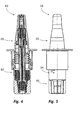
- the 4 and 5 show the discharge device 10 after five Discharge processes in the changed resting position.
- the change in the quiescent state caused by these discharge processes can be clearly recognized on the scale 54 on the outside of the lower housing section 50.
- the scale indicates a level of 100%.
- the scale indicates a remaining level of about 50% as a result of the changed resting position. It is therefore very easy to see how full the media storage of the discharge device 10 is still.
- the functioning of the discharge device 10 is not affected by the change in the rest position, since it is only significant for the functioning that the piston section 26a loses contact with the edge of the cavity 52b during the return stroke so that the medium can flow into the dosing chamber 62.
- the described discharge device 10 is intended for nasal applications.
- alternative designs for other applications are conceivable, such as a design for a donor to be used orally.
- the nasal olive instead of the nasal olive, therefore, other designs of the outlet region can be provided, in which the discharge direction does not have to coincide with the actuation direction, but can include with it, for example, an angle of 90 °.
Landscapes
- Containers And Packaging Bodies Having A Special Means To Remove Contents (AREA)
- Infusion, Injection, And Reservoir Apparatuses (AREA)
Applications Claiming Priority (1)
| Application Number | Priority Date | Filing Date | Title |
|---|---|---|---|
| DE102009017459.1A DE102009017459B4 (de) | 2009-04-02 | 2009-04-02 | Austragvorrichtung |
Publications (3)
| Publication Number | Publication Date |
|---|---|
| EP2236213A2 true EP2236213A2 (fr) | 2010-10-06 |
| EP2236213A3 EP2236213A3 (fr) | 2011-11-23 |
| EP2236213B1 EP2236213B1 (fr) | 2013-05-01 |
Family
ID=42288842
Family Applications (1)
| Application Number | Title | Priority Date | Filing Date |
|---|---|---|---|
| EP10003038.6A Active EP2236213B1 (fr) | 2009-04-02 | 2010-03-23 | Dispositif de sortie |
Country Status (3)
| Country | Link |
|---|---|
| US (1) | US8348096B2 (fr) |
| EP (1) | EP2236213B1 (fr) |
| DE (1) | DE102009017459B4 (fr) |
Cited By (1)
| Publication number | Priority date | Publication date | Assignee | Title |
|---|---|---|---|---|
| EP4368227A1 (fr) * | 2022-11-09 | 2024-05-15 | Aptar Radolfzell GmbH | Distributeur de liquide pour application nasale et dispositif de pompage |
Families Citing this family (17)
| Publication number | Priority date | Publication date | Assignee | Title |
|---|---|---|---|---|
| DE102010045059A1 (de) * | 2010-09-10 | 2012-03-15 | F. Holzer Gmbh | Dosiervorrichtung |
| US8939943B2 (en) | 2011-01-26 | 2015-01-27 | Kaleo, Inc. | Medicament delivery device for administration of opioid antagonists including formulations for naloxone |
| US8627816B2 (en) | 2011-02-28 | 2014-01-14 | Intelliject, Inc. | Medicament delivery device for administration of opioid antagonists including formulations for naloxone |
| GB2489216B (en) * | 2011-03-16 | 2013-08-07 | Consort Medical Plc | Fluid delivery device |
| DE102011106261A1 (de) * | 2011-05-18 | 2012-11-22 | Meadwestvaco Calmar Gmbh | Spender zur dosierten Abgabe von flüssigen Medien |
| GB201117518D0 (en) | 2011-10-11 | 2011-11-23 | Consort Medical Plc | Fluid delivery device |
| GB2516434B (en) | 2013-07-19 | 2015-11-25 | Consort Medical Plc | Fluid delivery device |
| DE102013220492A1 (de) * | 2013-10-10 | 2015-04-16 | Aptar Radolfzell Gmbh | Kindergesicherte Austragvorrichtung |
| US9517307B2 (en) | 2014-07-18 | 2016-12-13 | Kaleo, Inc. | Devices and methods for delivering opioid antagonists including formulations for naloxone |
| EP3558420B1 (fr) | 2016-12-23 | 2024-09-18 | Kaleo, Inc. | Dispositif d'administration de médicament et procédés d'administration de médicaments à des nourrissons et des enfants |
| KR102015622B1 (ko) * | 2018-02-05 | 2019-08-28 | (주)연우 | 유체 용기 |
| DE102018208110A1 (de) * | 2018-05-23 | 2019-11-28 | F. Holzer Gmbh | Abgabekopf und Abgabevorrichtung zur dosierten Abgabe flüssiger Präparate sowie Verwendungsmöglichkeiten |
| DE102018216060A1 (de) * | 2018-09-20 | 2020-03-26 | F. Holzer Gmbh | Pumpkopf sowie Dosiervorrichtung |
| US11420810B1 (en) * | 2020-09-11 | 2022-08-23 | Robert Wise | Refillable solution dispensing device |
| DE102022000980A1 (de) * | 2022-03-22 | 2023-09-28 | Frank Matanic | Dosiervorrichtung |
| USD1071732S1 (en) * | 2023-01-30 | 2025-04-22 | Aptar Radolfzell Gmbh | Fluid dispenser |
| DE102023109238A1 (de) | 2023-04-12 | 2024-10-17 | Frank Matanic | Von Hand betätigbare Vorrichtung zum portionierten Austragen einer Flüssigkeit |
Citations (1)
| Publication number | Priority date | Publication date | Assignee | Title |
|---|---|---|---|---|
| EP1606192B1 (fr) | 2003-03-27 | 2007-10-17 | Rexam Dispensing Systems | Distributeur de produit comprenant une pompe mise en oeuvre par un piston |
Family Cites Families (19)
| Publication number | Priority date | Publication date | Assignee | Title |
|---|---|---|---|---|
| US1810135A (en) * | 1929-02-04 | 1931-06-16 | Fred W Fitch | Cream dispenser |
| US1930872A (en) * | 1930-03-08 | 1933-10-17 | Clyde W Blackmun | Perfume atomizer |
| US1926367A (en) * | 1931-06-05 | 1933-09-12 | Booth John Bertram | Liquid and semiliquid container |
| US3185345A (en) * | 1963-01-24 | 1965-05-25 | Gillette Co | Dispensing container with contents indicator |
| US3878973A (en) * | 1973-10-31 | 1975-04-22 | Ciba Geigy Corp | Metered dose dispenser |
| US4098434A (en) * | 1975-06-20 | 1978-07-04 | Owens-Illinois, Inc. | Fluid product dispenser |
| US4177939A (en) * | 1977-07-22 | 1979-12-11 | Bristol-Myers Company | Squeeze bottle |
| US4413757A (en) * | 1981-03-09 | 1983-11-08 | Adler Harold A | Dispenser for repelling animals |
| DE8522082U1 (de) * | 1985-07-31 | 1985-10-24 | Frankenwald-Presserei Horst Rebhan, 8647 Stockheim | Spender aus Kunsstoff zur portionsweisen Abgabe von Flüssigkeiten |
| DE8526339U1 (de) * | 1985-09-14 | 1987-05-07 | Ing. Erich Pfeiffer GmbH & Co KG, 7760 Radolfzell | Austragvorrichtung für fließfähige Medien |
| DE3712802C1 (en) * | 1987-04-15 | 1988-06-23 | Hertrampf Michael | Liquid dispenser, in particular for toothpaste |
| US5353961A (en) * | 1993-01-15 | 1994-10-11 | Reseal International Limited Partnership | Dual chamber dispenser |
| US5366120A (en) * | 1994-04-19 | 1994-11-22 | Tonis Tollasepp | Paint pump |
| JP3563014B2 (ja) * | 2000-06-26 | 2004-09-08 | 株式会社トップ | 吐出容器 |
| FR2811640B1 (fr) * | 2000-07-17 | 2002-12-27 | Oreal | Dispositif de conditionnement et de distribution permettant de distribuer une dose variable |
| DE50006973D1 (de) | 2000-10-19 | 2004-08-05 | Dentaco Gmbh | Dosierspender für fliessfähige Medien mit einer in einem Medienbehälter integrierten, handbetätigbaren Pumpe |
| US6991137B2 (en) * | 2001-05-23 | 2006-01-31 | Ben Zane Cohen | Accurate dosing pump |
| US7437930B2 (en) * | 2003-12-17 | 2008-10-21 | L'oreal | Assembly comprising a dispensing device and a case which makes it possible to know the degree of emptying of the dispensing device |
| GB2422786B (en) * | 2005-03-03 | 2007-05-23 | Bespak Plc | Dispenser |
-
2009
- 2009-04-02 DE DE102009017459.1A patent/DE102009017459B4/de not_active Expired - Fee Related
-
2010
- 2010-03-23 EP EP10003038.6A patent/EP2236213B1/fr active Active
- 2010-04-02 US US12/798,407 patent/US8348096B2/en not_active Expired - Fee Related
Patent Citations (1)
| Publication number | Priority date | Publication date | Assignee | Title |
|---|---|---|---|---|
| EP1606192B1 (fr) | 2003-03-27 | 2007-10-17 | Rexam Dispensing Systems | Distributeur de produit comprenant une pompe mise en oeuvre par un piston |
Cited By (1)
| Publication number | Priority date | Publication date | Assignee | Title |
|---|---|---|---|---|
| EP4368227A1 (fr) * | 2022-11-09 | 2024-05-15 | Aptar Radolfzell GmbH | Distributeur de liquide pour application nasale et dispositif de pompage |
Also Published As
| Publication number | Publication date |
|---|---|
| US8348096B2 (en) | 2013-01-08 |
| EP2236213A3 (fr) | 2011-11-23 |
| EP2236213B1 (fr) | 2013-05-01 |
| DE102009017459A1 (de) | 2010-10-07 |
| DE102009017459B4 (de) | 2017-02-23 |
| US20100252581A1 (en) | 2010-10-07 |
Similar Documents
| Publication | Publication Date | Title |
|---|---|---|
| EP2236213B1 (fr) | Dispositif de sortie | |
| DE69803361T2 (de) | Vorrichtung zur abgabe vom fliessfähigen produkt mit verschlussvorrichtung | |
| EP2753433B1 (fr) | Distributeur de liquide | |
| DE69507979T2 (de) | Abgabepumpe | |
| EP2804504B1 (fr) | Distributeur de fluides | |
| EP3094416B1 (fr) | Distributeur pour liquides | |
| DE69919321T2 (de) | Zerstäubungskopf für einen spender für medien | |
| DE3315334A1 (de) | Zerstaeuber- oder dosierpumpe | |
| EP2200752A1 (fr) | Dispositif de dosage | |
| EP1834704A2 (fr) | Distributeur de produit fluide | |
| EP3079834B1 (fr) | Distributeur | |
| DE60118233T2 (de) | Ausgabekopf zur ausgabe einer flüssigkeit und spender mit einem solchen kopf | |
| EP3427840B1 (fr) | Distributeur de liquide | |
| DE102016212892C5 (de) | Pumpkopf sowie Dosiervorrichtung | |
| DE602004005613T2 (de) | Pumpe zur abgabe eines fluidprodukts | |
| EP3275555A1 (fr) | Distributeur de liquide, en particulier inhalateur | |
| WO2014128007A1 (fr) | Dispositif de distribution à l'épreuve des enfants | |
| EP1616630A2 (fr) | Distributeur de produit fluide | |
| EP3736049A1 (fr) | Tête distributrice et distributeur de liquide comprenant une tête distributrice | |
| DE3525449C2 (de) | Ausgabe-Einrichtung für fließfähige Medien | |
| EP1616631A2 (fr) | Distributeur doseur de fluides | |
| EP2383045B1 (fr) | Dispositif de distribution de liquides | |
| DE60301572T2 (de) | Abgabepumpe für medien | |
| WO2019141713A1 (fr) | Dispositif de dosage de liquides | |
| EP4401889A1 (fr) | Dispositif de distribution de portions d'un milieu liquide |
Legal Events
| Date | Code | Title | Description |
|---|---|---|---|
| PUAI | Public reference made under article 153(3) epc to a published international application that has entered the european phase |
Free format text: ORIGINAL CODE: 0009012 |
|
| AK | Designated contracting states |
Kind code of ref document: A2 Designated state(s): AT BE BG CH CY CZ DE DK EE ES FI FR GB GR HR HU IE IS IT LI LT LU LV MC MK MT NL NO PL PT RO SE SI SK SM TR |
|
| AX | Request for extension of the european patent |
Extension state: AL BA ME RS |
|
| PUAL | Search report despatched |
Free format text: ORIGINAL CODE: 0009013 |
|
| AK | Designated contracting states |
Kind code of ref document: A3 Designated state(s): AT BE BG CH CY CZ DE DK EE ES FI FR GB GR HR HU IE IS IT LI LT LU LV MC MK MT NL NO PL PT RO SE SI SK SM TR |
|
| AX | Request for extension of the european patent |
Extension state: AL BA ME RS |
|
| RIC1 | Information provided on ipc code assigned before grant |
Ipc: B05B 11/00 20060101AFI20111020BHEP |
|
| 17P | Request for examination filed |
Effective date: 20120224 |
|
| GRAP | Despatch of communication of intention to grant a patent |
Free format text: ORIGINAL CODE: EPIDOSNIGR1 |
|
| RAP1 | Party data changed (applicant data changed or rights of an application transferred) |
Owner name: APTAR RADOLFZELL GMBH |
|
| GRAS | Grant fee paid |
Free format text: ORIGINAL CODE: EPIDOSNIGR3 |
|
| GRAP | Despatch of communication of intention to grant a patent |
Free format text: ORIGINAL CODE: EPIDOSNIGR1 |
|
| GRAA | (expected) grant |
Free format text: ORIGINAL CODE: 0009210 |
|
| AK | Designated contracting states |
Kind code of ref document: B1 Designated state(s): AT BE BG CH CY CZ DE DK EE ES FI FR GB GR HR HU IE IS IT LI LT LU LV MC MK MT NL NO PL PT RO SE SI SK SM TR |
|
| REG | Reference to a national code |
Ref country code: GB Ref legal event code: FG4D Free format text: NOT ENGLISH |
|
| REG | Reference to a national code |
Ref country code: CH Ref legal event code: EP Ref country code: AT Ref legal event code: REF Ref document number: 609556 Country of ref document: AT Kind code of ref document: T Effective date: 20130515 |
|
| REG | Reference to a national code |
Ref country code: IE Ref legal event code: FG4D Free format text: LANGUAGE OF EP DOCUMENT: GERMAN |
|
| REG | Reference to a national code |
Ref country code: DE Ref legal event code: R096 Ref document number: 502010003104 Country of ref document: DE Effective date: 20130627 |
|
| REG | Reference to a national code |
Ref country code: CH Ref legal event code: NV Representative=s name: WAGNER PATENT AG, CH |
|
| REG | Reference to a national code |
Ref country code: NL Ref legal event code: VDEP Effective date: 20130501 |
|
| REG | Reference to a national code |
Ref country code: LT Ref legal event code: MG4D |
|
| PG25 | Lapsed in a contracting state [announced via postgrant information from national office to epo] |
Ref country code: PT Free format text: LAPSE BECAUSE OF FAILURE TO SUBMIT A TRANSLATION OF THE DESCRIPTION OR TO PAY THE FEE WITHIN THE PRESCRIBED TIME-LIMIT Effective date: 20130902 Ref country code: NO Free format text: LAPSE BECAUSE OF FAILURE TO SUBMIT A TRANSLATION OF THE DESCRIPTION OR TO PAY THE FEE WITHIN THE PRESCRIBED TIME-LIMIT Effective date: 20130801 Ref country code: SE Free format text: LAPSE BECAUSE OF FAILURE TO SUBMIT A TRANSLATION OF THE DESCRIPTION OR TO PAY THE FEE WITHIN THE PRESCRIBED TIME-LIMIT Effective date: 20130501 Ref country code: GR Free format text: LAPSE BECAUSE OF FAILURE TO SUBMIT A TRANSLATION OF THE DESCRIPTION OR TO PAY THE FEE WITHIN THE PRESCRIBED TIME-LIMIT Effective date: 20130802 Ref country code: LT Free format text: LAPSE BECAUSE OF FAILURE TO SUBMIT A TRANSLATION OF THE DESCRIPTION OR TO PAY THE FEE WITHIN THE PRESCRIBED TIME-LIMIT Effective date: 20130501 Ref country code: IS Free format text: LAPSE BECAUSE OF FAILURE TO SUBMIT A TRANSLATION OF THE DESCRIPTION OR TO PAY THE FEE WITHIN THE PRESCRIBED TIME-LIMIT Effective date: 20130901 Ref country code: SI Free format text: LAPSE BECAUSE OF FAILURE TO SUBMIT A TRANSLATION OF THE DESCRIPTION OR TO PAY THE FEE WITHIN THE PRESCRIBED TIME-LIMIT Effective date: 20130501 Ref country code: ES Free format text: LAPSE BECAUSE OF FAILURE TO SUBMIT A TRANSLATION OF THE DESCRIPTION OR TO PAY THE FEE WITHIN THE PRESCRIBED TIME-LIMIT Effective date: 20130812 Ref country code: FI Free format text: LAPSE BECAUSE OF FAILURE TO SUBMIT A TRANSLATION OF THE DESCRIPTION OR TO PAY THE FEE WITHIN THE PRESCRIBED TIME-LIMIT Effective date: 20130501 |
|
| PG25 | Lapsed in a contracting state [announced via postgrant information from national office to epo] |
Ref country code: HR Free format text: LAPSE BECAUSE OF FAILURE TO SUBMIT A TRANSLATION OF THE DESCRIPTION OR TO PAY THE FEE WITHIN THE PRESCRIBED TIME-LIMIT Effective date: 20130501 Ref country code: CY Free format text: LAPSE BECAUSE OF FAILURE TO SUBMIT A TRANSLATION OF THE DESCRIPTION OR TO PAY THE FEE WITHIN THE PRESCRIBED TIME-LIMIT Effective date: 20130501 Ref country code: BG Free format text: LAPSE BECAUSE OF FAILURE TO SUBMIT A TRANSLATION OF THE DESCRIPTION OR TO PAY THE FEE WITHIN THE PRESCRIBED TIME-LIMIT Effective date: 20130801 Ref country code: PL Free format text: LAPSE BECAUSE OF FAILURE TO SUBMIT A TRANSLATION OF THE DESCRIPTION OR TO PAY THE FEE WITHIN THE PRESCRIBED TIME-LIMIT Effective date: 20130501 |
|
| PG25 | Lapsed in a contracting state [announced via postgrant information from national office to epo] |
Ref country code: LV Free format text: LAPSE BECAUSE OF FAILURE TO SUBMIT A TRANSLATION OF THE DESCRIPTION OR TO PAY THE FEE WITHIN THE PRESCRIBED TIME-LIMIT Effective date: 20130501 |
|
| PG25 | Lapsed in a contracting state [announced via postgrant information from national office to epo] |
Ref country code: CZ Free format text: LAPSE BECAUSE OF FAILURE TO SUBMIT A TRANSLATION OF THE DESCRIPTION OR TO PAY THE FEE WITHIN THE PRESCRIBED TIME-LIMIT Effective date: 20130501 Ref country code: DK Free format text: LAPSE BECAUSE OF FAILURE TO SUBMIT A TRANSLATION OF THE DESCRIPTION OR TO PAY THE FEE WITHIN THE PRESCRIBED TIME-LIMIT Effective date: 20130501 Ref country code: SK Free format text: LAPSE BECAUSE OF FAILURE TO SUBMIT A TRANSLATION OF THE DESCRIPTION OR TO PAY THE FEE WITHIN THE PRESCRIBED TIME-LIMIT Effective date: 20130501 Ref country code: EE Free format text: LAPSE BECAUSE OF FAILURE TO SUBMIT A TRANSLATION OF THE DESCRIPTION OR TO PAY THE FEE WITHIN THE PRESCRIBED TIME-LIMIT Effective date: 20130501 |
|
| PG25 | Lapsed in a contracting state [announced via postgrant information from national office to epo] |
Ref country code: RO Free format text: LAPSE BECAUSE OF FAILURE TO SUBMIT A TRANSLATION OF THE DESCRIPTION OR TO PAY THE FEE WITHIN THE PRESCRIBED TIME-LIMIT Effective date: 20130501 Ref country code: NL Free format text: LAPSE BECAUSE OF FAILURE TO SUBMIT A TRANSLATION OF THE DESCRIPTION OR TO PAY THE FEE WITHIN THE PRESCRIBED TIME-LIMIT Effective date: 20130501 |
|
| PLBE | No opposition filed within time limit |
Free format text: ORIGINAL CODE: 0009261 |
|
| STAA | Information on the status of an ep patent application or granted ep patent |
Free format text: STATUS: NO OPPOSITION FILED WITHIN TIME LIMIT |
|
| REG | Reference to a national code |
Ref country code: CH Ref legal event code: PCAR Free format text: NEW ADDRESS: BAECHERSTRASSE 9, 8832 WOLLERAU (CH) |
|
| 26N | No opposition filed |
Effective date: 20140204 |
|
| REG | Reference to a national code |
Ref country code: DE Ref legal event code: R097 Ref document number: 502010003104 Country of ref document: DE Effective date: 20140204 |
|
| PG25 | Lapsed in a contracting state [announced via postgrant information from national office to epo] |
Ref country code: LU Free format text: LAPSE BECAUSE OF FAILURE TO SUBMIT A TRANSLATION OF THE DESCRIPTION OR TO PAY THE FEE WITHIN THE PRESCRIBED TIME-LIMIT Effective date: 20140323 |
|
| REG | Reference to a national code |
Ref country code: CH Ref legal event code: PL |
|
| REG | Reference to a national code |
Ref country code: IE Ref legal event code: MM4A |
|
| PG25 | Lapsed in a contracting state [announced via postgrant information from national office to epo] |
Ref country code: CH Free format text: LAPSE BECAUSE OF NON-PAYMENT OF DUE FEES Effective date: 20140331 Ref country code: LI Free format text: LAPSE BECAUSE OF NON-PAYMENT OF DUE FEES Effective date: 20140331 Ref country code: IE Free format text: LAPSE BECAUSE OF NON-PAYMENT OF DUE FEES Effective date: 20140323 |
|
| PG25 | Lapsed in a contracting state [announced via postgrant information from national office to epo] |
Ref country code: IT Free format text: LAPSE BECAUSE OF NON-PAYMENT OF DUE FEES Effective date: 20140323 |
|
| REG | Reference to a national code |
Ref country code: DE Ref legal event code: R082 Ref document number: 502010003104 Country of ref document: DE Representative=s name: WITTE, WELLER & PARTNER PATENTANWAELTE MBB, DE Ref country code: DE Ref legal event code: R082 Ref document number: 502010003104 Country of ref document: DE Representative=s name: PATENTANWALTSKANZLEI CARTAGENA PARTNERSCHAFTSG, DE |
|
| PG25 | Lapsed in a contracting state [announced via postgrant information from national office to epo] |
Ref country code: MT Free format text: LAPSE BECAUSE OF FAILURE TO SUBMIT A TRANSLATION OF THE DESCRIPTION OR TO PAY THE FEE WITHIN THE PRESCRIBED TIME-LIMIT Effective date: 20130501 |
|
| REG | Reference to a national code |
Ref country code: FR Ref legal event code: PLFP Year of fee payment: 7 |
|
| PG25 | Lapsed in a contracting state [announced via postgrant information from national office to epo] |
Ref country code: SM Free format text: LAPSE BECAUSE OF FAILURE TO SUBMIT A TRANSLATION OF THE DESCRIPTION OR TO PAY THE FEE WITHIN THE PRESCRIBED TIME-LIMIT Effective date: 20130501 |
|
| REG | Reference to a national code |
Ref country code: AT Ref legal event code: MM01 Ref document number: 609556 Country of ref document: AT Kind code of ref document: T Effective date: 20150323 |
|
| PG25 | Lapsed in a contracting state [announced via postgrant information from national office to epo] |
Ref country code: MC Free format text: LAPSE BECAUSE OF FAILURE TO SUBMIT A TRANSLATION OF THE DESCRIPTION OR TO PAY THE FEE WITHIN THE PRESCRIBED TIME-LIMIT Effective date: 20130501 |
|
| PGFP | Annual fee paid to national office [announced via postgrant information from national office to epo] |
Ref country code: GB Payment date: 20160322 Year of fee payment: 7 Ref country code: FR Payment date: 20160322 Year of fee payment: 7 |
|
| PG25 | Lapsed in a contracting state [announced via postgrant information from national office to epo] |
Ref country code: HU Free format text: LAPSE BECAUSE OF FAILURE TO SUBMIT A TRANSLATION OF THE DESCRIPTION OR TO PAY THE FEE WITHIN THE PRESCRIBED TIME-LIMIT; INVALID AB INITIO Effective date: 20100323 Ref country code: TR Free format text: LAPSE BECAUSE OF FAILURE TO SUBMIT A TRANSLATION OF THE DESCRIPTION OR TO PAY THE FEE WITHIN THE PRESCRIBED TIME-LIMIT Effective date: 20130501 |
|
| PG25 | Lapsed in a contracting state [announced via postgrant information from national office to epo] |
Ref country code: AT Free format text: LAPSE BECAUSE OF NON-PAYMENT OF DUE FEES Effective date: 20150323 |
|
| PG25 | Lapsed in a contracting state [announced via postgrant information from national office to epo] |
Ref country code: BE Free format text: LAPSE BECAUSE OF NON-PAYMENT OF DUE FEES Effective date: 20140331 |
|
| GBPC | Gb: european patent ceased through non-payment of renewal fee |
Effective date: 20170323 |
|
| REG | Reference to a national code |
Ref country code: FR Ref legal event code: ST Effective date: 20171130 |
|
| PG25 | Lapsed in a contracting state [announced via postgrant information from national office to epo] |
Ref country code: FR Free format text: LAPSE BECAUSE OF NON-PAYMENT OF DUE FEES Effective date: 20170331 |
|
| PG25 | Lapsed in a contracting state [announced via postgrant information from national office to epo] |
Ref country code: GB Free format text: LAPSE BECAUSE OF NON-PAYMENT OF DUE FEES Effective date: 20170323 |
|
| PG25 | Lapsed in a contracting state [announced via postgrant information from national office to epo] |
Ref country code: MK Free format text: LAPSE BECAUSE OF FAILURE TO SUBMIT A TRANSLATION OF THE DESCRIPTION OR TO PAY THE FEE WITHIN THE PRESCRIBED TIME-LIMIT Effective date: 20130501 |
|
| REG | Reference to a national code |
Ref country code: DE Ref legal event code: R082 Ref document number: 502010003104 Country of ref document: DE Representative=s name: WITTE, WELLER & PARTNER PATENTANWAELTE MBB, DE |
|
| P01 | Opt-out of the competence of the unified patent court (upc) registered |
Effective date: 20230502 |
|
| PGFP | Annual fee paid to national office [announced via postgrant information from national office to epo] |
Ref country code: DE Payment date: 20260318 Year of fee payment: 17 |