EP2236320B1 - Système de détection de vitesse des roues et de la pression des pneus sans fil pour avion - Google Patents
Système de détection de vitesse des roues et de la pression des pneus sans fil pour avion Download PDFInfo
- Publication number
- EP2236320B1 EP2236320B1 EP10006328A EP10006328A EP2236320B1 EP 2236320 B1 EP2236320 B1 EP 2236320B1 EP 10006328 A EP10006328 A EP 10006328A EP 10006328 A EP10006328 A EP 10006328A EP 2236320 B1 EP2236320 B1 EP 2236320B1
- Authority
- EP
- European Patent Office
- Prior art keywords
- wheel
- circuit
- gratings
- aircraft
- pressure
- Prior art date
- Legal status (The legal status is an assumption and is not a legal conclusion. Google has not performed a legal analysis and makes no representation as to the accuracy of the status listed.)
- Expired - Lifetime
Links
- 230000005291 magnetic effect Effects 0.000 claims description 43
- 238000012545 processing Methods 0.000 claims description 24
- 230000008878 coupling Effects 0.000 claims description 12
- 238000010168 coupling process Methods 0.000 claims description 12
- 238000005859 coupling reaction Methods 0.000 claims description 12
- 230000005684 electric field Effects 0.000 claims description 10
- 230000004044 response Effects 0.000 claims description 7
- 238000012544 monitoring process Methods 0.000 claims description 6
- 239000003302 ferromagnetic material Substances 0.000 claims description 2
- 230000005855 radiation Effects 0.000 claims 1
- 239000010410 layer Substances 0.000 description 36
- 230000009977 dual effect Effects 0.000 description 23
- 238000010586 diagram Methods 0.000 description 12
- 230000001939 inductive effect Effects 0.000 description 9
- 238000009530 blood pressure measurement Methods 0.000 description 8
- 239000003990 capacitor Substances 0.000 description 8
- 239000000463 material Substances 0.000 description 8
- 230000003068 static effect Effects 0.000 description 7
- 239000000758 substrate Substances 0.000 description 7
- 238000000034 method Methods 0.000 description 6
- 238000007689 inspection Methods 0.000 description 5
- 230000007246 mechanism Effects 0.000 description 4
- NJPPVKZQTLUDBO-UHFFFAOYSA-N novaluron Chemical compound C1=C(Cl)C(OC(F)(F)C(OC(F)(F)F)F)=CC=C1NC(=O)NC(=O)C1=C(F)C=CC=C1F NJPPVKZQTLUDBO-UHFFFAOYSA-N 0.000 description 4
- 238000009416 shuttering Methods 0.000 description 4
- XUIMIQQOPSSXEZ-UHFFFAOYSA-N Silicon Chemical compound [Si] XUIMIQQOPSSXEZ-UHFFFAOYSA-N 0.000 description 3
- 230000004907 flux Effects 0.000 description 3
- 238000003780 insertion Methods 0.000 description 3
- 230000037431 insertion Effects 0.000 description 3
- 238000012423 maintenance Methods 0.000 description 3
- 238000004519 manufacturing process Methods 0.000 description 3
- 229910052710 silicon Inorganic materials 0.000 description 3
- 239000010703 silicon Substances 0.000 description 3
- 238000009987 spinning Methods 0.000 description 3
- 238000009966 trimming Methods 0.000 description 3
- 229910000859 α-Fe Inorganic materials 0.000 description 3
- RYGMFSIKBFXOCR-UHFFFAOYSA-N Copper Chemical compound [Cu] RYGMFSIKBFXOCR-UHFFFAOYSA-N 0.000 description 2
- 229910052802 copper Inorganic materials 0.000 description 2
- 239000010949 copper Substances 0.000 description 2
- 230000001419 dependent effect Effects 0.000 description 2
- 239000002355 dual-layer Substances 0.000 description 2
- 230000000694 effects Effects 0.000 description 2
- 230000007613 environmental effect Effects 0.000 description 2
- 238000005259 measurement Methods 0.000 description 2
- 230000037361 pathway Effects 0.000 description 2
- 230000002028 premature Effects 0.000 description 2
- 239000002356 single layer Substances 0.000 description 2
- 238000005476 soldering Methods 0.000 description 2
- 206010000369 Accident Diseases 0.000 description 1
- CDBYLPFSWZWCQE-UHFFFAOYSA-L Sodium Carbonate Chemical compound [Na+].[Na+].[O-]C([O-])=O CDBYLPFSWZWCQE-UHFFFAOYSA-L 0.000 description 1
- 208000027418 Wounds and injury Diseases 0.000 description 1
- 230000004913 activation Effects 0.000 description 1
- 229910052782 aluminium Inorganic materials 0.000 description 1
- XAGFODPZIPBFFR-UHFFFAOYSA-N aluminium Chemical compound [Al] XAGFODPZIPBFFR-UHFFFAOYSA-N 0.000 description 1
- 230000003466 anti-cipated effect Effects 0.000 description 1
- 238000013459 approach Methods 0.000 description 1
- 230000004888 barrier function Effects 0.000 description 1
- 238000005452 bending Methods 0.000 description 1
- 230000005540 biological transmission Effects 0.000 description 1
- 230000008859 change Effects 0.000 description 1
- 238000006243 chemical reaction Methods 0.000 description 1
- 238000004891 communication Methods 0.000 description 1
- 239000004020 conductor Substances 0.000 description 1
- 238000010276 construction Methods 0.000 description 1
- 150000001879 copper Chemical class 0.000 description 1
- 238000005520 cutting process Methods 0.000 description 1
- 238000013461 design Methods 0.000 description 1
- 230000005670 electromagnetic radiation Effects 0.000 description 1
- 229910052751 metal Inorganic materials 0.000 description 1
- 239000002184 metal Substances 0.000 description 1
- 230000004048 modification Effects 0.000 description 1
- 238000012986 modification Methods 0.000 description 1
- 230000035699 permeability Effects 0.000 description 1
- 230000008569 process Effects 0.000 description 1
- 238000012360 testing method Methods 0.000 description 1
- 238000003466 welding Methods 0.000 description 1
Images




Classifications
-
- G—PHYSICS
- G01—MEASURING; TESTING
- G01P—MEASURING LINEAR OR ANGULAR SPEED, ACCELERATION, DECELERATION, OR SHOCK; INDICATING PRESENCE, ABSENCE, OR DIRECTION, OF MOVEMENT
- G01P3/00—Measuring linear or angular speed; Measuring differences of linear or angular speeds
- G01P3/42—Devices characterised by the use of electric or magnetic means
- G01P3/44—Devices characterised by the use of electric or magnetic means for measuring angular speed
-
- B—PERFORMING OPERATIONS; TRANSPORTING
- B60—VEHICLES IN GENERAL
- B60C—VEHICLE TYRES; TYRE INFLATION; TYRE CHANGING; CONNECTING VALVES TO INFLATABLE ELASTIC BODIES IN GENERAL; DEVICES OR ARRANGEMENTS RELATED TO TYRES
- B60C23/00—Devices for measuring, signalling, controlling, or distributing tyre pressure or temperature, specially adapted for mounting on vehicles; Arrangement of tyre inflating devices on vehicles, e.g. of pumps or of tanks; Tyre cooling arrangements
- B60C23/02—Signalling devices actuated by tyre pressure
- B60C23/04—Signalling devices actuated by tyre pressure mounted on the wheel or tyre
- B60C23/0408—Signalling devices actuated by tyre pressure mounted on the wheel or tyre transmitting the signals by non-mechanical means from the wheel or tyre to a vehicle body mounted receiver
- B60C23/0422—Signalling devices actuated by tyre pressure mounted on the wheel or tyre transmitting the signals by non-mechanical means from the wheel or tyre to a vehicle body mounted receiver characterised by the type of signal transmission means
- B60C23/0427—Near field transmission with inductive or capacitive coupling means
- B60C23/0428—Near field transmission with inductive or capacitive coupling means using passive wheel mounted resonance circuits
-
- B—PERFORMING OPERATIONS; TRANSPORTING
- B60—VEHICLES IN GENERAL
- B60C—VEHICLE TYRES; TYRE INFLATION; TYRE CHANGING; CONNECTING VALVES TO INFLATABLE ELASTIC BODIES IN GENERAL; DEVICES OR ARRANGEMENTS RELATED TO TYRES
- B60C23/00—Devices for measuring, signalling, controlling, or distributing tyre pressure or temperature, specially adapted for mounting on vehicles; Arrangement of tyre inflating devices on vehicles, e.g. of pumps or of tanks; Tyre cooling arrangements
- B60C23/02—Signalling devices actuated by tyre pressure
- B60C23/04—Signalling devices actuated by tyre pressure mounted on the wheel or tyre
- B60C23/0408—Signalling devices actuated by tyre pressure mounted on the wheel or tyre transmitting the signals by non-mechanical means from the wheel or tyre to a vehicle body mounted receiver
- B60C23/0422—Signalling devices actuated by tyre pressure mounted on the wheel or tyre transmitting the signals by non-mechanical means from the wheel or tyre to a vehicle body mounted receiver characterised by the type of signal transmission means
- B60C23/0427—Near field transmission with inductive or capacitive coupling means
- B60C23/043—Near field transmission with inductive or capacitive coupling means using transformer type signal transducers, e.g. rotary transformers
-
- G—PHYSICS
- G01—MEASURING; TESTING
- G01P—MEASURING LINEAR OR ANGULAR SPEED, ACCELERATION, DECELERATION, OR SHOCK; INDICATING PRESENCE, ABSENCE, OR DIRECTION, OF MOVEMENT
- G01P3/00—Measuring linear or angular speed; Measuring differences of linear or angular speeds
- G01P3/42—Devices characterised by the use of electric or magnetic means
- G01P3/44—Devices characterised by the use of electric or magnetic means for measuring angular speed
- G01P3/48—Devices characterised by the use of electric or magnetic means for measuring angular speed by measuring frequency of generated current or voltage
-
- B—PERFORMING OPERATIONS; TRANSPORTING
- B60—VEHICLES IN GENERAL
- B60C—VEHICLE TYRES; TYRE INFLATION; TYRE CHANGING; CONNECTING VALVES TO INFLATABLE ELASTIC BODIES IN GENERAL; DEVICES OR ARRANGEMENTS RELATED TO TYRES
- B60C2200/00—Tyres specially adapted for particular applications
- B60C2200/02—Tyres specially adapted for particular applications for aircrafts
Definitions
- the present invention is related to aircraft tire pressure and wheel speed sensing, in general, and more particularly to a wireless tire pressure and/or wheel speed sensing system for aircraft.
- a conventional pneumatic-mechanical pressure gauge is used manually to check the tire pressure through a valve stem.
- a pressure gauge a small amount of air is released from the tire.
- the tire will become under inflated and will require re-inflation which is a timely and costly maintenance process.
- some commercial aircraft wheels have been equipped with a fixed pneumatic coupling to the valve stem via a spinning coupler.
- the monitored tire pressure is converted to an electrical signal which may be read by a hand held tire pressure reader, for example.
- the pneumatic spinning coupler suffers from wear with time which may lead to air pressure leakage. Accordingly, maintenance is required at frequent intervals.
- a more recent wheel mounted pressure monitoring system provides for a fixed pneumatic coupling without a spinning coupler.
- This system converts the monitored pressure into a proportional alternating or pulsed electrical signal which is passed through a pair of transformer coils which are closely coupled. One coil is stationary and the other is rotating.
- Such a system Is considered rather bulky and expensive.
- the accuracy of the electrical pressure signal is vulnerable to environmental changes at the wheel which may vary in temperature from -50[deg.] C. to approximately 150[deg.] C., for example., and be exposed to inclement weather conditions as well.
- US 6,124,787 describes a tyre pressure monitoring system that utilises a passive LC circuit mounted within the tire monitoring tire pressure.
- the system includes a sensor, a receiver and an indicator.
- the receiver includes inductors and an amplifier which together form an oscillator having parameters that depend upon mutual orientation the inductors.
- WO 03/038447 describes a system for measuring rotational speed of a motor vehicle's wheels.
- the system comprises an assembly of pressure sensors the for wheel tyres, transmitters mounted on the wheels, and signal processing means for retrieving demodulation envelopes of the signals derived from the transmitters, calculating the period of the envelopes and thereby deducing the rotational speeds.
- the present invention provides for an aircraft wheel mounted tire pressure monitoring unit which overcomes the drawbacks of the present systems.
- the present invention includes wheel speed sensing with minimal additional wheel mounted components.
- a wireless tire pressure and wheel speed sensing system for an aircraft, comprises:- a resonant circuit mounted to a wheel of the aircraft for monitoring the pressure of a tire mounted to said wheel, said resonant circuit comprising a wire loop of a predetermined inductance; an interrogating circuit magnetically coupleable to said resonant circuit and operative to induce magnetically a variable frequency current in the wire loop of said resonant circuit, said resonant circuit generating a corresponding variable frequency electric field in response to said induced current, said variable frequency electric field including a resonant frequency commensurate with the pressure of said tire; a magnetic field altering apparatus for alternating the magnetic coupling between said wire loop and said interrogating circuit to cause a rate of amplitude modulations of said variable frequency electric field commensurate with said wheel speed; a receiving circuit E field coupleable to said resonant circuit and operative to receive said amplitude modulated variable frequency electric field of said resonant circuit and to
- Figure 1 is a block diagram schematic illustration of an exemplary wireless tire pressure sensing system suitable for embodying one aspect of the present invention.
- Figure 1A is a graph exemplifying a sensor frequency response of the system embodiment of Figure 1 .
- Figure 2 is a block diagram schematic of a wireless tire pressure sensing system suitable for embodiment in a hand held device.
- Figure 3 is a block diagram schematic of a wireless tire pressure sensing system suitable for embodiment in an aircraft landing gear mountable device interfaceable to an aircraft bus.
- Figure 4 is an illustration of the aircraft landing gear mountable application of the wireless tire pressure sensing system embodiment of Figure 1 .
- Figure 5 is an illustration of a landing gear mountable unit suitable for use in the embodiment of Figure 3 .
- Figure 6 is a block diagram schematic of exemplary phase lock loop and processing circuits suitable for use in the embodiment of Figure 1 .
- Figure 7 is a cross-sectional illustration of an integrated aircraft wheel assembly suitable for embodying the wireless tire pressure sensing system on an aircraft.
- Figure 8 is a cut-away, isometric perspective of the integrated aircraft wheel assembly of Figure 7 .
- Figure 9 is an illustration of an annular PC board layer suitable for use in the embodiments of Figures 7 and 8 .
- Figure 10 is a cross-sectional illustration of exemplary dual variable capacitance pressure sensor assembly suitable for use in the embodiment of Figure 1 .
- Figures 11A. 11B and 11C are profile, top, and side views of the dual sensor assembly of Figure 10 .
- Figure 12 is an illustration of an exemplary wireless tire pressure and/or wheel speed sensing system suitable for embodying another aspect of the present invention.
- Figures 13A-13C are graphs of exemplary operational waveforms for speed sensing in the system embodiment of Figure 12 .
- Figure 13D is a graph of a conversion function suitable for use in the embodiment of Figure 12 .
- Figure 14 is a block diagram schematic of the exemplary wireless tire pressure and/or wheel speed sensing system suitable for use in an aircraft application.
- Figure 15 is a block diagram schematic of an exemplary speed detector suitable for use in the embodiment of Figure 14 .
- Figure 16 is an illustration of an alternate embodiments of the wireless tire pressure and/or wheel speed sensing system.
- An embodiment of the wireless tire pressure sensing system in accordance with one aspect of the present invention comprises two parts.
- One part is made up of dual, aircraft wheel mounted, resonant circuits.
- One of the dual resonant circuits varies in resonant frequency as tire pressure, temperature and other parameters vary and the other or reference resonant circuit varies in resonant frequency only with temperature and other parameter variations.
- the second part of the system is an aircraft landing gear mounted or handheld exciter unit that generates a variable frequency magnetic field to excite the wheel mounted pressure and reference resonant circuits and determines the resonant frequencies thereof as will become better understood from the description below.
- each resonant circuit comprises an inductor, which is formed by a loop of wire of conductive material, like copper, for example, and a variable capacitor sensor configured in a tank circuit.
- the copper wire loop which also acts as an antenna for its respective resonant circuit, may be mounted to a layer of temperature stable material, like a PC card, for example, which is supported by a support structure within a hub or hubcap of the wheel.
- the size of a supporting structure for the dual, inductive wire loops is dependent on the width and diameter of the hubcap of the aircraft on which it is to be mounted. Generally, the smallest tire dimensions correspond to the nose wheel of the aircraft.
- the construction of the hubcap mounted inductive wire loop assembly will be described in greater detail herein below.
- FIG. 1 , 2 and 3 A block diagram schematic illustration of the embodiment of the wireless tire pressure sensing system is shown in Figures 1 , 2 and 3 .
- each of the dual resonant circuits include the same pair of inductor/capacitor circuit components, only one circuit 10 is shown for the present example.
- Each inductor formed as a wire loop 12 acts as an antenna, receiving energy transmitted by an exciter unit 14, and forming a resonant circuit with a connected capacitor sensor 16.
- both inductors and one capacitor of the dual resonant circuits are of fixed value, and one capacitor varies its capacitance value as the tire pressure varies as will become more evident from the description herein below.
- the dual inductor loops may be disposed on a single layer of temperature stable material.
- the layout of each inductive loop may include provisions for trimming the values of the components to compensate for variations in the manufacturing process. After trimming (if needed) there should be no requirement to calibrate the sensor, allowing the wheels of the aircraft to be interchanged with no adjustment necessary in the exciter unit 14.
- the dual capacitors may be disposed in a common enclosure as will become more evident from the following description. Note that the dual resonant circuits are completely passive, thus not requiring any power source on the wheel assembly. Magnetic coupling eliminates any electrical or pneumatic connections between the inside (pressure) and outside (atmospheric) sides of the tire.
- the exciter or interrogator circuit 14 includes a sweep frequency oscillator 18 and a responsor receiver 20 both integrated into a phase lock loop (PLL) 22.
- Circuit 14 further includes a magnetic interrogator unit 24 comprising a coil of wire 26 wound around a ferrite core 28.
- the oscillator 18 For each pressure measurement, the oscillator 18 generates a frequency signal in the RF range to drive the coil 26 which causes the interrogator 24 to generate a magnetic field illustrated by the flux lines 30 with a swept frequency which may vary from about fourteen MHz to approximately twenty MHz, for example.
- the exciter circuit 14 is disposed in proximity to the dual, resonant circuits such that the lines of flux 30 on the magnetic interrogator 24 will induce current in the inductive loops 12.
- the inductive loops 12 are each commonly E-field coupled to a receiving E-field loop antenna 32 to, in turn, induce current in the loop antenna 32 which is measured by a sensing circuit 34 which may be a wide bandwidth operational amplifier, for example.
- the loop antenna 32 is designed to receive RF signals in the E-field null range of the magnetic interrogator 24.
- a signal representative of the loop current measured by sensing circuit 34 is conducted over signal lines 36 to the responsor receiver 20 and coupled to the PLL 22. It is understood that the sensing circuit 34 may be also embodied in the unit 14, in which case, wires 36 carry the signal of antenna loop 32 to the unit 14 for sensing therein.
- Resonance of each respective resonant circuit 10 is dependent on the capacitance of the respective capacitor sensor 16. Accordingly, during a pressure measurement, as the sweep frequency approaches resonance of each resonant circuit 10, the amplitude of the induced current in loop 32 peaks. As will become more evident from the following description, during the pressure measurement frequency sweep as exemplified in the graph of Figure 1A , the PLL 22 locks to the resonant frequency of each resonant circuit 10. At lock at the first resonant frequency shown at 38, the frequency sweep is discontinued and the first resonant frequency is determined by a processing unit of the responsor 20. Thereafter, the PLL is unlocked permitting a continuation of the frequency sweep by the oscillator 18.
- the frequency sweep is discontinued again and the second resonant frequency is determined by the processing unit of 20.
- the difference ⁇ f in resonant frequency between the reference and pressure variable resonant circuits 10 is converted to a signal indicative of a corrected pressure reading which is output over signal lines 42.
- the output signal from unit 20 indicative of the pressure reading may be displayed in parametric units directly on a display 44 of the hand held device.
- the corrected pressure reading signal may be output to a communications bus 46 of the aircraft which may be an ARINC 429 for commercial aircraft, and MILSTD 1553 or FIREWIRE ® bus for military aircraft, for example.
- both of the landing gear mounted and hand held interrogators 14 may be contained in an enclosure having approximately the same envelope as a 12-ounce soda can, for example.
- a non-volatile indicator which can display a low-pressure indication may be included in the interrogator 14 as will be better understood from the description herein below.
- the indicator would be visible during preflight inspection, and would retain its indication after aircraft power was turned off, allowing maintenance crews to quickly inspect for under inflation of an aircraft tire.
- Use of magnetic field transmission in the pressure sensing system to resonate the wheel mounted resonant circuits should eliminate any electromagnetic interference (EMI) problems and requirements for FCC certification. By not transmitting an electric field, the system should have an easier deployment on aircraft in all countries.
- EMI electromagnetic interference
- a landing gear mounted embodiment of the one aspect of the present invention is shown in the simplified illustration of Figure 4 .
- the magnetic interrogator 24 along with the receiving loop antenna 32 may be disposed on a stationary structure of the aircraft like an axle 50 of a wheel and tire assembly 52, the axle 50 being part of the landing gear of the aircraft. Accordingly, both of the magnetic interrogator 24 and receiver loop 32 are mounted stationary with respect to the rotation of the aircraft wheel and tire assembly 52.
- the dual LC transponder circuits, each comprising the loop antenna element 12 and capacitor sensor 16 are mounted to the wheel assembly 52 which rotates with respect to the axle 50.
- interrogator circuits 18, 22 and 20 may be contained in a sealed enclosure 54 mounted on a strut 56 of the landing gear in proximity to the wheel 52 as shown in the illustration of Figure 5 .
- the enclosure 54 includes a connector 58 for connecting a cable 60 including the wiring 26 and 36 from the interrogator 24 and the receiving loop element 32, respectively, which may be mounted on the axle 50 of wheel 52 as described in connection with Figure 4 .
- the wires of cable 60 coupling the magnetic interrogator 24 and receiving loop element 32 may be run through the axle 50 to the circuits of the enclosure 54.
- Enclosure 54 may also include the non-volatile indicator 62 which may be a latched relay showing a red window when the relay is energized indicative of tire under pressure.
- the enclosure 54 may be mounted on strut 56 in such a manner so that the indicator 62 is conveniently viewable by an inspector during preflight inspection.
- the enclosure 54 includes another connector 64 to accommodate a connection to the wiring of the aircraft bus 65.
- Other connectors 66 and 68 may be included to connect respective sensor inputs from other pressure sensors mounted on or close to the landing gear, like a strut pressure sensor and a brake pressure sensor, for example.
- the circuitry of the unit 54 may be powered by an aircraft power source supplied over the aircraft bus lines 65, for example.
- FIG. 6 A block diagram schematic of circuitry suitable for embodying the circuits 18, 20 and 22 enclosed in the enclosure 54 is shown in Figure 6 .
- a processing unit 100 which may be a microprocessor-based circuit, for example, is programmed to perform the control and pressure calculations of unit 20 as described herein above.
- unit 100 provides a start signal over signal line 102 and a start frequency over signal lines 104 to a frequency generator 106 which generators a frequency signal over lines 108.
- the frequency signal over 108 may be in the form of a square wave, for example.
- the signal lines 108 may be coupled to the magnetic interrogator 24 to drive the coils 26 thereof, to digital inputs of the processing unit 100 over line 110, and to an input of a phase comparator circuit 112 over line 114.
- the E-field loop 32 may be coupled from lines 36 to differential inputs of a wide band operational amplifier 116, the output of which being coupled to another input of the phase comparator circuit 112.
- a phase error signal output of the comparator 112 drives the frequency generator 106 over signal line 118 and a lock signal output of the comparator 112 indicative of phase lock is provided to an input of the processing unit 100 over line 120.
- a start measurement signal is provided to an input of unit 100 over signal line 122.
- the start signal 122 maybe supplied from a pushbutton on the hand-held device or from the aircraft bus interface.
- the processing unit 100 may be maintained in a power saving sleep mode until it receives the start measurement signal 122. Then, under program control, the processing unit 100 provides the start signal 102 and start frequency 104 to the frequency generator 108.
- the phase lock loop is designed in the present embodiment such that the starting frequency generated by circuit 106 is out of phase from the anticipated resonance frequency of the system.
- the phase comparator circuit 112 compares the phase of the generated frequency over line 114 with the frequency of the received E-field signal (output of amplifier 116).
- the phase error signal 118 of the comparator circuit 112 causes the frequency generator to continue to sweep across a frequency range from the start frequency until the phase error signal goes to zero which is indicative of frequency lock condition. In the present embodiment, from start to lock may take less than one millisecond Under frequency lock, the frequency generator 106 dwells at the first resonance frequency 38 as shown in Figure 1A .
- the lock signal 120 provided to the processing unit 100 causes the unit 100 to execute a program to determine the first resonance frequency from the pulsed signals over line 110.
- the unit 100 may count the number of pulses in a counter register over a predetermined period, like on the order of one second, for example. The total count from the counter indicative of the first resonance frequency may be stored in a temporary register of the unit 100.
- the unit 100 may be programmed to provide a new start frequency beyond the first resonance frequency over lines 104 and another start signal over line 102.
- the frequency generator 106 generates a signal over lines 108 at the new start frequency which is by design out of phase with the next resonance frequency.
- the non-zero phase error signal 118 of the comparator circuit 112 causes the frequency generator to continue to sweep across a frequency range from the new start frequency until the phase error signal goes to zero again indicative of the second frequency lock condition. Under frequency lock, the frequency generator 106 dwells at the second resonance frequency 40 as shown in Figure 1A . In response to the lock signal, the processing unit 100 may then determine the second resonance frequency in the same manner as the first and then, subtract the first and second frequencies to determine the frequency difference which is indicative of the compensated tire pressure measurement. A signal representative of the tire pressure measurement may be output from the unit 100 over lines 124.
- the processing unit 100 may be also programmed to compare the compensated tire pressure measurement to a predetermined pressure and control a non-volatile indicator 126 over signal line 128 to different states based on the outcome of the comparison, i.e. whether the compensated tire pressure measurement is above or below the predetermined pressure.
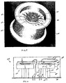
- FIG. 7 A cross-sectional illustration of an integrated aircraft wheel assembly 200 suitable for embodying the principles of the present invention is shown in Figure 7 and an isometric perspective of the wheel rim of the assembly 200 is shown in Figure 8 .
- a hubcap 202 is mounted to a wheel rim 204 of assembly 200.
- the hubcap 202 is cutaway to reveal the elements mounted thereto.
- the rim 204 is rotationally supported on an axle 206 which includes a central structure 208 extending out from the axle 206 to the hubcap 202.
- the diameter of the central structure 208 is substantially less than the diameter of the axle 206.
- annular shaped PC board layer 212 Mounted to an inside flat surface 210 of the hubcap 202 is an annular shaped PC board layer 212.
- the dual inductor wire loops 10 may be disposed on a surface of the layer 212. While only one layer 212 is shown in Figure 7 , it is understood that an embodiment of two similarly shaped layers sandwiched together with each layer having one of the dual loops 10 disposed thereon may work just as well.
- Another similar annular shaped PC board layer 214 may be mounted to the axle 206 and have disposed on a surface thereof the E-field receiving loop 32.
- the surfaces of the layers 212 and 214 on which the loops 10 and 32 are disposed should be mounted substantially paroles to each other and within a distance of no greater than twelve inches or approximately five centimeters apart, for example.
- the central structure 208 protrudes through the centers of the annular shaped layers 212 and 214 to the surface 210 of the hubcap 202.
- the magnetic interrogator 24 is disposed on the central structure 208 at a point near the surface 210 in close proximity to the dual loops 10 of layer(s) 212 so that its magnetic field is directed to induce a current in the dual loops 12 while not affecting substantially the E-field receiving loop 32.
- Wires 26 may extend from the landing gear strut mounted unit 54 through the center of axle 206 to the magnetic interrogator 24.
- wires 36 may extend from the receiving loop 32 of PC board layer 214 through the center of axle 206 to the strut mounted unit 54 as described herein above in connection with Figure 5 .
- dual, variable capacitance pressure sensors 16 are disposed in a common enclosure, like a TO-5 can, for example, of a sensor assembly 216.
- a hollow metal tube 218 is attached to the base of the TO-5 can of assembly 216 and is insertable into a cavity 220 of the wheel rim 204 at an insertion point 222.
- the cavity 220 extends from the insertion point 222 up through the rim 204 to the tire pressure chamber (not shown).
- a hole (not shown) is provided in the base of the TO-5 can at a point where the tube 218 is attached so that pressure from the tire chamber may be sensed by a pressure sensor in the assembly 216 via the path through cavity 220, tube 218 and the hole in the base of the assembly 216 as will become more evident from the description found herein below.
- a seal 223 may be included around the tube 218 at the insertion point 222 to ensure against air leakage from the cavity 220 to the atmosphere.
- Wiring from the dual pressure sensors of assembly 216 may be provided to their respective inductor loops in the hubcap 202 through a cable 224, which may be a coax cable, for example, and a connector 226, which may be a coax connector.
- the connector 226 is disposed through a wall of the hubcap 202 to permit the wiring thereof to pass through the wall and be connected to their respective loops on PC board layer(s) 212.
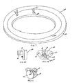
- FIG 9 is an illustration of an annular PC board layer 230 suitable for use as either the annular shaped layer(s) 212 or layer 214 in the embodiment of Figure 7 .
- a wire loop 232 which may be in the form of a copper tape, for example, is disposed on a surface 234 of the layer 230.
- Wire leads 236 of the wire loop 232 may extend out from the tape at an opening in the loop for providing connection points to the respective wiring through soldering, for example. If the layer 230 is embodying a single layer 212 then an additional loop may be disposed on a surface of the layer 230 with its own set of connecting leads.
- each set of connecting leads 236 are connected to the respective pressure sensor in assembly 216 via connector 226 and cable 224 (see Figure 7 ).
- layer 230 is embodying one of a dual layer structure, then two layers 230 may be sandwiched together to form the dual layer assembly. If the layer 230 is an embodiment of layer 214, then wire leads 236 are connected to the wires 36 via soldering, for example.
- wire circles 238 may be provided on surface 234 at a point 240 of loop 232 to increase the length and inductance of the loop 232 to provide an inductance range around the contemplated operational resonance frequency of the respective resonant circuit. Trimming the inductance to compensate for variations in the manufacturing process may be accomplished with the present embodiment by cutting or interrupting the connection of one or more of the wire circles from the wire loop 232, for example. In this manner, once trimmed, there is no further need to calibrate the resonant circuits, allowing the wheels to be changed with no adjustment in the exciter unit
- FIG 10 is a cross-sectional illustration of dual variable capacitance pressure sensors suitable for use in the sensor assembly 216 of the embodiment of Figure 7 .
- two variable capacitance pressure sensors 250 and 252 are disposed within a sealed TO-5 can 254.
- the sensors 250 and 252 are of the micro-electro-mechanical system or MEMS type fabricated from a silicon substrate and are substantially identical in structure.
- Each of the MEMS pressure sensors 250 and 252 may be of the type manufactured by Goodrich Sensor Systems under the model or part no. 02011-0910-0750, for example.
- Each MEMS pressure sensor 250 and 252 includes a silicon substrate 256 which is supported from the base 258 of the can 254 by a cylindrical hollow pedestal 260 and acts as one plate of a capacitive element
- a hole 262 is provided in the base 258 aligned with the hollow portion 264 of the pedestal 260 of one of the MEMS sensors 252.
- the hollow pedestal of the other sensor 250 is sealed by the base 258.
- the other plate of the capacitive element is formed in each MEMS sensor by fabricating a silicon diaphragm 266 over and electrically isolated from the substrate layer 256 creating a chamber 268 between the plate of the diaphragm 266 and the plate of the substrate 256.
- a pathway 270 is provided in the substrate 256 between the hollow portion 264 and chamber 268.
- the hollow tube 218 is affixed to the base 258 concentrically aligned with the hole 262.
- a vacuum is created in the sealed volume under the cover 302 by drawing air through a tube 304 in the cover 302. Once the vacuum is created, the tube 304 is sealed to maintain the vacuum.
- a seal (not shown), which may be an O-ring, for example, is disposed around the periphery of the tube 218 at section 306 prior to the tube 218 being inserted in the cavity 220. Once the tube 218 is positioned in place, the assembly 216 may be secured to the wheel rim 204 by screws through screw holes 308 and 310, for example.
- air pressure from the tire chamber is sensed in chamber 268 of sensor 252 via the path formed by cavity 220, tube 218, hole 262, hollow pedestal portion 264, and substrate pathway 270.
- Pressure in chamber 268 causes the capacitive plate of diaphragm 266 to move with respect to the capacitive plate of stationary substrate 256, thus varying the capacitance in proportion to the sensed pressure.
- the capacitance of sensor 252 will also vary with changing temperature and other parameters. Since sensor 250 is not sensing tire pressure, the capacitance thereof will only vary with the changing temperature and other parameters which are substantially the same for both sensors.
- the inductor loops of the dual resonant circuits are fixed and temperature stabilized for the most part.
- the resonant frequency of the reference LC circuit may be used to compensate the resonant frequency of the pressure measuring LC circuit by taking the differential resonant frequency between the two as described herein above in connection with Figure 1A .
- wheel speed may be also sensed wirelessly by the foregoing described embodiment(s) with a minor modification and/or addition of one or more components.
- the basic concept of wireless wheel speed sensing utilizing the present tire pressure sensing embodiment(s) is to cause a rate of amplitude modulations of the variable frequency magnetic field between the rotational and static loop circuits commensurate with the wheel speed.
- One technique for creating the rate of amplitude modulations is to provide breaks or interruptions, i.e. inductive discontinuities, in the magnetic coupling between the interrogator 24 and resonant loop 10.
- the illustration of Figure 12 depicts the addition of a shuttering mechanism 320 to the embodiment of Figures 7 and 8 for this purpose.
- the shuttering mechanism 320 comprises a plurality of magnetic shield gratings 322 that are disposed on the insulating layer 212 about the perimeter of wire loop 10 at predetermined spacing intervals.
- the gratings 322 are constructed of a high conductivity material such as Aluminum, for example, for RF magnetic shielding. Generally, RF magnetic shielding balances EMI type shielding vs high permeability materials.
- the gratings 322 may be disposed on both sides of the layer 212 in which the loop 10 is embedded.
- each of the gratings 322 is attached at one end by fasteners 324 to a surface of the layer 212, cantilevered over top of the loop 10, and isolated therefrom.
- the fasteners 324 which may be screws, for example, extend through the layer 212 to a grounded surface such as the wheel hub, for example, to provide an electrical grounding for each of the gratings 322 so they do not become a re-radiator of the magnetic field themselves.
- the inductive loop 10 is electrically insulated from the electrical ground and structurally supported within layer 212 which may be constructed of a plastic material for the present embodiment.
- a circular ring 326 may couple together the unattached ends of the gratings 322.
- the center hole of the ring 326 is aligned substantially with the center hole of the layer 212.
- the outer diameter of the circular ring 326 is less than the diameter of the inductive loop 10, but the gratings 322 extend over the loop 10 to act as barriers or shields to the magnetic field between the magnetic interrogator 24 and the loop 10.
- the ring 326 is also electrically grounded through its contact with the grounded gratings 322.
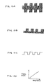
- variable frequency E-field signal received over signal lines 36 will have a rate of amplitude modulations commensurate with wheel rotational speed as illustrated in the exemplary waveform of Figure 13A .
- the signal over lines 36 may be sensed by the wide frequency bandwidth operational amplifier as described above in connection with the embodiment of Figure 6 and provided to a wheel speed detector circuit 340 which is added to the tire pressure sensing system embodiment described in connection with Figure 3 .
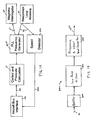
- the modified embodiment is shown in the block diagram schematic of Figure 14 .
- the wheel speed detector circuit 340 determines wheel speed from the sensed, amplitude modulated E-field signal shown by way of example in Figure 13A .
- a signal representative of wheel speed is provided to the aircraft bus via bus interface 46 over signal lines 342.
- FIG 15 is a block diagram schematic of an exemplary wheel speed detector circuit 340 suitable for use in the embodiment of Figure 14 .
- the sensed E-field signal is received and rectified by a rectifier circuit 344 which may perform either a full wave or half-wave rectification.
- the resultant waveform which is shown by way of example in Figure 13B is passed to a low-pass filter circuit 346 which filters out the higher frequency components of the waveform.
- the filtered waveform results in amplitude modulated pulses as shown by way of example in Figure 13C .
- the frequency of the pulses are commensurate with the wheel speed.
- a circuit 348 determines the frequency of the pulses of the rectified and filtered signal by way of a frequency counter, for example, and converts the determined frequency to a signal representative of wheel speed according to a predetermined function which is exemplified in the graph of Figure 13D .
- the wheel speed signal is output from the circuit 348 over signal lines 342 to the bus interface 46. In this manner, wheel speed may be wirelessly sensed by the modified tire pressure system embodiment of Figures 12 , 14 and 15 .
- a second set of gratings aligned concentric to the first may be added to the embodiment of Figure 12 .
- the second set of gratings may be static in relation to the first set of gratings 322 which rotates as described above.
- the second set of gratings may be attached to a surface of the layer 214 as shown in Figure 12 over the receiving loop 32 in a similar manner as described for the first set of gratings 322, for example, except that the second set of gratings are structurally and electrically attached to the axle 214 or associated static parts using fasteners or welding techniques.
- the axle 214 or associated static parts are grounded.
- the E-field loop 32 would be electrically insulated from electrical ground and structurally supported within layer 214 which is constructed of a plastic material for the present embodiment. As the wheel rotates, openings between the gratings of two sets of gratings are created at a rate commensurate with wheel speed. This embodiment will create a larger change in amplitude in the received signal, since it creates effectively a complete shield at regular points during the rotation of the wheel.
- While the present embodiment employs a rotating plurality of gratings 322 or a rotating and static set of gratings as described above to achieve the desired amplitude modulations, it is understood that other embodiments or even other shuttering mechanisms may be employed without deviating from the broad principles of the present aspect of the invention.
- Such other shuttering mechanisms may take the form of holes or apertures in a disc attached above the loop 10 or a combination of fixed and a static holed discs as described above. Wired spokes that act as RF magnetic shields may be used instead of gratings to provide the desired modulations in the RF throughput.
- Another possible technique to sensitize the magnetic field to wheel rotation is to alter the shapes of the transponder and receiver loops.
- the distance between the two loops 10 and 32 varies as the wheel rotates.
- the science of Physics dictates that the transmitting of electromagnetic radiation will vary with the inverse of the square of the distance between the loops 10 and 32. Therefore, as this distance varies with rotation, the E-field signal will be amplitude modulated commensurate with wheel speed.
- the inductive wire loop 10 may be shaped on the surface of layer 212 in the form of a multiple pointed star with regular distance intervals 350 around the wire perimeter between star apexes 352.
- the E-field loop 32 may be shaped on the surface of layer 214 in the same or similar form as that of the wire loop 10.
- the star apexes 352 thereof will align at regular intervals in time and create amplitude modulations in the signal 36 at a rate commensurate with wheel speed.
- the received signal 36 may be processed by the wheel speed detector circuit 340 in the same or similar manner as described herein above.
- wire loops into multiple pointed stars to achieve the desired amplitude modulations
- other shapes of the wire loops are possible without deviating from the broad principles of the present aspect of the invention.
- Such other shapes may take the form of square waves or sine waves or any shape that varies radially or axially in a regular pattern, for example.
- Another possible technique to effect the desired amplitude modulation for wireless wheel speed sensing is to locate ferro-magnetic material relative to the magnetic interrogator 24 and transponder loop 10 in order to enhance or detract the magnetic coupling therebetween.
- the use of ferrite material embedded in the insulated layer 212 at regular intervals and in close proximity to the transmitting loop 10 will create a distortion of the RF magnetic waves, resulting in a deviation in the characteristic of the magnetic flux lines intersecting the transmitting loop 10 and, in turn, a fluctuation in the E-field signal as the wheel rotates.
- This technique may be also used in the same or similar manner as described herein above for the grating embodiment of Figure 12 with ferrite material embedded near both loops 10 and 32, for example.
Landscapes
- Physics & Mathematics (AREA)
- General Physics & Mathematics (AREA)
- Engineering & Computer Science (AREA)
- Mechanical Engineering (AREA)
- Measuring Fluid Pressure (AREA)
- Arrangements For Transmission Of Measured Signals (AREA)
Claims (7)
- Système sans fil de détection de pression de pneu et de vitesse de roue pour un aéronef, ledit système comprenant :un circuit de résonance (10) monté sur une roue (52) de l'aéronef pour contrôler la pression d'un pneu monté sur ladite roue, ledit circuit de résonance comportant une boucle de fil métallique (12) d'une inductance prédéterminée;un circuit d'interrogation (14) pouvant être couplé magnétiquement audit circuit de résonance (10) et opérationnel pour induire magnétiquement un courant de fréquence variable dans la boucle de fil métallique (12) dudit circuit de résonance (10), ledit circuit de résonance (10) générant un champ électrique de fréquence variable correspondant en réponse audit courant induit, ledit champ électrique de fréquence variable incluant une fréquence de résonance proportionnée à la pression dudit pneu ;un circuit de réception (34) de champ électrique pouvant être couplé audit circuit de résonance (10) et opérationnel pour recevoir ledit champ électrique de fréquence variable modulé en amplitude dudit circuit de résonance (10) et pour générer un signal représentatif de celui-ci ; etun premier circuit de traitement (20) couplé audit circuit de réception pour traiter ledit signal pour générer une lecture de pression dudit pneu en se basant sur la fréquence de résonance de celui-ci ;caractérisé en ce que :le système comprend en outre un appareil de modification de champ magnétique permettant de modifier le couplage magnétique entre ladite boucle de fil métallique et ledit circuit d'interrogation pour rendre une vitesse de modulations d'amplitude dudit champ électrique de fréquence variable proportionnée à ladite vitesse de roue ; etun second circuit de traitement (348) couplé audit circuit de réception pour traiter ledit signal en vue de générer une lecture de vitesse de roue basée sur la vitesse des modulations d'amplitude de celui-ci.
- Système selon la revendication 1, dans lequel l'appareil de modification de champ magnétique comprend une pluralité de réseaux de champ magnétique (322) disposés sur la roue autour du périmètre de la boucle de fil métallique à des intervalles prédéterminés pour une rotation avec celle-ci, lesdits réseaux (322) agissant comme des obturateurs du couplage magnétique aux intervalles prédéterminés pendant une rotation de la roue.
- Système selon la revendication 2, dans lequel les réseaux (322) sont électriquement mis à la masse pour en empêcher le rayonnement d'un champ magnétique.
- Système selon la revendication 1, dans lequel l'appareil de modification de champ magnétique comprend des première et seconde pluralités disposées concentriquement de réseaux de champ magnétique (322), ladite première pluralité de réseaux disposés sur la roue (52) autour du périmètre de ladite boucle de fil métallique (12) à des intervalles prédéterminés pour une rotation avec celle-ci, et ladite seconde pluralité de réseaux étant montée stationnaire par rapport à ladite première pluralité de réseaux (322), lesdites première et seconde pluralités de réseaux agissant comme des obturateurs du couplage magnétique aux intervalles prédéterminés pendant une rotation de la roue.
- Système selon la revendication 1, dans lequel l'appareil de modification de champ magnétique comprend une pluralité d'éléments en matériau ferromagnétique disposés sur la roue (52) autour du périmètre de ladite boucle de fil métallique (12) à des intervalles prédéterminés pour une rotation avec celle-ci.
- Système selon la revendication 1, dans lequel l'appareil de modification de champ magnétique comprend une pluralité d'aimants permanents disposés sur la roue autour du périmètre de ladite boucle de fil métallique (12) à des intervalles prédéterminés pour une rotation avec celle-ci.
- Système selon la revendication 1, incluant une plate-forme d'aéronef, et dans lequel les premier et second circuits de traitement (20, 348) sont couplés à ladite plate-forme d'aéronef pour réaliser la lecture de pression de pneu et la lecture de vitesse de roue sur la plate-forme d'aéronef.
Applications Claiming Priority (2)
| Application Number | Priority Date | Filing Date | Title |
|---|---|---|---|
| US10/647,487 US7202778B2 (en) | 2003-08-25 | 2003-08-25 | Wireless tire pressure sensing system |
| EP04816823A EP1663675B1 (fr) | 2003-08-25 | 2004-08-24 | Systeme sans fil de detection de pression des pneus et/ou de vitesse des roues pour aeronef |
Related Parent Applications (1)
| Application Number | Title | Priority Date | Filing Date |
|---|---|---|---|
| EP04816823.1 Division | 2004-08-24 |
Publications (2)
| Publication Number | Publication Date |
|---|---|
| EP2236320A1 EP2236320A1 (fr) | 2010-10-06 |
| EP2236320B1 true EP2236320B1 (fr) | 2011-11-23 |
Family
ID=34216514
Family Applications (2)
| Application Number | Title | Priority Date | Filing Date |
|---|---|---|---|
| EP04816823A Expired - Lifetime EP1663675B1 (fr) | 2003-08-25 | 2004-08-24 | Systeme sans fil de detection de pression des pneus et/ou de vitesse des roues pour aeronef |
| EP10006328A Expired - Lifetime EP2236320B1 (fr) | 2003-08-25 | 2004-08-24 | Système de détection de vitesse des roues et de la pression des pneus sans fil pour avion |
Family Applications Before (1)
| Application Number | Title | Priority Date | Filing Date |
|---|---|---|---|
| EP04816823A Expired - Lifetime EP1663675B1 (fr) | 2003-08-25 | 2004-08-24 | Systeme sans fil de detection de pression des pneus et/ou de vitesse des roues pour aeronef |
Country Status (3)
| Country | Link |
|---|---|
| US (2) | US7202778B2 (fr) |
| EP (2) | EP1663675B1 (fr) |
| WO (1) | WO2005043264A2 (fr) |
Families Citing this family (48)
| Publication number | Priority date | Publication date | Assignee | Title |
|---|---|---|---|---|
| US8032659B2 (en) * | 2003-01-21 | 2011-10-04 | Nextio Inc. | Method and apparatus for a shared I/O network interface controller |
| US7202778B2 (en) * | 2003-08-25 | 2007-04-10 | Rosemount Aerospace Inc. | Wireless tire pressure sensing system |
| US7245117B1 (en) | 2004-11-01 | 2007-07-17 | Cardiomems, Inc. | Communicating with implanted wireless sensor |
| US8026729B2 (en) | 2003-09-16 | 2011-09-27 | Cardiomems, Inc. | System and apparatus for in-vivo assessment of relative position of an implant |
| AU2004274005A1 (en) * | 2003-09-16 | 2005-03-31 | Cardiomems, Inc. | Implantable wireless sensor |
| US20060287602A1 (en) * | 2005-06-21 | 2006-12-21 | Cardiomems, Inc. | Implantable wireless sensor for in vivo pressure measurement |
| US20070182530A1 (en) * | 2004-03-01 | 2007-08-09 | Ekkehard Pilz | Power and data transmission device |
| JP2006142856A (ja) * | 2004-11-16 | 2006-06-08 | Alps Electric Co Ltd | タイヤ情報検出装置 |
| AU2006220733B2 (en) * | 2005-03-04 | 2011-01-27 | Cardiomems, Inc. | Communicating with an implanted wireless sensor |
| TWI266486B (en) * | 2005-06-08 | 2006-11-11 | Via Tech Inc | Cyclic pipeline analog to digital converter |
| CA2613241A1 (fr) | 2005-06-21 | 2007-01-04 | Cardiomems, Inc. | Procede de fabrication de capteur sans fil implantable pour la mesure de pression in vivo |
| JP2007096363A (ja) * | 2005-08-31 | 2007-04-12 | Tdk Corp | モノポールアンテナ |
| ES2321757T3 (es) | 2005-11-29 | 2009-06-10 | Messier-Bugatti | Equipo del extremo de un eje de un vehiculo, especialmente una aeronave. |
| FR2894055B1 (fr) * | 2005-11-29 | 2008-02-08 | Messier Bugatti Sa | Equipement d'extremite d'essieu de vehicule, notamment aeronef. |
| FR2899870B1 (fr) * | 2006-04-13 | 2008-07-04 | Messier Bugatti Sa | Equipement d'extremite d'essieu de vehicule, notamment d'aeronef |
| US7377168B2 (en) * | 2005-12-13 | 2008-05-27 | Honeywell International Inc. | Wireless sensor antenna configuration |
| JP4856423B2 (ja) * | 2005-12-27 | 2012-01-18 | 太平洋工業株式会社 | タイヤ情報通信システム |
| US20080018424A1 (en) * | 2006-07-10 | 2008-01-24 | 3M Innovative Properties Company | Inductive sensor |
| US7948380B2 (en) * | 2006-09-06 | 2011-05-24 | 3M Innovative Properties Company | Spatially distributed remote sensor |
| NL1033148C2 (nl) * | 2006-12-29 | 2008-07-01 | Univ Delft Tech | Elektrische meetinrichting, werkwijze en computer programma product. |
| DE102007030356A1 (de) * | 2007-06-29 | 2009-01-02 | Tech21 Gmbh | Registriereinheit zur Erfassung von durch mechanische Einwirkungen auf diese hervorgerufenen Eingabesignalen und Verfahren zur Meßwerterfassung und Signalverarbeitung |
| FR2918606B1 (fr) * | 2007-07-11 | 2009-10-09 | Michelin Soc Tech | Dispositif de surveillance d'un parametre physique d'etat d'un pneu, utilisant un capteur librement mobile |
| US20090192667A1 (en) * | 2007-08-01 | 2009-07-30 | Eldec Corporation | Tire monitoring system |
| US8519869B2 (en) | 2008-03-21 | 2013-08-27 | Eldec Corporation | Aircraft tire pressure loop link |
| CA2719294C (fr) * | 2008-03-21 | 2016-08-23 | Eldec Corporation | Liaison en boucle de pression de pneu d'avion |
| US9614377B2 (en) * | 2008-03-21 | 2017-04-04 | Eldec Corporation | Aircraft tire pressure sensor resonant loop link |
| US8215162B2 (en) * | 2009-07-27 | 2012-07-10 | Eldec Corporation | Focused field antenna for passive RFID tire pressure sensor transponder |
| ITTO20091060A1 (it) | 2009-12-30 | 2011-06-30 | Telecom Italia Spa | Sistema e metodo di trasferimento di energia senza fili per l alimentazione di un carico elettrico |
| WO2013149187A1 (fr) * | 2012-03-30 | 2013-10-03 | Eldec Corporation | Liaison en boucle de pression de pneu d'avion |
| US9354635B2 (en) | 2012-06-05 | 2016-05-31 | Textron Innovations Inc. | Takeoff/landing touchdown protection management system |
| US9381779B2 (en) * | 2012-07-09 | 2016-07-05 | Meggitt (Orange County), Inc. | System and method for thermal mitigation for tire pressure measurement electronics |
| US9794346B2 (en) | 2012-12-11 | 2017-10-17 | The Boeing Company | Monitoring systems of a vehicle by generating and transmitting customized information messages to wireless networked computers |
| TW201442891A (zh) * | 2013-05-06 | 2014-11-16 | Cub Elecparts Inc | 磁力傳輸式胎壓感測器及設定工具與設定方法 |
| US20150284108A1 (en) * | 2014-04-07 | 2015-10-08 | Goodrich Corporation | Nose wheel tire pressure sensing system and apparatus |
| US9707807B2 (en) * | 2014-06-27 | 2017-07-18 | Goodrich Corporation | Pinless inductive connector assembly |
| CA2959156C (fr) * | 2014-08-26 | 2023-02-21 | Eldec Corporation | Liaison de boucles resonantes de capteur de pression de pneu d'aeronef |
| US10308352B2 (en) * | 2014-12-12 | 2019-06-04 | Borealis Technical Limited | Monitoring system for aircraft drive wheel system |
| US9757995B2 (en) * | 2015-03-26 | 2017-09-12 | Goodrich Corporation | Hub cap data repeater circuit |
| US9457627B1 (en) * | 2015-04-15 | 2016-10-04 | Goodrich Corporation | Handheld interrogation and display for remote sensors |
| GB2550174A (en) * | 2016-05-11 | 2017-11-15 | Airbus Operations Ltd | Tyre deflection monitoring |
| AU2017203411A1 (en) * | 2016-06-01 | 2017-12-21 | Strata Products Worldwide, Llc | Method and apparatus for identifying when an idividual is in proximity to an object |
| KR102601737B1 (ko) * | 2018-05-03 | 2023-11-10 | 엘지전자 주식회사 | 무선 전력 수신 장치 및 무선 전력 전송 시스템 |
| GB2575974A (en) * | 2018-07-27 | 2020-02-05 | Airbus Operations Ltd | Aircraft landing |
| CN110588257B (zh) * | 2019-09-23 | 2024-05-10 | 西安航空制动科技有限公司 | 一种分离式胎压传感器 |
| CN112706566B (zh) * | 2021-01-08 | 2022-01-04 | 南京航空航天大学 | 一种基于乐甫波传感器的飞机胎压监测系统及监测方法 |
| CN115447324B (zh) * | 2022-11-03 | 2023-01-17 | 石家庄铁道大学 | 一种轮胎温度检测系统及方法 |
| CN117104528B (zh) * | 2023-10-19 | 2024-01-23 | 四川腾盾科技有限公司 | 一种前三点式无人机起飞离地定位装置及其试飞计算方法 |
| US20250306159A1 (en) * | 2024-04-01 | 2025-10-02 | The Boeing Company | Systems and methods for automatic direction finding |
Family Cites Families (36)
| Publication number | Priority date | Publication date | Assignee | Title |
|---|---|---|---|---|
| US2274557A (en) * | 1940-07-10 | 1942-02-24 | Morgan Raymond | Electric gauge |
| US3662335A (en) * | 1969-10-08 | 1972-05-09 | Kurt Fritze | Device for road vehicles for the wireless transmission of at least one measured value of a rotating wheel to an indicating instrument |
| US3723966A (en) * | 1970-09-14 | 1973-03-27 | Bendix Corp | Interrogating tire pressure indicator |
| FR2212245B1 (fr) * | 1972-12-30 | 1976-11-19 | Toyo Tire & Rubber Co | |
| US3911434A (en) * | 1973-02-12 | 1975-10-07 | Tele Sensors Inc | Data transmission system employing a harmonic transponder including means for varying phase in response to surrounding conditions |
| JPS5548355B2 (fr) * | 1973-11-28 | 1980-12-05 | ||
| JPS5115949U (fr) * | 1974-07-12 | 1976-02-05 | ||
| US4074227A (en) * | 1974-11-15 | 1978-02-14 | Kalmus Henry P | Tire pressure indicator |
| DE2951139A1 (de) | 1979-12-19 | 1981-07-02 | Robert Bosch Gmbh, 7000 Stuttgart | Einrichtung zur kontinuierlichen ueberwachung des luftdruckes in fahrzeugreifen |
| US4409586A (en) * | 1981-05-26 | 1983-10-11 | Hochstein Peter A | Tire condition monitor converter |
| US4389884A (en) * | 1981-06-15 | 1983-06-28 | Gianluigi Agulia | Remote tire pressure indicator |
| US4588978A (en) * | 1984-06-21 | 1986-05-13 | Transensory Devices, Inc. | Remote switch-sensing system |
| US4717905A (en) * | 1985-05-24 | 1988-01-05 | Roger W. Vernon | Warning system including means for remotely energizing condition sensing device |
| US4953393A (en) * | 1986-07-04 | 1990-09-04 | Philip Elliot Galasko | Transducer |
| JPS63306905A (ja) | 1987-06-10 | 1988-12-14 | Sumitomo Electric Ind Ltd | タイヤ空気圧検出装置 |
| EP0450653B1 (fr) * | 1990-04-05 | 1994-06-15 | Nippondenso Co., Ltd. | Appareil de détection de pression de pneumatiques pour véhicule |
| US5274355A (en) * | 1992-02-05 | 1993-12-28 | Louis Galan | System for monitoring pressure and temperature of pneumatic tires on a moving vehicle |
| US5542118A (en) * | 1992-02-18 | 1996-07-30 | Warnagiris; Thomas J. | Induction field coupled transmission system incorporating a passive transmitter |
| US6748797B2 (en) * | 2000-09-08 | 2004-06-15 | Automotive Technologies International Inc. | Method and apparatus for monitoring tires |
| US5227798A (en) * | 1992-06-24 | 1993-07-13 | The United States Of America As Represented By The Secretary Of The Air Force | Passive transmitting sensor |
| US5515041A (en) * | 1993-06-14 | 1996-05-07 | Simmonds Precision Products Inc. | Composite shaft monitoring system |
| JP3494440B2 (ja) * | 1996-05-29 | 2004-02-09 | バーテルズ・マンゴルト・エレクトロニック・ゲーエムベーハー | 可動部から無線電送するための装置 |
| DE19649277A1 (de) * | 1996-11-28 | 1998-06-04 | Bosch Gmbh Robert | Fahrzeuginterne Vorrichtung zur Luftdrucküberwachung eines Reifens eines Fahrzeugs |
| US6124787A (en) | 1997-01-15 | 2000-09-26 | Algonquin Scientific, Llc | Tire pressure sensing system |
| US6362732B1 (en) * | 1997-01-15 | 2002-03-26 | Algonquin Scientific Llc | Tire pressure sensing system |
| GR1003470B (el) * | 1998-10-15 | 2000-11-03 | Συσκευη για την ενδειξη υπερβασης του ανωτερου και κατωτερου οριου ασφαλειας πιεσης αερα στους ελαστικους τροχους ενος οχηματος | |
| DE19853135B4 (de) | 1998-11-18 | 2011-02-03 | Robert Bosch Gmbh | Vorrichtung und Verfahren zur drahtlosen Druckmessung |
| EP1150849B1 (fr) * | 1999-02-11 | 2003-05-07 | Emtop Limited | Appareil et procede de transmission de signaux, appareil de mesurage et appareil de detection de la pression des pneus incorporant un tel appareil de transmission des signaux |
| FR2794065B1 (fr) * | 1999-05-28 | 2001-06-22 | Sagem | Systeme securise de controle de la pression d'un pneumatique |
| US6591671B2 (en) * | 1999-08-16 | 2003-07-15 | The Goodyear Tire & Rubber Company | Monitoring pneumatic tire conditions |
| DE50114839D1 (de) * | 2000-08-02 | 2009-05-28 | Continental Teves Ag & Co Ohg | Aktiver magnetfeldsensor, dessen verwendung, verfahren und vorrichtung |
| US20020092347A1 (en) * | 2001-01-17 | 2002-07-18 | Niekerk Jan Van | Radio frequency identification tag tire inflation pressure monitoring and location determining method and apparatus |
| US6741169B2 (en) * | 2001-07-06 | 2004-05-25 | Trw Inc. | Tire tread integrity monitoring system and method |
| US6759952B2 (en) * | 2001-07-06 | 2004-07-06 | Trw Inc. | Tire and suspension warning and monitoring system |
| FR2831669B1 (fr) * | 2001-10-31 | 2004-04-02 | Johnson Contr Automotive Elect | Procede et systeme de mesure de la vitesse de rotation des roues d'un vehicule automobile |
| US7202778B2 (en) * | 2003-08-25 | 2007-04-10 | Rosemount Aerospace Inc. | Wireless tire pressure sensing system |
-
2003
- 2003-08-25 US US10/647,487 patent/US7202778B2/en not_active Expired - Fee Related
-
2004
- 2004-08-24 EP EP04816823A patent/EP1663675B1/fr not_active Expired - Lifetime
- 2004-08-24 WO PCT/US2004/027443 patent/WO2005043264A2/fr not_active Ceased
- 2004-08-24 EP EP10006328A patent/EP2236320B1/fr not_active Expired - Lifetime
-
2005
- 2005-07-27 US US11/190,404 patent/US7397353B2/en not_active Expired - Fee Related
Also Published As
| Publication number | Publication date |
|---|---|
| US20050264406A1 (en) | 2005-12-01 |
| WO2005043264A3 (fr) | 2006-03-02 |
| US7202778B2 (en) | 2007-04-10 |
| EP2236320A1 (fr) | 2010-10-06 |
| WO2005043264A2 (fr) | 2005-05-12 |
| US20050046558A1 (en) | 2005-03-03 |
| EP1663675B1 (fr) | 2011-07-27 |
| EP1663675A2 (fr) | 2006-06-07 |
| US7397353B2 (en) | 2008-07-08 |
Similar Documents
| Publication | Publication Date | Title |
|---|---|---|
| EP2236320B1 (fr) | Système de détection de vitesse des roues et de la pression des pneus sans fil pour avion | |
| US4749993A (en) | Arrangement for the wireless transmission of measuring signals | |
| US4334428A (en) | Apparatus for indicating parameters sensed on a rotatable wheel | |
| JP2003094917A (ja) | 空気タイヤモニターシステムおよび空気タイヤモニター | |
| JP3472578B2 (ja) | 角度位置エンコーダ | |
| US6885111B2 (en) | Method for generating an electric current within a tire | |
| CA1072639A (fr) | Methode et manometre electronique pour mesurer la pression d'air dans les pneus | |
| EP0202375A1 (fr) | Dispositif d'indication de pression de pneu | |
| AU2003285990B2 (en) | Improvements in tyre data monitoring systems | |
| GB2337335A (en) | Tire pressure sensing system | |
| JP2002324292A (ja) | 空気入りタイヤの状態の監視 | |
| US20070222569A1 (en) | Tire, wheel or tire an wheel assembly equipped with a device for counting the number of rotations | |
| KR100286191B1 (ko) | 힘 및 모멘트 감지용 측정 휠 | |
| JPS5947696A (ja) | 因子測定装置 | |
| US6889543B2 (en) | Wheel assembly provided with a pressure sensor | |
| US20080246467A1 (en) | Device For Counting the Rotations of an Object in a Referential, and Method For Controlling One Such Device | |
| CN112384383A (zh) | 包括双模天线电路的用于车轮的无线电发射传感器 | |
| JPS63306905A (ja) | タイヤ空気圧検出装置 | |
| US20070279204A1 (en) | Method and system for tire inflation monitoring | |
| US20220404386A1 (en) | Health-monitoring system for a device determining rotation frequency of a shaft | |
| WO1993004349A1 (fr) | Capteur de pression magnetostrictif | |
| JP4252768B2 (ja) | 非接触物理量測定方法および物理量測定装置および半導体素子。 | |
| US11203416B2 (en) | Systems and methods for variable gap wireless power and communication | |
| JPS61278731A (ja) | タイヤ圧力測定装置 | |
| JPS61141098A (ja) | タイヤ・リム組立体の状態変化検知装置 |
Legal Events
| Date | Code | Title | Description |
|---|---|---|---|
| PUAI | Public reference made under article 153(3) epc to a published international application that has entered the european phase |
Free format text: ORIGINAL CODE: 0009012 |
|
| AC | Divisional application: reference to earlier application |
Ref document number: 1663675 Country of ref document: EP Kind code of ref document: P |
|
| AK | Designated contracting states |
Kind code of ref document: A1 Designated state(s): DE FR GB |
|
| 17P | Request for examination filed |
Effective date: 20110322 |
|
| RIC1 | Information provided on ipc code assigned before grant |
Ipc: B60C 23/04 20060101AFI20110414BHEP |
|
| GRAP | Despatch of communication of intention to grant a patent |
Free format text: ORIGINAL CODE: EPIDOSNIGR1 |
|
| RTI1 | Title (correction) |
Free format text: A WIRELESS TIRE PRESSURE AND WHEEL SPEED SENSING SYSTEM FOR AIRCRAFT |
|
| RIN1 | Information on inventor provided before grant (corrected) |
Inventor name: NORLIEN, JOHN A. Inventor name: KUNIK, WILLIAM G. Inventor name: BUENZ, MARK J. Inventor name: MYHRE, DOUGLAS C. Inventor name: WILLIAMS, WADE W. |
|
| GRAS | Grant fee paid |
Free format text: ORIGINAL CODE: EPIDOSNIGR3 |
|
| GRAA | (expected) grant |
Free format text: ORIGINAL CODE: 0009210 |
|
| AC | Divisional application: reference to earlier application |
Ref document number: 1663675 Country of ref document: EP Kind code of ref document: P |
|
| AK | Designated contracting states |
Kind code of ref document: B1 Designated state(s): DE FR GB |
|
| REG | Reference to a national code |
Ref country code: GB Ref legal event code: FG4D |
|
| REG | Reference to a national code |
Ref country code: DE Ref legal event code: R096 Ref document number: 602004035464 Country of ref document: DE Effective date: 20120308 |
|
| PLBE | No opposition filed within time limit |
Free format text: ORIGINAL CODE: 0009261 |
|
| STAA | Information on the status of an ep patent application or granted ep patent |
Free format text: STATUS: NO OPPOSITION FILED WITHIN TIME LIMIT |
|
| 26N | No opposition filed |
Effective date: 20120824 |
|
| REG | Reference to a national code |
Ref country code: DE Ref legal event code: R097 Ref document number: 602004035464 Country of ref document: DE Effective date: 20120824 |
|
| REG | Reference to a national code |
Ref country code: FR Ref legal event code: PLFP Year of fee payment: 12 |
|
| PGFP | Annual fee paid to national office [announced via postgrant information from national office to epo] |
Ref country code: GB Payment date: 20150724 Year of fee payment: 12 Ref country code: DE Payment date: 20150722 Year of fee payment: 12 |
|
| PGFP | Annual fee paid to national office [announced via postgrant information from national office to epo] |
Ref country code: FR Payment date: 20150727 Year of fee payment: 12 |
|
| REG | Reference to a national code |
Ref country code: DE Ref legal event code: R119 Ref document number: 602004035464 Country of ref document: DE |
|
| GBPC | Gb: european patent ceased through non-payment of renewal fee |
Effective date: 20160824 |
|
| REG | Reference to a national code |
Ref country code: FR Ref legal event code: ST Effective date: 20170428 |
|
| PG25 | Lapsed in a contracting state [announced via postgrant information from national office to epo] |
Ref country code: DE Free format text: LAPSE BECAUSE OF NON-PAYMENT OF DUE FEES Effective date: 20170301 Ref country code: FR Free format text: LAPSE BECAUSE OF NON-PAYMENT OF DUE FEES Effective date: 20160831 Ref country code: GB Free format text: LAPSE BECAUSE OF NON-PAYMENT OF DUE FEES Effective date: 20160824 |