EP2236409A2 - Elektrisches Schiffsantriebssystem - Google Patents
Elektrisches Schiffsantriebssystem Download PDFInfo
- Publication number
- EP2236409A2 EP2236409A2 EP10158673A EP10158673A EP2236409A2 EP 2236409 A2 EP2236409 A2 EP 2236409A2 EP 10158673 A EP10158673 A EP 10158673A EP 10158673 A EP10158673 A EP 10158673A EP 2236409 A2 EP2236409 A2 EP 2236409A2
- Authority
- EP
- European Patent Office
- Prior art keywords
- electric propulsion
- engine
- induction motor
- propulsion system
- ship
- Prior art date
- Legal status (The legal status is an assumption and is not a legal conclusion. Google has not performed a legal analysis and makes no representation as to the accuracy of the status listed.)
- Withdrawn
Links
- 230000001360 synchronised effect Effects 0.000 claims abstract description 75
- 230000006698 induction Effects 0.000 claims abstract description 51
- 230000005611 electricity Effects 0.000 claims abstract description 23
- 238000006243 chemical reaction Methods 0.000 claims description 13
- 238000010586 diagram Methods 0.000 description 12
- 238000002485 combustion reaction Methods 0.000 description 6
- 230000002441 reversible effect Effects 0.000 description 5
- 230000008859 change Effects 0.000 description 3
- 230000007547 defect Effects 0.000 description 3
- 239000000446 fuel Substances 0.000 description 3
- 238000004519 manufacturing process Methods 0.000 description 3
- 230000007935 neutral effect Effects 0.000 description 3
- 230000009467 reduction Effects 0.000 description 3
- 230000001133 acceleration Effects 0.000 description 2
- 238000004880 explosion Methods 0.000 description 2
- 230000007246 mechanism Effects 0.000 description 2
- 230000004048 modification Effects 0.000 description 2
- 238000012986 modification Methods 0.000 description 2
- 239000002699 waste material Substances 0.000 description 2
- 230000005540 biological transmission Effects 0.000 description 1
- 230000006835 compression Effects 0.000 description 1
- 238000007906 compression Methods 0.000 description 1
- 230000008878 coupling Effects 0.000 description 1
- 238000010168 coupling process Methods 0.000 description 1
- 238000005859 coupling reaction Methods 0.000 description 1
- 230000007423 decrease Effects 0.000 description 1
- 230000002427 irreversible effect Effects 0.000 description 1
- 238000000034 method Methods 0.000 description 1
- 238000007789 sealing Methods 0.000 description 1
Images

Classifications
-
- B—PERFORMING OPERATIONS; TRANSPORTING
- B63—SHIPS OR OTHER WATERBORNE VESSELS; RELATED EQUIPMENT
- B63H—MARINE PROPULSION OR STEERING
- B63H23/00—Transmitting power from propulsion power plant to propulsive elements
- B63H23/22—Transmitting power from propulsion power plant to propulsive elements with non-mechanical gearing
- B63H23/24—Transmitting power from propulsion power plant to propulsive elements with non-mechanical gearing electric
-
- B—PERFORMING OPERATIONS; TRANSPORTING
- B63—SHIPS OR OTHER WATERBORNE VESSELS; RELATED EQUIPMENT
- B63H—MARINE PROPULSION OR STEERING
- B63H21/00—Use of propulsion power plant or units on vessels
- B63H21/12—Use of propulsion power plant or units on vessels the vessels being motor-driven
- B63H21/17—Use of propulsion power plant or units on vessels the vessels being motor-driven by electric motor
-
- B—PERFORMING OPERATIONS; TRANSPORTING
- B63—SHIPS OR OTHER WATERBORNE VESSELS; RELATED EQUIPMENT
- B63H—MARINE PROPULSION OR STEERING
- B63H5/00—Arrangements on vessels of propulsion elements directly acting on water
- B63H5/07—Arrangements on vessels of propulsion elements directly acting on water of propellers
- B63H5/125—Arrangements on vessels of propulsion elements directly acting on water of propellers movably mounted with respect to hull, e.g. adjustable in direction, e.g. podded azimuthing thrusters
-
- B—PERFORMING OPERATIONS; TRANSPORTING
- B63—SHIPS OR OTHER WATERBORNE VESSELS; RELATED EQUIPMENT
- B63H—MARINE PROPULSION OR STEERING
- B63H5/00—Arrangements on vessels of propulsion elements directly acting on water
- B63H5/07—Arrangements on vessels of propulsion elements directly acting on water of propellers
- B63H5/125—Arrangements on vessels of propulsion elements directly acting on water of propellers movably mounted with respect to hull, e.g. adjustable in direction, e.g. podded azimuthing thrusters
- B63H2005/1254—Podded azimuthing thrusters, i.e. podded thruster units arranged inboard for rotation about vertical axis
- B63H2005/1258—Podded azimuthing thrusters, i.e. podded thruster units arranged inboard for rotation about vertical axis with electric power transmission to propellers, i.e. with integrated electric propeller motors
Definitions
- the present invention relates to an electric propulsion system for ships.
- the invention relates to an extremely space-saving electric propulsion system for ships in which a ship speed can be controlled from dead slow or less to the maximum by a combination of a variable speed engine, a synchronous generator, and a synchronous motor or an induction motor.
- a diesel engine is used most commonly as a marine engine, and a direct-drive type marine propulsion device in which an engine and a screw propeller are directly connected has been used in the past.
- variable speed engine in which a rotating speed of the engine is variable or a variable pitch propeller in which a propeller mounting angle can arbitrarily change to vary a pitch has been used as a method for controlling the ship speed.
- a reversible engine in which a rotating direction is reversible or the variable pitch propeller in which going ahead, neutral, and going astern can be performed by varying the pitch has conventionally been used for the purpose of backward movement of the ship.
- FIGS. 8 and 9 illustrate configurations of conventional direct-drive type marine propulsion devices.
- FIG. 8 illustrates a conventional direct-drive type marine propulsion device in which the reversible engine and a fixed-pitch propeller are connected.
- the use of the reversible engine can perform going ahead, neutral, and going astern of the ship. Because usually the rotating speed is also variable in the reversible engine, the ship speed can be controlled to high speed, medium speed, and slow speed in the marine propulsion device in FIG. 8 .
- FIG. 9 illustrates a direct-drive type marine propulsion device in which an irreversible engine and the variable pitch propeller are combined.
- going ahead, neutral, and going astern of the ship and the high speed, medium speed, and slow speed can be controlled by varying the propeller pitch.
- the marine propulsion device in which the engine and the screw propeller are directly connected has the following configuration as a shafting system from a main engine of the ship to the propeller.
- the shafting system sequentially includes the main engine of the ship, a reduction gear, an intermediate shaft, an intermediate bearing, a shaft coupling, a propeller shaft, a stern tube, a stern tube bearing, a shaft sealing device, a shaft bracket, a shaft bracket bearing, and the propeller. Because preferably the shafting system is linearly arrayed from the viewpoint of power transmission efficiency, usually the shafting system is linearly disposed on a keel near the stern.
- the main engine that is, the engine breaks into a cargo space to cause reduction of a cargo capacity of the ship.
- a layout of the main engine and the propeller is freely designed to eliminate the necessity to linearly provide the shafting system unlike the direct-drive type marine propulsion device.
- FIGS. 10 and 11 illustrate configurations of conventional electric propulsion type marine propulsion devices.
- FIG. 10 illustrates a conventional electric propulsion type marine propulsion device in which a constant speed engine, a synchronous generator, an inverter, an induction motor, and the fixed-pitch propeller are connected.
- a constant speed engine is used because the synchronous generator generates the electricity having a constant frequency, and the inverter is also provided in order that a speed of the induction motor is controlled to adjust the ship speed to the high speed, medium speed, and slow speed.
- the reason why the constant speed engine is used for the synchronous generator is that the electricity can be converted by the inverter when the synchronous generator generates electricity having a constant frequency (50 Hz or 60 Hz). Additionally, the constant speed engine in which fuel consumption and output are optimally adjusted is suitably used so as to generate the electricity having the constant frequency.
- FIG. 11 illustrates another conventional electric propulsion type marine propulsion device in which the constant speed engine, the synchronous generator, the synchronous motor, and the variable pitch propeller are connected.
- the constant speed engine is used because the synchronous generator generates the electricity having a constant frequency
- the variable pitch propeller is also provided in order that the speed of the induction motor is controlled to adjust the ship speed to the high speed, medium speed, and slow speed.
- variable speed engine is used instead of the conventional constant speed engine in which the fuel consumption and the output are optimally adjusted to generate the electricity having the constant frequency. Because conventionally the variable speed engine of the invention does not exist, there is no piece of information on prior art document.
- the main engine that is, the engine breaks into the cargo space to cause the reduction of the cargo capacity of the ship.
- the layout of the main engine and the propeller is freely designed compared with the direct-drive type marine propulsion device.
- the inverter occupies a large volume.
- the cargo capacity of the ship is reduced by mounting the inverter instead of freely designing the layout of the main engine and the propeller.
- FIG. 12 illustrates an example of the electric propulsion type marine propulsion device on which the inverter is mounted.
- a constant speed engine 15 and a synchronous generator 16 are placed in a stern projecting portion, an inverter 17 is placed on a second deck, and an induction motor 21 is placed on the keel to drive a fixed-pitch propeller 22.
- the inverter 17 occupies the large volume as a space for electric facilities as illustrated in FIG. 12 .
- the inverter drives up production cost of the ship.
- variable pitch propeller Unfortunately drives up the production cost of the ship in the conventional electric propulsion type marine propulsion device to which the constant speed engine, the synchronous generator, the synchronous motor, and the variable pitch propeller are connected.
- the constant speed engine is designed so as to be rotated in a given narrow rotation region, and usually the engine output is designed according to the output of the low and medium speed or the medium and high speed.
- the load on the constant speed engine occasionally increases or decreases while the constant speed engine is maintained at the minimum number of rotations of the rotation region.
- the constant speed engine is adjusted such that the timing of compression and explosion becomes optimum at a specific rotating speed. Therefore, when the acceleration and the deceleration are performed near the minimum number of rotations, the load on the engine fluctuates, and the fuel is not ignited at an optimum explosion point, which results in an issue of a combustion defect.
- the conventional electric propulsion type marine propulsion device has an issue in that the control is hardly performed at the ship speed of dead slow or less.
- an object of the present invention is to provide a marine electric propulsion system in which the cargo capacity of the ship is enhanced while the ship speed of the dead slow or less can be controlled.
- an electric propulsion system for ships comprising:
- variable speed engine and the synchronous generator are disposed above a keel near a stern, the induction motor is disposed in an outboard pod, and the fixed-pitch propeller is driven by the induction motor.
- the electric propulsion system further comprises an auxiliary generator that is disposed in a stern projecting portion.
- variable speed engine and the synchronous generator are disposed in a stern projecting portion or on an upper deck near a stern, the induction motor is disposed above a keel near the stern, and the fixed-pitch propeller is driven by the induction motor.
- variable speed engine and the synchronous generator are disposed in a stern projecting portion or on an upper deck near a stern, the induction motor is disposed in an outboard pod, and the fixed-pitch propeller is driven by the induction motor.
- the electric propulsion system further comprises an auxiliary generator, and a package unit of the variable speed engine and the synchronous generator and the auxiliary generator are disposed in a nested manner.
- the induction motor includes a pole conversion unit.
- the electric propulsion system for ships (marine electric propulsion system) according to the invention includes the variable speed engine, the synchronous generator, the synchronous motor or the induction motor, and the fixed-pitch propeller.
- variable speed engine is designed so as to have a constant output width, so that the variable speed engine can generate the output in a moderate combustion state in a rotation region of a constant width.
- the number of rotations of the variable speed engine changes according to the desired ship speed, and the frequency and voltage of the electricity generated by the synchronous generator change according to the number of rotations of the variable speed engine, thereby controlling the rotating speed of the synchronous motor or the induction motor.
- the generated electricity disadvantageously cannot be used as other power of the ship.
- the problem can be solved when the small auxiliary generator is used for other power of the ship.
- the large-volume, expensive inverter or the expensive variable pitch propeller can advantageously be removed.
- the removal of the inverter eliminates the accompanying electric facilities, and the entire electric propulsion system can be disposed in the narrow space of the stern. As a result, the cargo capacity of the ship can largely increase.
- variable pitch propeller When the variable pitch propeller is removed, the production cost of the ship is reduced by removing the propeller having the expensive, complicated mechanism, and therefore reliability of the ship can be improved.
- the energy does not go waste at the ship speed of dead slow or less, and the output region of the variable speed engine is set so as to adapt to the ship speed of dead slow or less. Therefore, the marine electric propulsion system can avoid the problem of the engine combustion defect.
- the motor includes a pole conversion unit, so that the acceleration and the deceleration can be repeated without any problem even at the ship speed of dead slow or less. Additionally, the pole conversion unit drives the propeller at the dead slow speed with a high torque margin, so that the marine electric propulsion system suitable to a large-diameter propeller and an ice breaking ship in which a high torque is required can be obtained.
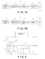
- FIGS. 1A and 1B are block diagrams illustrating a marine electric propulsion system (an electric propulsion system for ships) according to an embodiment of the invention.
- a marine electric propulsion system 1 of the embodiment includes a variable speed engine 2, a synchronous generator 3, a pole conversion unit 4, a synchronous motor 5 or an induction motor 6, and a fixed-pitch propeller 7.
- the marine electric propulsion system in FIG. 1A includes the variable speed engine 2, the synchronous generator 3, the pole conversion unit 4, the synchronous motor 5, and the fixed-pitch propeller 7.
- the marine electric propulsion system in FIG. 1B includes the variable speed engine 2, the synchronous generator 3, the pole conversion unit 4, the induction motor 6, and the fixed-pitch propeller 7.
- variable speed engine 2 is designed to be able to generate output in a moderate combustion state in a rotation region having a constant width.
- the synchronous generator 3 is driven by the variable speed engine 2 to generate the electricity.
- the synchronous motor 5 or the induction motor 6 is electrically connected to the synchronous generator 3 and rotated and driven at a variable speed according to the electric frequency of the synchronous generator 3.
- the pole conversion unit 4 converts the number of poles of the synchronous motor 5 or the induction motor 6. For example, when the number of poles of the synchronous motor 5 or the induction motor 6 is converted from 6 poles to 12 poles, the number of rotations of the synchronous motor 5 or the induction motor 6 becomes half by the electricity having the same frequency, and therefore the rotating speed of the fixed-pitch propeller 7 is reduced by half.
- the pole conversion unit 4 can be removed when the output region of the variable speed engine 2 can be designed to fit to the speed of dead slow or less.
- the frequency of the electricity generated by the synchronous generator 3 changes according to the number of rotations of the variable speed engine 2, and the number of rotations of the synchronous motor 5 or the induction motor 6 is controlled to adjust the rotating speed of the fixed-pitch propeller 7, which allows the desired ship speed to be obtained.
- the synchronous motor 5 or the induction motor 6 may be electrically reversed. That is, going astern can be achieved by flipping a switch, and the necessity of the mechanical reversing mechanism is eliminated.
- the output region of the variable speed engine 2 is set so as to adapt to the ship speed of dead slow or less. Therefore, the marine electric propulsion system 1 can adapt to the ship speed of dead slow or less by controlling the number of rotations of the variable speed engine 2.
- the marine electric propulsion system 1 also includes the pole conversion unit 4. Therefore, because the number of poles of the synchronous motor 5 or the induction motor 6 is converted by the pole conversion unit 4 while the number of rotations of the variable speed engine 2 is kept constant, the rotation of further dead slow can be obtained to perform delicate ship maneuvering in coming alongside the pier or leaving the pier.
- the torque margin means a capacity that can maintain the number of rotations even if a load fluctuates.
- the marine electric propulsion system suitable to a large-diameter propeller and an ice breaking ship can be obtained by the increased torque margin.
- the space for the propulsion device can be minimized to improve the cargo capacity of the ship.
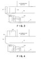
- FIG. 2 illustrates a configuration structure of the marine electric propulsion system of the embodiment.
- FIG. 2 illustrates a stern portion of the ship.
- the variable speed engine 2 and the synchronous generator 3 are disposed above a keel 8 near the stern, the synchronous motor 5 or the induction motor 6 is disposed in an outboard pod 9, and the fixed-pitch propeller 7 is attached to the outboard pod 9 so as to be driven by the synchronous motor 5 or the induction motor 6.
- above the keel includes both the case of an upper surface of the keel and the case of a surface of some sort of support above the keel from the vertical viewpoint.
- An auxiliary generator 10 can be provided in a stern projecting portion 11 in order to generate general-use electricity of the ship.
- variable speed engine 2 and the synchronous generator 3 are formed into a compact package unit as much as possible, and the electricity generated by the variable speed engine 2 and synchronous generator 3 is sent to the synchronous motor 5 or the induction motor 6 in the outboard pod 9 through a cable (not illustrated) to drive the synchronous motor 5 or the induction motor 6, and then drive the fixed-pitch propeller 7.
- variable speed engine 2 and the synchronous generator 3 can be placed in the stern as much as possible because the shafting system is eliminated between the engine and the propeller, a second deck 12 can maximally be utilized because only the auxiliary generator 10 is disposed in the stern projecting portion 11 on the second deck 12, and the space for the propulsion device is minimized in the ship to largely improve the cargo capacity of the ship because the synchronous motor 5 or the induction motor 6 is disposed in the outboard pod 9.
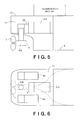
- FIGS. 3 and 4 illustrate other configuration structures of the marine electric propulsion system of the embodiment.
- variable speed engine 2 and the synchronous generator 3 are disposed in the stern projecting portion 11, the synchronous motor 5 or the induction motor 6 is disposed on the keel 8 near the stern, and the fixed-pitch propeller 7 is driven by the synchronous motor 5 or the induction motor 6.
- the configuration structure in FIG. 4 is similar to that in FIG. 3 except that the variable speed engine 2 and the synchronous generator 3 are disposed on an upper deck 13 near the stern.
- variable speed engine 2 and the synchronous generator 3 can be disposed in any position, and therefore the cargo volume can be maximized on the bottom deck while the cargo space of the ship is freely designed.
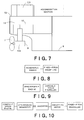
- FIGS. 5 and 6 illustrate still other configuration structures of the marine electric propulsion system of the embodiment.
- FIG. 5 illustrates a side face of the stern portion
- FIG. 6 illustrates a plane of the stern portion of the same configuration structure.
- variable speed engine 2 and the synchronous generator 3 are disposed in the stern projecting portion 11, the synchronous motor 5 or the induction motor 6 is disposed in the outboard pod 9, and the fixed-pitch propeller 7 is driven by the synchronous motor 5 or the induction motor 6.
- variable speed engine 2 and the synchronous generator 3 are disposed in the stern projecting portion 11, and the synchronous motor 5 or the induction motor 6 is disposed in the outboard pod 9, which allows the cargo volume to be maximized.
- FIG. 7 illustrates still another configuration structure of the marine electric propulsion system of the embodiment.
- the configuration structure in FIG. 7 is similar to that in FIG. 5 except that the variable speed engine 2 and the synchronous generator 3 are disposed on the upper deck 13 near the stern.
- variable speed engine 2 and the synchronous generator 3 are disposed on the upper deck 13 near the stern, and the synchronous motor 5 or the induction motor 6 is disposed in the outboard pod 9, which allows the cargo volume to be maximized.
Landscapes
- Chemical & Material Sciences (AREA)
- Engineering & Computer Science (AREA)
- Combustion & Propulsion (AREA)
- Mechanical Engineering (AREA)
- Ocean & Marine Engineering (AREA)
- Control Of Eletrric Generators (AREA)
- Connection Of Motors, Electrical Generators, Mechanical Devices, And The Like (AREA)
Applications Claiming Priority (1)
| Application Number | Priority Date | Filing Date | Title |
|---|---|---|---|
| JP2009090056A JP2010241194A (ja) | 2009-04-02 | 2009-04-02 | 船舶用電気推進システム |
Publications (2)
| Publication Number | Publication Date |
|---|---|
| EP2236409A2 true EP2236409A2 (de) | 2010-10-06 |
| EP2236409A3 EP2236409A3 (de) | 2012-10-03 |
Family
ID=42340863
Family Applications (1)
| Application Number | Title | Priority Date | Filing Date |
|---|---|---|---|
| EP10158673A Withdrawn EP2236409A3 (de) | 2009-04-02 | 2010-03-31 | Elektrisches Schiffsantriebssystem |
Country Status (3)
| Country | Link |
|---|---|
| EP (1) | EP2236409A3 (de) |
| JP (1) | JP2010241194A (de) |
| CN (1) | CN101857082A (de) |
Cited By (7)
| Publication number | Priority date | Publication date | Assignee | Title |
|---|---|---|---|---|
| WO2012089846A1 (en) * | 2010-12-31 | 2012-07-05 | Abb Oy | Propulsion system |
| ITPC20120018A1 (it) * | 2012-06-21 | 2013-12-22 | R T N S R L | Sistema di propulsione elettrica ausiliaria, in particolare per imbarcazioni |
| RU2622175C1 (ru) * | 2015-12-25 | 2017-06-13 | Общество с ограниченной ответственностью "Научно-инженерная компания "Объектные системы автоматики" (ООО "НИК "ОСА") | Электромеханический привод гребного винта судна |
| US10094274B2 (en) | 2015-02-03 | 2018-10-09 | Williams International Co., L.L.C. | Turbo-electric turbo-compounding system |
| CN111674515A (zh) * | 2020-07-03 | 2020-09-18 | 中国船舶工业集团公司第七0八研究所 | 破冰型大型航标船 |
| US11105259B2 (en) | 2015-02-03 | 2021-08-31 | Williams International Co., L.L.C. | Turbo-electric turbo-compounding method |
| US11105258B2 (en) | 2015-02-03 | 2021-08-31 | Williams International Co., L.L.C. | Turbo-electric turbo-compounding system |
Families Citing this family (10)
| Publication number | Priority date | Publication date | Assignee | Title |
|---|---|---|---|---|
| JP5461679B1 (ja) * | 2012-09-25 | 2014-04-02 | ダイハツディーゼル株式会社 | 船舶用電気推進装置 |
| JP6298967B2 (ja) * | 2013-04-17 | 2018-03-28 | 国立研究開発法人 海上・港湾・航空技術研究所 | 電気推進船用周波数変換装置及び電気推進船 |
| CN103287562B (zh) * | 2013-06-07 | 2016-02-24 | 哈尔滨耦合动力工程技术中心有限公司 | 柴油机发电机电动机集成的船舶混合动力系统及混合方法 |
| JP6162086B2 (ja) * | 2014-09-02 | 2017-07-12 | 三井造船株式会社 | 浮体式洋上設備、及び、浮体式洋上設備の電力供給方法 |
| RU2658762C1 (ru) * | 2017-04-06 | 2018-06-26 | Федеральное государственное унитарное предприятие "Крыловский государственный научный центр" | Электроэнергетическая установка судна |
| CN107867384B (zh) * | 2017-10-28 | 2019-07-26 | 中车永济电机有限公司 | 5000吨内河运输船用电推进系统 |
| JP6679113B2 (ja) * | 2018-05-10 | 2020-04-15 | 国立研究開発法人 海上・港湾・航空技術研究所 | 電気推進船の制御装置、電気推進船の制御システム、及び電気推進船 |
| RU2693745C1 (ru) * | 2018-09-11 | 2019-07-04 | Федеральное государственное унитарное предприятие "Крыловский государственный научный центр" | Электроэнергетическая установка судна с системой электродвижения |
| CN109625222B (zh) * | 2018-12-27 | 2020-10-13 | 自然资源部第一海洋研究所 | 一种具有吊舱式电力推进系统的科考船 |
| CN109625223B (zh) * | 2018-12-27 | 2020-10-13 | 自然资源部第一海洋研究所 | 一种吊舱式全回转船舶电力推进系统 |
Citations (5)
| Publication number | Priority date | Publication date | Assignee | Title |
|---|---|---|---|---|
| GB190919871A (en) * | 1909-08-30 | 1910-07-07 | British Thomson Houston Co Ltd | Improvements relating to the Propulsion of Ships. |
| GB191512361A (en) * | 1915-08-27 | 1916-08-17 | British Thomson Houston Co Ltd | Improvements in and relating to Systems of Electric Ship Propulsion. |
| GB147029A (en) * | 1917-05-31 | 1921-11-07 | British Thomson Houston Co Ltd | Improvements in and relating to electric systems for the transmission of power and to multispeed induction motors suitable for use therein |
| FR664720A (fr) * | 1927-11-01 | 1929-09-06 | Thomson Houston Comp Francaise | Perfectionnements aux systèmes de transmission d'énergie notamment pour la propulsion électrique des navires |
| GB458508A (en) * | 1934-05-19 | 1936-12-16 | Westinghouse Electric & Mfg Co | Improvements in or relating to electric power systems |
Family Cites Families (12)
| Publication number | Priority date | Publication date | Assignee | Title |
|---|---|---|---|---|
| DE74327C (de) * | J. J. HEIL MANN in Paris | Wasserfahrzeug mit elektrischem Antrieb | ||
| GB190929250A (en) * | 1909-12-14 | 1910-12-01 | British Thomson Houston Co Ltd | Improvements in and relating to Systems of Ship Propulsion. |
| GB191029250A (en) * | 1910-12-16 | 1911-09-07 | Oskar Beinlich | Improved Hamster Trap. |
| GB188009A (en) * | 1922-03-13 | 1922-11-09 | Robert Macgregor | Electrically propelled ships |
| US2182644A (en) * | 1937-11-06 | 1939-12-05 | Westinghouse Electric & Mfg Co | Ship propulsion |
| JPS6310738U (de) * | 1986-07-03 | 1988-01-23 | ||
| US5417597A (en) * | 1994-04-28 | 1995-05-23 | The United States Of America As Represented By The Secretary Of The Navy | Vessel with machinery modules outside watertight hull |
| JPH08207893A (ja) * | 1995-02-08 | 1996-08-13 | Ishikawajima Harima Heavy Ind Co Ltd | 船舶用の電気推進装置 |
| JPH11285291A (ja) * | 1998-03-27 | 1999-10-15 | Hitachi Zosen Corp | 船舶の電気推進設備 |
| JP2001001991A (ja) * | 1999-06-16 | 2001-01-09 | Mitsubishi Heavy Ind Ltd | フィン付きアジマスプロペラ装置 |
| DE69921432T2 (de) * | 1998-12-21 | 2006-03-02 | Mitsubishi Heavy Industries, Ltd. | Azimuth-Propellervorrichtung |
| JP4664094B2 (ja) * | 2005-03-02 | 2011-04-06 | ヤンマー株式会社 | 船舶用電気推進装置 |
-
2009
- 2009-04-02 JP JP2009090056A patent/JP2010241194A/ja active Pending
-
2010
- 2010-03-31 EP EP10158673A patent/EP2236409A3/de not_active Withdrawn
- 2010-04-01 CN CN201010162739A patent/CN101857082A/zh active Pending
Patent Citations (5)
| Publication number | Priority date | Publication date | Assignee | Title |
|---|---|---|---|---|
| GB190919871A (en) * | 1909-08-30 | 1910-07-07 | British Thomson Houston Co Ltd | Improvements relating to the Propulsion of Ships. |
| GB191512361A (en) * | 1915-08-27 | 1916-08-17 | British Thomson Houston Co Ltd | Improvements in and relating to Systems of Electric Ship Propulsion. |
| GB147029A (en) * | 1917-05-31 | 1921-11-07 | British Thomson Houston Co Ltd | Improvements in and relating to electric systems for the transmission of power and to multispeed induction motors suitable for use therein |
| FR664720A (fr) * | 1927-11-01 | 1929-09-06 | Thomson Houston Comp Francaise | Perfectionnements aux systèmes de transmission d'énergie notamment pour la propulsion électrique des navires |
| GB458508A (en) * | 1934-05-19 | 1936-12-16 | Westinghouse Electric & Mfg Co | Improvements in or relating to electric power systems |
Cited By (8)
| Publication number | Priority date | Publication date | Assignee | Title |
|---|---|---|---|---|
| WO2012089846A1 (en) * | 2010-12-31 | 2012-07-05 | Abb Oy | Propulsion system |
| RU2544268C2 (ru) * | 2010-12-31 | 2015-03-20 | Абб Ой | Движительная система |
| ITPC20120018A1 (it) * | 2012-06-21 | 2013-12-22 | R T N S R L | Sistema di propulsione elettrica ausiliaria, in particolare per imbarcazioni |
| US10094274B2 (en) | 2015-02-03 | 2018-10-09 | Williams International Co., L.L.C. | Turbo-electric turbo-compounding system |
| US11105259B2 (en) | 2015-02-03 | 2021-08-31 | Williams International Co., L.L.C. | Turbo-electric turbo-compounding method |
| US11105258B2 (en) | 2015-02-03 | 2021-08-31 | Williams International Co., L.L.C. | Turbo-electric turbo-compounding system |
| RU2622175C1 (ru) * | 2015-12-25 | 2017-06-13 | Общество с ограниченной ответственностью "Научно-инженерная компания "Объектные системы автоматики" (ООО "НИК "ОСА") | Электромеханический привод гребного винта судна |
| CN111674515A (zh) * | 2020-07-03 | 2020-09-18 | 中国船舶工业集团公司第七0八研究所 | 破冰型大型航标船 |
Also Published As
| Publication number | Publication date |
|---|---|
| CN101857082A (zh) | 2010-10-13 |
| JP2010241194A (ja) | 2010-10-28 |
| EP2236409A3 (de) | 2012-10-03 |
Similar Documents
| Publication | Publication Date | Title |
|---|---|---|
| EP2236409A2 (de) | Elektrisches Schiffsantriebssystem | |
| US9580160B2 (en) | Ship drive system having a plurality of electric drive shafts | |
| US9650120B2 (en) | Electric drive shaft and vehicle comprising such an electric drive shaft | |
| US3619632A (en) | Outboard generator unit for sailboats | |
| JP5164042B2 (ja) | 船舶エネルギーシステム | |
| EP3243736B1 (de) | Schiffsantriebssystem, schiff und schiffsantriebsverfahren | |
| EP2658773B1 (de) | Antriebssystem | |
| JP2004530588A (ja) | 海洋関連対象物のための駆動装置 | |
| JP3902157B2 (ja) | 船舶推進装置_ | |
| JP2001270495A (ja) | 船舶の推進装置および駆動制御方法 | |
| EP1488503B1 (de) | System und verfahren zum bremsen eines motors einer antriebseinheit | |
| SE1300360A1 (sv) | Sätt och anordning vid en drivlina för båtar och fartyg | |
| CN201793007U (zh) | 全电动360°全回转对转桨推进装置 | |
| RU2392180C1 (ru) | Гребная электрическая установка (варианты) | |
| CN107745794A (zh) | 一种安静节能型混合动力系统 | |
| JP2007284018A (ja) | 船舶用ハイブリッド推進システム | |
| JP6298967B2 (ja) | 電気推進船用周波数変換装置及び電気推進船 | |
| JP4452932B2 (ja) | 船舶用電気推進システム | |
| CN116729611A (zh) | 一种破冰船的混合式动力与推进系统 | |
| CN208683087U (zh) | 船舶的动力装置及船舶 | |
| CN2494315Y (zh) | 船用电力变频推进装置 | |
| RU2392179C1 (ru) | Электрическая гребная установка (варианты) | |
| Herdzik | Application possibilities of electric driven propulsion of multi-mode ships | |
| van Eijnatteri | Electric Thruster | |
| JPS60211514A (ja) | 船舶の軸発電装置 |
Legal Events
| Date | Code | Title | Description |
|---|---|---|---|
| PUAI | Public reference made under article 153(3) epc to a published international application that has entered the european phase |
Free format text: ORIGINAL CODE: 0009012 |
|
| AK | Designated contracting states |
Kind code of ref document: A2 Designated state(s): AT BE BG CH CY CZ DE DK EE ES FI FR GB GR HR HU IE IS IT LI LT LU LV MC MK MT NL NO PL PT RO SE SI SK SM TR |
|
| AX | Request for extension of the european patent |
Extension state: AL BA ME RS |
|
| PUAL | Search report despatched |
Free format text: ORIGINAL CODE: 0009013 |
|
| AK | Designated contracting states |
Kind code of ref document: A3 Designated state(s): AT BE BG CH CY CZ DE DK EE ES FI FR GB GR HR HU IE IS IT LI LT LU LV MC MK MT NL NO PL PT RO SE SI SK SM TR |
|
| AX | Request for extension of the european patent |
Extension state: AL BA ME RS |
|
| RIC1 | Information provided on ipc code assigned before grant |
Ipc: B63H 23/24 20060101AFI20120828BHEP Ipc: B63H 21/17 20060101ALI20120828BHEP Ipc: B63J 3/04 20060101ALI20120828BHEP |
|
| 17P | Request for examination filed |
Effective date: 20130328 |
|
| 17Q | First examination report despatched |
Effective date: 20130603 |
|
| STAA | Information on the status of an ep patent application or granted ep patent |
Free format text: STATUS: THE APPLICATION IS DEEMED TO BE WITHDRAWN |
|
| 18D | Application deemed to be withdrawn |
Effective date: 20131214 |