EP2236675A2 - Barrière composée d'éléments de barrière et méthode de connexion et de déconnexion d'éléments de barrière entre eux - Google Patents
Barrière composée d'éléments de barrière et méthode de connexion et de déconnexion d'éléments de barrière entre eux Download PDFInfo
- Publication number
- EP2236675A2 EP2236675A2 EP10159083A EP10159083A EP2236675A2 EP 2236675 A2 EP2236675 A2 EP 2236675A2 EP 10159083 A EP10159083 A EP 10159083A EP 10159083 A EP10159083 A EP 10159083A EP 2236675 A2 EP2236675 A2 EP 2236675A2
- Authority
- EP
- European Patent Office
- Prior art keywords
- barrier
- connecting member
- barrier element
- anchoring
- slot
- Prior art date
- Legal status (The legal status is an assumption and is not a legal conclusion. Google has not performed a legal analysis and makes no representation as to the accuracy of the status listed.)
- Withdrawn
Links
- 230000004888 barrier function Effects 0.000 title claims abstract description 162
- 238000000034 method Methods 0.000 title claims abstract description 23
- 238000004873 anchoring Methods 0.000 claims abstract description 81
- 230000002787 reinforcement Effects 0.000 claims abstract description 10
- 230000008719 thickening Effects 0.000 claims description 39
- 230000003028 elevating effect Effects 0.000 claims description 9
- 230000003014 reinforcing effect Effects 0.000 claims description 5
- 230000007613 environmental effect Effects 0.000 abstract description 2
- ORQBXQOJMQIAOY-UHFFFAOYSA-N nobelium Chemical compound [No] ORQBXQOJMQIAOY-UHFFFAOYSA-N 0.000 description 26
- 229910000831 Steel Inorganic materials 0.000 description 15
- 239000010959 steel Substances 0.000 description 15
- 239000000463 material Substances 0.000 description 12
- 238000005728 strengthening Methods 0.000 description 9
- 230000001681 protective effect Effects 0.000 description 4
- 239000002184 metal Substances 0.000 description 3
- 239000010426 asphalt Substances 0.000 description 2
- 238000005266 casting Methods 0.000 description 2
- 238000010586 diagram Methods 0.000 description 2
- 239000007787 solid Substances 0.000 description 2
- 239000004575 stone Substances 0.000 description 2
- XLYOFNOQVPJJNP-UHFFFAOYSA-N water Substances O XLYOFNOQVPJJNP-UHFFFAOYSA-N 0.000 description 2
- 238000003466 welding Methods 0.000 description 2
- 238000005452 bending Methods 0.000 description 1
- 230000015572 biosynthetic process Effects 0.000 description 1
- 230000007797 corrosion Effects 0.000 description 1
- 238000005260 corrosion Methods 0.000 description 1
- 230000001419 dependent effect Effects 0.000 description 1
- 230000006866 deterioration Effects 0.000 description 1
- 235000000396 iron Nutrition 0.000 description 1
- 238000004519 manufacturing process Methods 0.000 description 1
- 230000001459 mortal effect Effects 0.000 description 1
- 239000010813 municipal solid waste Substances 0.000 description 1
Images


Classifications
-
- E—FIXED CONSTRUCTIONS
- E01—CONSTRUCTION OF ROADS, RAILWAYS, OR BRIDGES
- E01F—ADDITIONAL WORK, SUCH AS EQUIPPING ROADS OR THE CONSTRUCTION OF PLATFORMS, HELICOPTER LANDING STAGES, SIGNS, SNOW FENCES, OR THE LIKE
- E01F15/00—Safety arrangements for slowing, redirecting or stopping errant vehicles, e.g. guard posts or bollards; Arrangements for reducing damage to roadside structures due to vehicular impact
- E01F15/02—Continuous barriers extending along roads or between traffic lanes
- E01F15/08—Continuous barriers extending along roads or between traffic lanes essentially made of walls or wall-like elements ; Cable-linked blocks
-
- E—FIXED CONSTRUCTIONS
- E01—CONSTRUCTION OF ROADS, RAILWAYS, OR BRIDGES
- E01F—ADDITIONAL WORK, SUCH AS EQUIPPING ROADS OR THE CONSTRUCTION OF PLATFORMS, HELICOPTER LANDING STAGES, SIGNS, SNOW FENCES, OR THE LIKE
- E01F15/00—Safety arrangements for slowing, redirecting or stopping errant vehicles, e.g. guard posts or bollards; Arrangements for reducing damage to roadside structures due to vehicular impact
- E01F15/02—Continuous barriers extending along roads or between traffic lanes
- E01F15/08—Continuous barriers extending along roads or between traffic lanes essentially made of walls or wall-like elements ; Cable-linked blocks
- E01F15/088—Details of element connection
-
- E—FIXED CONSTRUCTIONS
- E01—CONSTRUCTION OF ROADS, RAILWAYS, OR BRIDGES
- E01F—ADDITIONAL WORK, SUCH AS EQUIPPING ROADS OR THE CONSTRUCTION OF PLATFORMS, HELICOPTER LANDING STAGES, SIGNS, SNOW FENCES, OR THE LIKE
- E01F15/00—Safety arrangements for slowing, redirecting or stopping errant vehicles, e.g. guard posts or bollards; Arrangements for reducing damage to roadside structures due to vehicular impact
- E01F15/02—Continuous barriers extending along roads or between traffic lanes
- E01F15/08—Continuous barriers extending along roads or between traffic lanes essentially made of walls or wall-like elements ; Cable-linked blocks
- E01F15/081—Continuous barriers extending along roads or between traffic lanes essentially made of walls or wall-like elements ; Cable-linked blocks characterised by the use of a specific material
- E01F15/083—Continuous barriers extending along roads or between traffic lanes essentially made of walls or wall-like elements ; Cable-linked blocks characterised by the use of a specific material using concrete
Definitions
- the object of the invention is a method for connecting barrier elements together and disconnecting barrier elements from each other and a barrier placing in a side of a roadway comprising of barrier elements.
- the object of the invention is defined in the preambles of the independent claims.
- the road barriers can be used for separating lanes leading to different directions in order to prevent meeting accidents, as well as in the side of roads for preventing swerving from the road.
- the experiences collected over years has led to guidelines, with which are aimed to steer the vehicle in accident along the barrier as safely as possible, preventing the vehicle to fall over the barrier or to dart back to the driving lane.
- Steel structured barriers are well known and their design problems concern to discontinuity of the structure; horizontal structured barrier is connected to an upright bar at specified distance. In an accident situation the darting of the vehicle back to the driving lane depends on the distance of the bars, the stiffness of the horizontal structured barrier and the bar connection thereof.
- the steel structured bars are more rigid than horizontal structures and when a car hits to the bar it easily darts back to the drive lane without control. If the car falls to its side before hitting the barrier, the bars can shear inside the car with mortal results.
- concrete barriers have certain advantage over the steel barriers. Due to the absence of the upright bars the continuous concrete barrier is safer than the steel barrier.
- the concrete barrier is mountable straight to the surface of a road or to the shoulder of a road without a foundation, while the bars of the steel barrier have to be pushed into the ground.
- the continuity of the concrete barrier is achieved by connecting single barrier elements together with sufficiently rigid connecting member. In collision situation the concrete barrier acts as a chain, which moves to aside, and wherein the link in the chain are the elements and the connecting members, as well as the meetings between the elements acting as joints with certain stiffness.
- the concrete barrier structures has been developed in recent decades, in order to provide better mountability, dismantlement and remounting, if necessary, so that the traffic safety can be ensured in a collision situation.
- Such inventions are presented in publications e.g. EP0589073 , EP0715026 , EP0826833 , EP1650353 and FR2862673 .
- Common to these inventions is that there are anchoring parts in the end of the elements forming a top-open slots or grooves.
- the adjacent anchoring parts are connected together with a connecting member, which has hooks or T-shaped end thickenings at the ends of the member.
- a top-open slot weakens the strength of the concrete end in environmental conditions with humidity and temperature variations of the both sides of zero Celsius degree.
- a top-open slot has to be jointed or shield plugged in order to prevent frost damages. If the slot is formed only to the upper part, the connecting member has to be pressed into place either manually or mechanically, so on the behalf of mounting, the joint clearance must be large enough, which in turn affects negatively the impact sustainability of large vehicles. If the slot is formed as continuous from the top to the ground, the moisture can be led away from the bottom and take advantage of the element's own weight in mounting, basically, but in practice, leaves and other trash may be flocked in such an open slot structure, which may finally prevent the free flow of water out of the slot and, when the water freezes, may cause cracks to the barrier element, which reduce the structure of the barrier element and the impact sustainability thereof. In addition, in this type of slot structure is forced to use more corrosion protected steel, which makes this solution expensive to implement.
- the objective of the invention is to improve driving safety by presenting a new kind of road barrier consisting of barrier elements, by means of which the foregoing problems can be eliminated or they can be significantly alleviated.
- One object of the invention is to create a barrier, which, compared to previously known solutions, is more resistant to varying weather conditions, and in which the impact sustainability of the interconnections are in the requested level.
- One object is also to provide a method, in which both the connecting and disconnecting of barrier elements is quick and easy.
- the objects of the invention are achieved with a solution, wherein the barrier elements are connected to each other with a connecting member, which connecting member is placed in an anchoring part of the barrier element through a slot part formed to the barrier elements and is fastened in the anchoring part with a fastening means.
- the barrier elements are also easily disconnectable by removing the fastening means, in which case the elements can be exchanged or transferred and reconnect.
- a barrier according to the invention is characterized by the features disclosed in a corresponding claim 1.
- a method according to the invention for connecting two barrier elements together with the connecting member is characterized by the features disclosed in a corresponding claim 8.
- a method according to the invention for disconnecting two barrier elements from each other is characterized by the features disclosed in a corresponding claim 13.
- connection structure of the barrier elements can endure without breaking collisions of large vehicles.
- the barrier element according to the invention and the connection member thereof is easy and inexpensive to manufacture and simply to mount. The possibility to disconnect the elements may provide savings also when, for example in collision situation, only the damaged parts can be replaced with new ones and leave the undamaged elements in place.
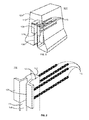
- Fig. 1 depicts, as a perspective view, a barrier element according to the invention.
- the barrier element 102 comprises at least an element part 104, a slot part 106 formed at least another end of the barrier element, an anchoring part 108 formed in the slot part, which anchoring part 108 is preferably attached to the element part 104 with longitudinal reinforcing parts 110 and which anchoring part 108 is formed to the barrier element 102 so that the element part 104 extends over the top of the anchoring part 108 forming a shield for the anchoring part 108.
- a ceiling part 112 may be attached on the top of the anchoring part 108.
- a connecting member led through the slot part 106 to the anchoring part 108, may be fastened in the anchoring part 108 with fastening means 114.
- the shape, height and width of the barrier element 102 may vary depending on the intended use, but the barrier element 102 shown in Figure 1 , is similar to a protective barrier for roadway according to Finnish regulations.
- the height of such barrier element may be, for example, about 900 mm or 1000 mm and the width, for example, about 4 m and 8 m.
- the element part 104 of the barrier element is preferably manufactured from cast stone material, such as concrete, but element part 104 can also be manufactured from other suitable material for the purpose.
- the element part 104 may be solid or it may have been provided with cavities during the casting to reduce the weight of the element part 104.
- the barrier element 102 intended to be a protective barrier must be solid, at least in the parts, which it is reinforced with the reinforcing parts 110 of the anchoring part 108.
- the element part 104 may also be reinforced with longitudinal reinforcement bars, which are anchored with links bent to U-shape, as well as with hook pins and horizontal links. The meaning of the reinforcement is to improve the impact sustainability of the barrier element and to prevent the formation of darting element pieces, for example from the end parts of barrier elements, in a collision situation.
- the slot part 106 is provided to at least another end of the element part 104.
- the slot part 106 is formed to be proceeding substantially vertical position in relation to the barrier element 102, beginning from the bottom of the barrier element 102, but the slot part 106 may also be formed to be proceeding in the barrier element 102 in another angle, for example diagonally in relation to the barrier element 102. In some embodiments, the slot part 106 may also proceed horizontally in relation to barrier element 102. Forms of the slot part are described in connection with Figures 4a-4c .
- the slot part 106 may be closed at its upper end or at its both ends.
- the slot part 106 which is open only at the bottom, is better protected from weather and structural deterioration caused by debris. Different embodiments of the slot part are discussed more closely in context of Figures 5a-5b .
- the slot part 106 is open and widening at the bottom of the element part 104, and the anchoring part 108 is formed in the closed end of the slot part 106.
- FIG. 2 depicts, as a perspective view, an anchoring part 108 according to the invention.
- the anchoring part 108 consists of narrowing parts 126 attached to the slot part 106, which narrowing parts 126 are at least one in the slot part, preferably two, so that in each side wall 122 of the slot part is attached one narrowing part 126 by using well-known attachment methods.
- Narrowing parts 126 may extend from slot part 106 to end part of the element part 104, but it is not necessary. Between the narrowing parts 126 remains a groove having same direction than the slot part 106, which width of the groove is greater than thickness of a plate part 118 of the connecting member shown in Figure 3 , but less than the thickness of the connecting member 116 in the spot of a thickening part 120.
- the narrowing parts 126 extend along the side walls 122 of the slot part at most so deep to the slot part 106 that the thickening part 120 of the connecting member is able to pass in the slot part 106.
- the narrowing parts 126 are preferably rigid and durable material, such as bent steel or angle irons.
- the narrowing parts 126 of the anchoring part may also be connect to one another by means of the ceiling part 112 (as shown e.g. in Fig. 1 ).
- the narrowing parts connected by the ceiling part 112 can distribute forces originated from the collision situation to the whole end structure, which may improve the impact sustainability of the barrier element.
- the size of the ceiling part may vary, but, preferably, its thickness is e.g. about 2 mm - 50 mm and the size of the ceiling part corresponds to both length and width of the narrowing parts.
- Parts such as bent steel panel or plastic or some other corresponding material, improving the guiding of the connecting member 116, may be attached to the slot part 106 in the spot of the anchoring part 108 (not shown).
- the anchoring part 108 is attached by the reinforcement parts 110 to the aggregate material of the element part 104 or the material, from which the element part 104 is manufactured. This aims to improve the impact sustainability of the barrier element 102.
- the reinforcement parts 110 of the anchoring part are preferably longitudinally attached to the element part 104.
- the reinforcement parts 110 may be, for example, longitudinal reinforcement bars commonly used in concrete elements, which reinforcement bars are bent to U-shape, for example, for anchoring to the element part 104. Reinforcement parts 110 may also be other suitable materials for reinforcing concrete.
- the fastening means 114 are placed below the anchoring part.
- the fastening means are discussed more closely in context of Figures 6a-6c .
- the place of the anchoring part in the element part may vary depending on the purpose of use of the barrier element.
- the anchoring part is placed in the bumper level or higher, in which case the impact sustainability of the barrier may improve and the fall of the barrier element in collision situation may also be prevented.
- the place of the anchoring part in the element part 10 may thus be, for example about between 550 mm - 900 mm from the ground level, also depending on if the barrier element is placed to asphalt for separating lanes or beside the road, in which case the barrier element is approximately 10 cm below the surface of the roadway asphalt set into crushed stone.
- the size of the anchoring part may vary.
- the height of the anchoring part is e.g. about 150 mm - 300 mm in the direction of the slot part and e.g. about 20 mm - 400 mm in lateral direction of the anchoring part.
- the thickness of the narrowing part of the anchoring part may be e.g. about 5 mm - 50 mm.
- the size may vary according to use the anchoring part in some other barrier element than the protective barrier in accordance with Finnish regulations.
- Fig. 3 depicts, as a perspective view, the connecting member 116 according to the invention.
- the connecting member 116 comprises at least one plate part 118 and the thickening parts 120 provided to the two opposite sides of the plate part 118 of the connecting member.
- the plate part 118 is made of durable material, which is suitable for the purpose, such as flat bar steel or other sufficiently durable material, and it has preferably a slab-like form.
- the thickening parts 120 provided at the ends of the plate part 118 may be implemented by attaching a supplementary part, such as a round bar steel or profile steel, in two opposite edge of the plate part 118, or else the plate part 118 and the thickening parts 120 are substantially the same piece, so that the thickening parts 120 provided at the opposite edges of the plate part 118 have been, already in casting stage, made of the same material as the plate part 118.
- the thickening parts 120 are attached to two opposite edges of the plate part 118 in both sides of the plate part 118, but the connecting member 116 can also be implemented so that the thickening parts 120 are only in one side of the plate part 118.
- the thickening parts may also be in different sides of the plate part 118, but in opposite edges, however.
- the thickening parts 120 of the connecting member 116 may be higher than the plate part 118 either in one or in both edges. In this way the connecting member can be prevented to lean when mounting it.
- the thickening parts 120 can be e.g. 1-5 cm higher than the plate part 118. If the thickening parts 120 are higher than the plate part 118 only in another edge of the connecting member 116, so when mounting, this side of the connecting member 116 is set first to the slot part so that the higher thickening parts 120 are upwards in the slot part.
- the upper ends of the thickening parts 120 can also be beveled to facilitate the leading of the connecting member 116 to the anchoring part. The beveling of the upper edges can be made either to the thickening part 120 in the both edges or only in another edge of the connecting member 116.
- the length of the connecting member 116 may respond to the length of the anchoring part 108 or it can be shorter or longer.
- the connecting member 116 can also be as high as the slot part 106 extending to the ground level of the barrier element 102, in which case the fastening means 114 are not needed.
- the width of the connecting member may be e.g. about 100 mm - 300 mm, in which case the barrier elements 102 and the connecting member 116 act as a protective barrier.
- the length of the connecting member 116 does not need to be restricted, but in some embodiments the connecting member 116 can be as wide as the barrier element 102, for example, in which case a steel railing coated with element part 104 is formed from the connecting member 116 and the barrier elements 102.
- the connecting member 116 and the barrier elements 102 can form combinations of steel railing and concrete barrier, which can be useful, for example in places, where the barrier elements should be able to dismantle quickly.
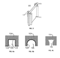
- Figs. 4a-4c depict various forms of a slot part 106.
- the slot part 106 is preferably formed, while welding, to the element part 104 with a site piece, which is removed from the slot part 106 after welding.
- the walls 122 of the slot part can be strengthened with strengthening parts, for example steel or sheet metal strips, such as in Figs. 4a and 4b .
- Either the side wall(s) 122 of the slot part can be strengthened or the back wall 124 of the slot part is strengthened or both the side wall(s) 122 and the back wall 124 are strengthened.
- the slot part may consist of different materials, for example so that the side and back walls 122 and 124 are e.g. sheet metal and/or steel in spot of the anchoring part 108 and elsewhere the walls 122 and 124 of the slot part are not strengthened, such as in Fig. 4c .
- the whole slot part 106 may also be remained without strengthening.
- the form of the slot parts 106 provided in the element part 104 may also vary.
- the slot part 106 may be, for example, as a top view, angular ( Fig. 4a ) or U-shaped ( Fig. 4b ) or some other appropriate form, such as a form widening towards the bottom of the slot ( Fig. 4c ).
- the strips used for strengthening the side walls 122 of the slot part may extend, e.g. about 3 cm, over the edges of the slot part 106 to the end part of the element part 104, such as in Fig. 4a .
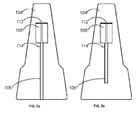
- Figs. 5a and 5b depict, as a front view, various ways of implementation of the slot part.
- the length and the width of the slot part 106 may vary depending on an embodiment.
- the slot part 106 may extend from the bottom of the barrier element 102 to the anchoring part 108 ( Fig. 5a ) or the slot part 106 may extend only a short way just below the anchoring part 108 ( Fig. 5b ).
- the length of the slot part 106 below the anchoring part 108 has to be at least as long as the length of the connecting member 116, so that the connecting member 116 could be led to the slot part 106 and thereout.
- At least some part of the slot part 106 has to be wider than the width of the connecting member 116 in the spot of the thickening parts 120, but the slot part 106 must be sufficiently narrow at the spot of the anchoring part 108, so that the width of the slot remaining between the narrowing parts 126 does not exceed the thickness of the connecting member in the spot of the thickening parts 120.
- the slot part 106 which is wider than the connecting member 116 in the spot of the thickening parts 120, enables the leading of the connecting member 116 to the slot part 106 and from the slot part 106.
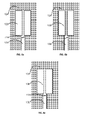
- Figs. 6a-6c depict various fastening means 114 for fastening the connecting member 116 in the barrier element 102 in embodiments, wherein the connecting member 116 is approximately as high as the anchoring part 108. Means placed fixedly to the barrier element or separate fastening means can be used as fastening means 114.
- the piece, such as a thin plate part, used for strengthening the side walls of the slot part is used for fastening, to which piece has been made a cross cut below the anchoring part 108. While fastening the connecting member, the piece 114 used for strengthening is bent under the connecting member to keep the connecting member in its place. Said cross cut can also be made either to one of the side walls or both of the side walls of the slot part 106, in which case either one or both of the pieces 114 can be bent under the connecting member in order to fastening it. If the slot part 106 has totally remained without strengthening, the fastening means 114 can be attached straight to the slot part 106, for example, by same way as the strengthening part is attached to the slot part 106.
- the fastening means 114 are attached to the piece used for strengthening the side walls of the slot part either so that a cavity sized of the fastening means 114 has been provided to the slot part 106 or the slot part 106 is selected to be wide enough that the connecting member with its thickening parts fits to pass to the anchoring part 108 over the fastening means 114.
- fastening means 114 can be used, for example, sheet metal or some other adequate material, which is sufficiently rigid to keep the connecting member in the anchoring part 108, but which can be bent to the slot part 106 without heavy tools.
- the wall of the slot part may be strengthened, in which case the fastening means 114 are attached to the strengthening part of the slot part, or the fastening means 114 are attached straight to the wall of the slot part.
- Fig. 6c is an example of separate fastening means.
- a spring pin which is set in the slot part 106, can be used as separate fastening means.
- In the walls of the slot part can be made holes for the pin, to which holes the pin is set.
- Separate fastening means 114 can be, for example, a magnet or a screw or some other corresponding part, which is placed in the slot part 106 to fasten the connecting member to the anchoring part 108.
- Fig. 7 depicts, as a top view, one connection of the connecting member 116 to anchoring part of element parts 104 according to the invention.
- the narrowing parts 126 of the anchoring part keep the thickening parts 120 of the connecting member 116 connected to the anchoring part in lateral direction of barrier elements.
- the connecting member 116 may be, for example, as high as the slot part or about as high as the anchoring part.
- the height of the connecting member 116 corresponds about the height of the anchoring part 108.
- the slot part 106 may be a slot part 106 in accordant with Fig. 5b with both ends closed.
- the connecting member 116 is led to the anchoring part 108 through the slot part 106 and is fastened to the anchoring part 108 with the fastening means 114.
- the connecting member 116 is fixedly connected with the reinforcing parts 110 from one end to the first element part 104.
- the thickening parts 120 are formed only to the open end of the connecting member 116.
- Two kinds of barrier elements can be in this embodiment; in another barrier element 102 the connecting member 116 is fixedly connected to both ends of the element part 104 and in the other barrier element 102 the slot part are formed to both ends of the barrier element, or the slot part is in another end of the element part 104 and fixed connecting member 116 is in the other end.
- the slot part formed to the other element is preferably bottom-open.
- the barrier elements 102 are connected to each other by elevating upwards the second element and placing the slot part of the second element in the thickening part 120 of the connecting member 116 of the first element.
- the connecting member 116 fixedly connected to the first element part comes into the anchoring part of the second element part.
- the fastening means are not needed in this embodiment, because the connecting member 116 is fixedly connected to the first element part 104. If there are two types of barrier element according to embodiment in Fig. 9 ; equipped with the fixed connecting member and equipped with slot parts, the dismantlement of the barrier elements is taken place by elevating the barrier element equipped with slot parts upwards from the point, where the barrier is desired to be dismantle.
- Figs. 10a and 10b are method diagrams of steps of a connecting method and a disconnecting method according to the invention.
- the first thickening part 120 of the connecting member 116 is placed in the slot part 106 of the first barrier element 102.
- a measure is performed for leading the connecting member 116 through the slot part 106 of the first barrier element 102 to the anchoring part 108 either by lowering the first barrier element 102 down to ground level or by elevating the connecting member 118 through the slot part 106 upwards. If the leading of the connecting member 116 to the anchoring part 108 is carried out by elevating the connecting member 116 upwards, then the fastening of the connecting member 116 to the anchoring part 108 is performed with the fastening means 114. At step 906, a measure is performed for placing second thickening part 120 of the connecting member 116 in the slot part.
- the measure is performed by elevating either the first or the second barrier element 102 upwards from the ground level to place the second thickening part 120 in the slot part 106 of the second barrier element.
- a measure is performed for leading the connecting member through the slot part of the second barrier element to the anchoring part 108 of the second barrier element.
- the measure is performed by lowering either the first or the second barrier element 102 down the ground level, in which case the connecting member 116 elevates/lowers through the slot part 106 of the second barrier element to the anchoring part 108 of the second barrier element.
- a measure is performed for releasing the first thickening part 120 of the connecting member 116 from the anchoring part 108 of the first barrier element 102. If, in fastening stage, is performed the fastening of the connecting member 116 to the anchoring part 108 with the fastening means, the measure will be performed by releasing the fastening means 114 by using appropriate tool, for example, for bending or knocking off the fastening means bent to the slot. If some separate fastening means, for example a spring pin, is selected for fastening means, it can be snap out from its fastening grooves by using some suitable tool. In other cases, the measure is performed by elevating the first barrier element 102 upwards from the ground level.
- the measure is performed for releasing the second thickening part 120 of the connecting member 116 from the anchoring part 108 of the second barrier element either by leading the connecting member 116, through the slot part 106 of the barrier elements, from the anchoring parts 108 or by elevating the first or the second barrier element 102 from the ground level, in order to release the connecting member 116 from the anchoring part 108 of the second barrier element 102.
Landscapes
- Engineering & Computer Science (AREA)
- Architecture (AREA)
- Civil Engineering (AREA)
- Structural Engineering (AREA)
- Road Paving Structures (AREA)
- Bridges Or Land Bridges (AREA)
- Refuge Islands, Traffic Blockers, Or Guard Fence (AREA)
Applications Claiming Priority (1)
| Application Number | Priority Date | Filing Date | Title |
|---|---|---|---|
| FI20095368A FI128216B (fi) | 2009-04-03 | 2009-04-03 | Ajotien reunaan tai kaistoja erottamaan asetettava kaide sekä menetelmät kaide-elementtien kiinnittämiseksi toisiinsa ja irrottamiseksi toisistaan |
Publications (2)
| Publication Number | Publication Date |
|---|---|
| EP2236675A2 true EP2236675A2 (fr) | 2010-10-06 |
| EP2236675A3 EP2236675A3 (fr) | 2014-01-01 |
Family
ID=40590251
Family Applications (1)
| Application Number | Title | Priority Date | Filing Date |
|---|---|---|---|
| EP10159083.4A Withdrawn EP2236675A3 (fr) | 2009-04-03 | 2010-04-06 | Barrière composée d'éléments de barrière et méthode de connexion et de déconnexion d'éléments de barrière entre eux |
Country Status (2)
| Country | Link |
|---|---|
| EP (1) | EP2236675A3 (fr) |
| FI (1) | FI128216B (fr) |
Cited By (3)
| Publication number | Priority date | Publication date | Assignee | Title |
|---|---|---|---|---|
| EP2682526A3 (fr) * | 2012-07-07 | 2015-12-16 | Strabag Ag | Elément de délimitation de la voie de circulation |
| EP3088609A1 (fr) * | 2015-04-27 | 2016-11-02 | Anstar Oy | Agencement de fixation pour éléments de barrière et élément de barrière |
| CN107974936A (zh) * | 2016-10-27 | 2018-05-01 | 成都亚联科科技有限公司 | 一种桥梁路面用组件 |
Citations (5)
| Publication number | Priority date | Publication date | Assignee | Title |
|---|---|---|---|---|
| EP0589073A1 (fr) | 1989-07-25 | 1994-03-30 | Rodney I. Smith | Barrière de sécurité routière enchaînée |
| EP0715026A1 (fr) | 1994-12-01 | 1996-06-05 | Ballast Nedam Beton en Waterbouw B.V. | Elément séparateur transposable, séparateur ainsi formé et méthode |
| EP0826833A2 (fr) | 1996-08-28 | 1998-03-04 | Hermann Spengler KG | Bloc séparateur pour voies de circulation |
| FR2862673A1 (fr) | 2003-11-21 | 2005-05-27 | Saint Gobain Stradal | Bloc allonge formant barriere telle qu'une barriere de securite pour voie de circulation routiere |
| EP1650353A2 (fr) | 2000-01-27 | 2006-04-26 | Maba Fertigteilindustrie GmbH | Élement de paroi en béton pour barrière de sécurité routière |
Family Cites Families (4)
| Publication number | Priority date | Publication date | Assignee | Title |
|---|---|---|---|---|
| DE2331168A1 (de) * | 1973-06-19 | 1975-01-16 | Peter Dipl Ing Bofinger | Verkettungsschloss fuer vorgefertigte betonleitplanken |
| DE3733846A1 (de) * | 1987-10-07 | 1989-04-27 | Reiff Beton Rohr Gmbh & Co Kg | Trennvorrichtung |
| EP0641893B1 (fr) * | 1993-09-07 | 1997-08-06 | Peter Rausch | Barrière routière en béton |
| FR2783535B3 (fr) * | 1998-09-18 | 2000-12-01 | Georges Bukiatme | Element de protection pour chantier et barriere de protection pour chantier correspondante |
-
2009
- 2009-04-03 FI FI20095368A patent/FI128216B/fi active IP Right Grant
-
2010
- 2010-04-06 EP EP10159083.4A patent/EP2236675A3/fr not_active Withdrawn
Patent Citations (5)
| Publication number | Priority date | Publication date | Assignee | Title |
|---|---|---|---|---|
| EP0589073A1 (fr) | 1989-07-25 | 1994-03-30 | Rodney I. Smith | Barrière de sécurité routière enchaînée |
| EP0715026A1 (fr) | 1994-12-01 | 1996-06-05 | Ballast Nedam Beton en Waterbouw B.V. | Elément séparateur transposable, séparateur ainsi formé et méthode |
| EP0826833A2 (fr) | 1996-08-28 | 1998-03-04 | Hermann Spengler KG | Bloc séparateur pour voies de circulation |
| EP1650353A2 (fr) | 2000-01-27 | 2006-04-26 | Maba Fertigteilindustrie GmbH | Élement de paroi en béton pour barrière de sécurité routière |
| FR2862673A1 (fr) | 2003-11-21 | 2005-05-27 | Saint Gobain Stradal | Bloc allonge formant barriere telle qu'une barriere de securite pour voie de circulation routiere |
Cited By (4)
| Publication number | Priority date | Publication date | Assignee | Title |
|---|---|---|---|---|
| EP2682526A3 (fr) * | 2012-07-07 | 2015-12-16 | Strabag Ag | Elément de délimitation de la voie de circulation |
| EP3088609A1 (fr) * | 2015-04-27 | 2016-11-02 | Anstar Oy | Agencement de fixation pour éléments de barrière et élément de barrière |
| CN107974936A (zh) * | 2016-10-27 | 2018-05-01 | 成都亚联科科技有限公司 | 一种桥梁路面用组件 |
| CN107974936B (zh) * | 2016-10-27 | 2019-12-27 | 广东省怡合建设有限公司 | 一种桥梁路面用组件 |
Also Published As
| Publication number | Publication date |
|---|---|
| FI128216B (fi) | 2019-12-31 |
| FI20095368A7 (fi) | 2010-10-04 |
| FI20095368L (fi) | 2010-10-04 |
| EP2236675A3 (fr) | 2014-01-01 |
| FI20095368A0 (fi) | 2009-04-03 |
Similar Documents
| Publication | Publication Date | Title |
|---|---|---|
| AU738850B2 (en) | Crash barrier and barrier elements | |
| EP2384381B1 (fr) | Poteau | |
| CA2634087C (fr) | Systeme ameliore de barrieres modulaires pour autoroute | |
| EP3277885B1 (fr) | Glissière de sécurité routière avec écarteur | |
| EP0575705A1 (fr) | Barrière métallique de sécurité | |
| KR101083269B1 (ko) | 차량 방호 울타리 | |
| FI128216B (fi) | Ajotien reunaan tai kaistoja erottamaan asetettava kaide sekä menetelmät kaide-elementtien kiinnittämiseksi toisiinsa ja irrottamiseksi toisistaan | |
| EP0310754A2 (fr) | Dispositif de séparation | |
| JPS6012484B2 (ja) | 道路保護障壁 | |
| US7226237B2 (en) | Road barrier | |
| DE102008026661B4 (de) | Verkehrsleitwand | |
| EP2333160B1 (fr) | Dispositif de guidage de la circulation | |
| DE102015113034A1 (de) | Rückhaltesystem, insbesondere aus Beton, und Verfahren zu dessen Herstellung | |
| EP2894257B1 (fr) | Système de protection pour éviter des obstacles dans les caniveaux des routes | |
| KR102902996B1 (ko) | 개폐 동작 안정도가 향상된 상향개폐식 비상회차로 차단기 | |
| FI126295B (fi) | Kaide | |
| FI128718B (fi) | Kiinnitysjärjestely kaide-elementtien kiinnittämiseksi ja kaide | |
| CN220521131U (zh) | 一种防落雪的声屏障 | |
| JP7072821B2 (ja) | 離間型スノーシェルター | |
| FI12035U1 (fi) | Kiinnitysjärjestely kaide-elementtien kiinnittämiseksi ja kaide | |
| RU160344U1 (ru) | Железобетонное парапетное ограждение с предварительным напряжением | |
| RU2283913C1 (ru) | Дорожное железобетонное ограждение | |
| EP2513376B1 (fr) | Configuration de chaussée | |
| AT524699A1 (de) | Leitwandelement | |
| IT202100015191A1 (it) | Barriera stradale |
Legal Events
| Date | Code | Title | Description |
|---|---|---|---|
| PUAI | Public reference made under article 153(3) epc to a published international application that has entered the european phase |
Free format text: ORIGINAL CODE: 0009012 |
|
| AK | Designated contracting states |
Kind code of ref document: A2 Designated state(s): AT BE BG CH CY CZ DE DK EE ES FI FR GB GR HR HU IE IS IT LI LT LU LV MC MK MT NL NO PL PT RO SE SI SK SM TR |
|
| AX | Request for extension of the european patent |
Extension state: AL BA ME RS |
|
| PUAL | Search report despatched |
Free format text: ORIGINAL CODE: 0009013 |
|
| AK | Designated contracting states |
Kind code of ref document: A3 Designated state(s): AT BE BG CH CY CZ DE DK EE ES FI FR GB GR HR HU IE IS IT LI LT LU LV MC MK MT NL NO PL PT RO SE SI SK SM TR |
|
| AX | Request for extension of the european patent |
Extension state: AL BA ME RS |
|
| RIC1 | Information provided on ipc code assigned before grant |
Ipc: E01F 15/08 20060101AFI20131122BHEP |
|
| STAA | Information on the status of an ep patent application or granted ep patent |
Free format text: STATUS: THE APPLICATION IS DEEMED TO BE WITHDRAWN |
|
| 18D | Application deemed to be withdrawn |
Effective date: 20140702 |