EP2236678A2 - Löffel für die Behandlung von ausgegrabenen Boden, Baumaschine ausgestattet mit dem besagten Löffel, und Verfahren für die Behandlung von ausgegrabenen Boden mit dem besagten Löffel. - Google Patents
Löffel für die Behandlung von ausgegrabenen Boden, Baumaschine ausgestattet mit dem besagten Löffel, und Verfahren für die Behandlung von ausgegrabenen Boden mit dem besagten Löffel. Download PDFInfo
- Publication number
- EP2236678A2 EP2236678A2 EP10158576A EP10158576A EP2236678A2 EP 2236678 A2 EP2236678 A2 EP 2236678A2 EP 10158576 A EP10158576 A EP 10158576A EP 10158576 A EP10158576 A EP 10158576A EP 2236678 A2 EP2236678 A2 EP 2236678A2
- Authority
- EP
- European Patent Office
- Prior art keywords
- bucket
- soil
- devices
- binder
- binders
- Prior art date
- Legal status (The legal status is an assumption and is not a legal conclusion. Google has not performed a legal analysis and makes no representation as to the accuracy of the status listed.)
- Granted
Links
Images

Classifications
-
- E—FIXED CONSTRUCTIONS
- E02—HYDRAULIC ENGINEERING; FOUNDATIONS; SOIL SHIFTING
- E02F—DREDGING; SOIL-SHIFTING
- E02F7/00—Equipment for conveying or separating excavated material
- E02F7/06—Delivery chutes or screening plants or mixing plants mounted on dredgers or excavators
-
- E—FIXED CONSTRUCTIONS
- E02—HYDRAULIC ENGINEERING; FOUNDATIONS; SOIL SHIFTING
- E02F—DREDGING; SOIL-SHIFTING
- E02F3/00—Dredgers; Soil-shifting machines
- E02F3/04—Dredgers; Soil-shifting machines mechanically-driven
- E02F3/28—Dredgers; Soil-shifting machines mechanically-driven with digging tools mounted on a dipper- or bucket-arm, i.e. there is either one arm or a pair of arms, e.g. dippers, buckets
- E02F3/36—Component parts
- E02F3/40—Dippers; Buckets ; Grab devices, e.g. manufacturing processes for buckets, form, geometry or material of buckets
- E02F3/402—Dippers; Buckets ; Grab devices, e.g. manufacturing processes for buckets, form, geometry or material of buckets with means for facilitating the loading thereof, e.g. conveyors
- E02F3/405—Dippers; Buckets ; Grab devices, e.g. manufacturing processes for buckets, form, geometry or material of buckets with means for facilitating the loading thereof, e.g. conveyors using vibrating means
-
- E—FIXED CONSTRUCTIONS
- E02—HYDRAULIC ENGINEERING; FOUNDATIONS; SOIL SHIFTING
- E02F—DREDGING; SOIL-SHIFTING
- E02F3/00—Dredgers; Soil-shifting machines
- E02F3/04—Dredgers; Soil-shifting machines mechanically-driven
- E02F3/28—Dredgers; Soil-shifting machines mechanically-driven with digging tools mounted on a dipper- or bucket-arm, i.e. there is either one arm or a pair of arms, e.g. dippers, buckets
- E02F3/36—Component parts
- E02F3/40—Dippers; Buckets ; Grab devices, e.g. manufacturing processes for buckets, form, geometry or material of buckets
- E02F3/407—Dippers; Buckets ; Grab devices, e.g. manufacturing processes for buckets, form, geometry or material of buckets with ejecting or other unloading device
Definitions
- This invention relates to a method for treating excavated soil. Said method is particularly suitable for the laying and underground laying of pipelines, stabilization of road foundations or reclaiming of polluted soils.
- This invention also relates to a special bucket for earthworks necessary to carry out the above-mentioned method and to an earthwork machine including such bucket.
- Such procedure is usually carried out by laying a certain quantity of binding material onto the soil to treat and the subsequent use of a special machine equipped with a toothed drum that mills and mixes soil with binder.
- the latter is previously laid off on the surface to a certain depth, on average 40-50 cm, depending on the dimensions and positioning of the drum.
- the known technique envisages the laying of binder on top of the excavated heaps and the subsequent working of soil by means of an excavator or a loader, provided with a screening bucket.
- the action of the screening devices positioned inside the bucket results in a good mixing of soil and binder.
- one of the known techniques uses a loader provided with screening bucket inside which the gathered soil is mixed with a binder contained in a pressure container. Furthermore, two pipes, one delivering the binder from the container to bucket and one linking the pressure container to the compressed air unit, brake the loader.
- Such known solution is also equipped with a control system including a time-controlled valve, positioned on the delivering pipe, which injects only a predetermined quantity of binder.
- this known technique presents an important drawback: the quantity of binder sent to the bucket is not directly linked to the real quantity of soil in the bucket, because it derives from the estimation of the operator on board the loader. Moreover, this technique presents the additional drawback that the binder is placed on top of the material in the bucket. This makes the mixing of the two little effective, if we do not work the material many times by gathering and screening it with several working cycles.
- the pressure container can contain only one type of binder. Consequently, if several binders are necessary, their mixture must be carried out previously in another container.
- the present invention aims at overcoming the above-mentioned drawbacks pertaining to the known technique.
- the target of the present invention is to obtain a homogeneous mixture of soil and binder with a unique screening cycle, which would considerably reduce working time.
- Another target of the present invention is the use of the correct quantity of binder, or mixtures of binders, according to the real quantity of soil to treat.
- Yet another target of the present invention is to save more time, compared to the known similar techniques, and to reach a better efficiency, by using a mixture of several types of binders, simultaneously injected, in preset quantities, into the material inside the bucket.
- the screening bucket for earthworks is equipped with a loading compartment in which the soil is loaded and with screening devices positioned inside said compartment.
- said bucket includes special devices (dosage devices) which deliver the right quantity of binding material, positioned inside said loading compartment. Said devices deliver the binding material directly into the soil inside the bucket.
- the present invention produces then a homogeneous mixture of soil and binder with a unique screening cycle. This considerably reduces working time. Moreover, it is possible to deliver in a constant way the correct quantity of binder, or mixtures of binders, according to the real quantity of soil.
- the dosage devices include an injection chamber and injection devices of the binder, positioned longitudinally next to the screening devices. Consequently, the binder, or mixtures of binders, is directly injected into the soil, all along the front part of bucket, and is not placed on top of soil, as is the case, on the contrary, for the known technique.
- said injection devices are placed in parallel with the screening devices.
- the injection chamber presents ribs which make the distribution of binder or binding mixtures more uniform along said injection devices.
- the bucket is associated with a computer which communicates with a control unit. Said systems control and regulate the quantity of binder delivered by dosage devices according to the type and/or humidity of the soil.
- the bucket includes, or is associated with, primary valve means, controlled by a computer, which regulate the delivery of one or more binders.
- the bucket includes, or is associated with, secondary valve means, controlled by the computer, which regulate the input of a transport fluid, normally compressed air, to transport binders and to enable their mixing.
- a transport fluid normally compressed air
- the bucket is associated with, or envisages, weight measurement devices, which send to the computer the exact weight of soil loaded in the loading compartment of the bucket.
- the weight measurement devices are linked to the devices regulating the movements and position of the boom and turret controlling the bucket.
- said weight measurement devices are regulated by a software loaded in an electronic terminal, positioned in the machine that operates the bucket, normally an excavator, and are in communication with the control unit.
- the control unit according to preset parameters, associates to a certain weight certain levels and delivery times of binders and transport fluid. Such data are received and used by the computer operating said valves.
- said dosage devices are connected to a pressure tank through a totally or partially flexible pipe.
- the tank contains one or more binders.
- part of said pipe delivering binders or binding mixtures is stiff, next to the bucket, to prevent damage when in use. Such stiff part is linked to the remaining pipe through a rapid joint.
- said tank can be divided into several compartments to contain different binders separately. Therefore, the different binders are premixed, through above-mentioned transport fluid, in the delivery pipe before being injected into the soil.
- the bucket includes devices delivering a fluid which reduces the amount of dust caused by injection of binding materials into the loading compartment.
- This invention also includes an earthwork machine equipped with a screening bucket, as illustrated above.
- the earthwork machine is linked to a tank which contains one or more binding materials.
- this invention includes one method for treating excavated soil which envisages the following phases:
- a pre-mixing of several different binders inside the delivery pipe linked to the bucket is envisaged.
- the mixtures of binders are injected in the bucket simultaneously with the mixing of different types of binders, contained in a tank, directly inside the pipe delivering binders into the bucket.
- the injection of the binder into bucket is proportional to the real weight of the soil measured during the weighing operation.
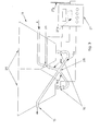
- a bucket 10 is particularly suitable for a hydraulic excavator 17, equipped with wheels 17a for linear movement and with a turret 17b rotating around a vertical axis Y, as shown by arrow in fig. 1 .
- Said turret 17b is linked to a boom 17c equipped with a stick 17f to operate bucket 10.
- Hydraulic excavator 17 could also be equipped with tracks instead of wheels 17a.
- hydraulic excavator 17 is more efficient in that it reduces obstruction and can be used on limited areas, given its 360° rotating capacity.
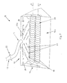
- Bucket 10 presents internally a loading compartment 10a open on top in which, normally, the soil (generally heaps of excavated soil) is gathered to be screened.
- the soil generally heaps of excavated soil
- bucket 10 Inside loading compartment 10a, particularly in its inferior part, bucket 10 includes screening devices 24, for example rollers equipped with blades and counter blades, operated by a motor rotating around axis X to screen soil. The soil, once screened, comes out from the inferior opening of loading compartment 10a of bucket 10.
- screening devices 24 for example rollers equipped with blades and counter blades, operated by a motor rotating around axis X to screen soil. The soil, once screened, comes out from the inferior opening of loading compartment 10a of bucket 10.
- the above-mentioned bucket is equipped with a dosage device 12 of binding material, positioned directly inside loading compartment 10a.
- Bucket 10 is associated with pipe 13, totally or partially flexible to follow the movements of boom 17c and stick 17f which deliver the binder itself.
- Said pipe is linked to boom 17c and in communication with above-mentioned dosage device 12.
- dosage device 12 of binding material includes, inside loading compartment 10a, an injection chamber 12a, delimited by two plates, one at the front and one at the back. Said chamber is adjacent to the part of bucket 10 nearest to hydraulic excavator 17. Pipe 13 delivering binder is then connected into superior part.
- Dosage device 12 includes also an injection mouth 18 opening on the inferior part of injection chamber 12a, through which binder is directly injected into soil, not on its surface, during the screening process. As a result, the mixture soil-binder is more homogeneous.
- injection mouth 18 develops all along the length of bucket 10, in parallel with rotation axis X, that is with the screening devices 24.
- Injection chamber 12a is characterised by internal ribs 23 on its internal walls in order to distribute the injected material homogeneously all along the length of injection mouth 18. Moreover, said internal ribs 23 make the whole structure more rigid.
- injection mouth 18 in some embodiments 4-6 mm wide, is sufficiently narrow to prevent stoppage of dosage device 12 and is protected by two projecting elements.
- Injection chamber 12a gradually widens in order to inject binder all along length of bucket 10.
- Pipe 13 presents, in some embodiments, a rigid element 11 linked to bucket 10 on one side and to the remaining part of pipe 13 on the other, through a rapid joint 20. Said element 11 connects injection chamber 12a to delivery pipe 13.
- Dosage device 12 described above is positioned inside loading compartment 10a of bucket 10 and linked to this through fixing devices, specifically gussets 19 and bolts, to remove it if not in use and to clean it.
- the binder is directly injected into the material inside bucket 10 next to screening devices 24. This helps to obtain a homogeneous mixing of soil and binder during the whole screening cycle.
- pipe 13 is linked to boom 17c and stick 17f of hydraulic excavator 17.
- Hydraulic excavator 17 is linked to a pressure tank 14 with several compartments 25, in this case only two, preferably but not necessarily positioned on wheels 14c in order to be hooked and towed by excavator 17. Delivery pipe 13 comes out from tank 14.
- Said tank 14 is linked to a compressor unit 15 which is structured to guarantee a binder flow towards bucket 10 of approximately 3-7% in weight proportionally to the flow of screened soil (for example 6,000 l/min). Such percentage can obviously vary depending on the characteristics and degree of humidity of soil and on the result we want to obtain in terms of stabilization or simply improvement of the soil.
- Tank 14 is also equipped with valves 16 in every compartment 25 in which it is divided, with electrical servo control system with stepper motor, operated by the electronic control unit 27.
- This unit is radio controlled by means of a transceiver antenna 27a and of a radio unit 27b and can be linked to tank 14 ( fig. 3 ). Through antenna 27a and the radio unit 27b the control unit 27 can be in communication with computer 17d positioned in the rotating turret 17b where the operator operates bucket 10 and hydraulic excavator 17.
- Excavator 17 is equipped with a weight measurement system for the soil gathered in bucket 10. It includes a weight measurement device 30, positioned on cylinders of boom 7c, which measures the pressure of cylinder oil. Then, it sends a signal, proportioned to the weight of material inside bucket 10, to computer 17d.
- two other devices are envisaged: one which measures position 31 and one movement 32.
- Device 31 is positioned on pivot 17f and device 32 is positioned in correspondence with joint between boom 17c and turret 17b.
- Said devices measure respectively the reciprocal inclination of stick 17f with boom 17c and of boom 17c with turret 17b.
- the computer 17d is equipped with a software to process signals received by above-mentioned devices 30, 31 and 32.
- the signals taken by devices 31 and 32 and sent to computer 17d are elaborated with the oil pressure signal of the cylinders, taken by weighing device 30, and computer 17d calculates the weight of the gathered material by a series of algorithms. Such values are then used to control valves 16 that deliver binder.
- Such computer 17d is equipped with memory devices 17e and a special software which calculate the weight of gathered material and manage the injection process.
- the above-mentioned software according to preset values memorized by said memory devices 17e, controls the opening levels and times of valves 16, according to the weight inside the bucket 10.
- the weight measuring device 30 interacts, through said software and a radio control, with control unit 27 which controls the opening of valves 16 in tank 14. This way we constantly obtain the right quantity of binder, or mixtures of binders, according to the real quantity of soil to work.
- each valve 16 is determined autonomously according to preset values loaded in the software, according to the real weight of soil inside bucket 10.
- the separate delivering pipes 16a, positioned under valves 16, converge in a point 28 together with another pipe 26a delivering compressed air, shown by arrow A.
- This pipe is controlled by valve 26 which is servo controlled and linked to computer 27.
- the compressed air transports binders to dosage device 12. Thanks to the compressed air flow and the simultaneous opening of valves 16 and 26, the binders contained in the compartments of tank 14 are mixed in the right percentages, according to the different opening levels of valve 16, directly inside pipe 13 which delivers the binder to bucket 10.
- the binders in the case of a stabilization process, can be in powder (such as calcium oxide and/or cement) and the different mixing percentage is determined by the type of soil and its humidity degree. So, according to preset values loaded in the software, we will have different opening levels and opening times of valves 16 and 26.
- hydraulic excavator 17 gathers the soil to be screened in the bucket 10.
- computer 17d calculates the weight of the collected material and calculates, according to the type of soil and its degree of humidity, the opening levels and opening times of valves 16 and 26 which are sent to control unit 27. Said unit then operates and coordinates valves 16 and 26.
- the screening devices 24 and the injection of binders directly into the gathered soil are operated, either simultaneously or in a sequence.
- the material is screened, mixed homogeneously to the correct quantity of binder and laid down in the digging, ready to be tamped.
- This technique is considerably time saving compared to similar known techniques and improves their efficiency through the mixing of several binders, according to predetermined values, simultaneously with their injection into the gathered material in bucket 10. It also avoids the need for another tank to premix the binders.
- the height of tank 14 and the form and position of the loading openings, as shown in fig. 1 (reference number 14a), can enable the loading of the binders directly under the loading mouths for silotrailers in traditional stocking plants. This avoids the need for special silotrailers on the workplace to transport binders.
- tank 14 as shown in fig. 1 , is positioned on wheels and towed by a machine (in our case a hydraulic excavator 17) can guarantee its operating autonomy for the whole working day. This further improves the efficiency of the system, compared to the known methods.
- Said button is preferably, but not necessarily, positioned on one of the two joysticks which enable the operator to control the movements of hydraulic excavator 17 from turret 17b.
- Said joysticks are associated with computer 17d.
- the material is screened, homogeneously mixed with the right quantity of binder(s) and laid down in the correct point, ready to be tamped.
- the described method to treat excavated soil can be conveniently used to fill diggings, by recycling directly on place the excavated soil, for example in the case of road foundations, or to lay pipes underground.
- said method is suitable for the reclamation of lands containing polluting agents, if said agents are to be treated with binders to inhibit the polluting agents, such as calcium oxide.
- the homogeneous mixture of soil and binder can be carried out with only one screening cycle. This considerably reduces working time compared to the known techniques.
- the binder is constantly injected in the right proportion, according to the real quantity of soil to work and not following the estimation of the operator, as in the case of the known techniques.
- a high pressure water circuit which delivers, by means of nebulising nozzles 29 ( fig. 2 ), pressure water to reduce dust generated by the injection of the binder.
- Said nozzles are positioned on the bucket 10, in particular inside loading compartment 10a, preferably on its upper part.
- Such water can also be used in case of particularly dry soil to have always the right humidity percentage suitable for stabilization process.
- Pressurized water is regulated by a delivering valve controlled by the software which manages valves 16 and valve 26.
- the pump which lets in the pressurized water is linked to the compressor unit 15.
- Said pump can be equipped with pistons, for example, with a capacity between 15 and 25 l/min and a pressure between 100 and 300 bar.
- Nozzles 29 are equipped with blades in order to create a water blade which covers the upper opening of bucket 10 uniformly.
- other types of nozzles can be envisaged, for example on the exit mouth of bucket 10 we can have traditional nozzles to eliminate the remaining dust produced when the bucket is emptied.
- the use of nozzles is particularly suitable when working in open spaces, such as the countryside, or where there is no traffic.
- bucket 10 can also include a closing cover, better if removable and made of plastic, hinged to the back side of bucket 10. This way dirty water generated by nozzles produces only little dripping along the external walls of bucket 10.
Landscapes
- Engineering & Computer Science (AREA)
- Mining & Mineral Resources (AREA)
- Mechanical Engineering (AREA)
- Civil Engineering (AREA)
- General Engineering & Computer Science (AREA)
- Structural Engineering (AREA)
- Consolidation Of Soil By Introduction Of Solidifying Substances Into Soil (AREA)
- Shovels (AREA)
- Earth Drilling (AREA)
- Investigation Of Foundation Soil And Reinforcement Of Foundation Soil By Compacting Or Drainage (AREA)
Applications Claiming Priority (1)
| Application Number | Priority Date | Filing Date | Title |
|---|---|---|---|
| IT000071A ITVI20090071A1 (it) | 2009-03-31 | 2009-03-31 | Metodo di riempimento di uno scavo, benna per movimento terra atta a realizzare tale metodo e macchina per movimento terra comprendente tale benna |
Publications (3)
| Publication Number | Publication Date |
|---|---|
| EP2236678A2 true EP2236678A2 (de) | 2010-10-06 |
| EP2236678A3 EP2236678A3 (de) | 2010-11-17 |
| EP2236678B1 EP2236678B1 (de) | 2012-01-18 |
Family
ID=41092215
Family Applications (1)
| Application Number | Title | Priority Date | Filing Date |
|---|---|---|---|
| EP10158576A Not-in-force EP2236678B1 (de) | 2009-03-31 | 2010-03-31 | Löffel für die Behandlung von ausgegrabenen Boden, Baumaschine ausgestattet mit dem besagten Löffel, und Verfahren für die Behandlung von ausgegrabenen Boden mit dem besagten Löffel. |
Country Status (3)
| Country | Link |
|---|---|
| EP (1) | EP2236678B1 (de) |
| AT (1) | ATE541993T1 (de) |
| IT (1) | ITVI20090071A1 (de) |
Cited By (5)
| Publication number | Priority date | Publication date | Assignee | Title |
|---|---|---|---|---|
| ITUD20100220A1 (it) * | 2010-11-29 | 2012-05-30 | Alessandro Foffani | Coltello per un dispositivo di frantumazione e vagliatura del terreno di una benna, di un vaglio fisso od altro, dispositivo di frantumazione e vagliatura del terreno e relativa benna o vaglio fisso |
| JP2016056588A (ja) * | 2014-09-10 | 2016-04-21 | 株式会社エルフホールデイングス | 地盤改良方法および装置 |
| JP2017009148A (ja) * | 2015-06-18 | 2017-01-12 | 雨宮 清 | 地雷対応の分別処理機 |
| WO2021218078A1 (zh) * | 2020-04-30 | 2021-11-04 | 深圳市工勘岩土集团有限公司 | 一种基坑土方运输及破碎处理的施工方法 |
| CN113684875A (zh) * | 2021-07-08 | 2021-11-23 | 浙江中瑞建筑工程有限公司 | 一种软土地层超宽深基坑施工工艺 |
Citations (1)
| Publication number | Priority date | Publication date | Assignee | Title |
|---|---|---|---|---|
| DE19950435C1 (de) | 1999-10-19 | 2001-03-29 | Dietmar Mothes Gmbh Strasen Un | Vorrichtung zum Aufbereiten von Aushubmaterial |
Family Cites Families (13)
| Publication number | Priority date | Publication date | Assignee | Title |
|---|---|---|---|---|
| JPS5988528A (ja) * | 1982-11-10 | 1984-05-22 | Takao Shoji | 地盤改良装置 |
| SE506398C2 (sv) * | 1993-04-16 | 1997-12-08 | Scooper Ab | Kombiskopa för upptagning och sönderdelning av material |
| JPH1054028A (ja) * | 1997-06-02 | 1998-02-24 | Fumio Kinoshita | 攪拌装置付きバケット |
| JP4577601B2 (ja) * | 2001-05-09 | 2010-11-10 | 株式会社エリア・クリエイション | 矢板埋設による窪み形成方法 |
| JP2002371544A (ja) * | 2001-06-14 | 2002-12-26 | Toa Harbor Works Co Ltd | 土砂と固化材の混練方法および装置 |
| DE10131869B4 (de) * | 2001-06-25 | 2008-10-30 | Ernst Josef Kronenberger | Verfahren zur Neutralisierung von Calciumhydroxid Ca(OH)2 in mit Kalk verbesserten Böden zur Verhinderung der puzzolanischen Reaktion |
| JP2004169495A (ja) * | 2002-11-22 | 2004-06-17 | Okada Aiyon Corp | トロンメルバケット |
| JP2004316390A (ja) * | 2003-04-16 | 2004-11-11 | Chowa Kogyo Kk | 土砂の水切り方法、および同水切り装置 |
| JP2005350883A (ja) * | 2004-06-08 | 2005-12-22 | Chowa Kogyo Kk | 土砂の水切り方法、および同装置 |
| DE102005011964B4 (de) * | 2005-03-14 | 2009-12-10 | Schenk, Jürgen | Universalgerät mit Anbauklassierer |
| JP5015493B2 (ja) * | 2006-05-16 | 2012-08-29 | 株式会社福田組 | 地盤改良装置および地盤改良機 |
| JP2007327197A (ja) * | 2006-06-06 | 2007-12-20 | Masayuki Suzuki | 油圧ショベル、油圧ショベル用バケット及び土砂処理方法。 |
| JP4478187B2 (ja) * | 2008-05-13 | 2010-06-09 | 株式会社エルフ | 地盤改良機 |
-
2009
- 2009-03-31 IT IT000071A patent/ITVI20090071A1/it unknown
-
2010
- 2010-03-31 EP EP10158576A patent/EP2236678B1/de not_active Not-in-force
- 2010-03-31 AT AT10158576T patent/ATE541993T1/de active
Patent Citations (1)
| Publication number | Priority date | Publication date | Assignee | Title |
|---|---|---|---|---|
| DE19950435C1 (de) | 1999-10-19 | 2001-03-29 | Dietmar Mothes Gmbh Strasen Un | Vorrichtung zum Aufbereiten von Aushubmaterial |
Cited By (7)
| Publication number | Priority date | Publication date | Assignee | Title |
|---|---|---|---|---|
| ITUD20100220A1 (it) * | 2010-11-29 | 2012-05-30 | Alessandro Foffani | Coltello per un dispositivo di frantumazione e vagliatura del terreno di una benna, di un vaglio fisso od altro, dispositivo di frantumazione e vagliatura del terreno e relativa benna o vaglio fisso |
| EP2458096A1 (de) | 2010-11-29 | 2012-05-30 | Alessandro Foffani | Erdsieb- und Zerkleinerungsvorrichtung für Baggerschaufeln oder stationäre Siebeinrichtungen und dementsprechende Baggerschaufel oder Siebeinrichtung |
| JP2016056588A (ja) * | 2014-09-10 | 2016-04-21 | 株式会社エルフホールデイングス | 地盤改良方法および装置 |
| JP2017009148A (ja) * | 2015-06-18 | 2017-01-12 | 雨宮 清 | 地雷対応の分別処理機 |
| WO2021218078A1 (zh) * | 2020-04-30 | 2021-11-04 | 深圳市工勘岩土集团有限公司 | 一种基坑土方运输及破碎处理的施工方法 |
| CN113684875A (zh) * | 2021-07-08 | 2021-11-23 | 浙江中瑞建筑工程有限公司 | 一种软土地层超宽深基坑施工工艺 |
| CN113684875B (zh) * | 2021-07-08 | 2022-08-23 | 浙江中瑞建筑工程有限公司 | 一种软土地层超宽深基坑施工工艺 |
Also Published As
| Publication number | Publication date |
|---|---|
| ITVI20090071A1 (it) | 2010-10-01 |
| ATE541993T1 (de) | 2012-02-15 |
| EP2236678A3 (de) | 2010-11-17 |
| EP2236678B1 (de) | 2012-01-18 |
Similar Documents
| Publication | Publication Date | Title |
|---|---|---|
| EP2236678B1 (de) | Löffel für die Behandlung von ausgegrabenen Boden, Baumaschine ausgestattet mit dem besagten Löffel, und Verfahren für die Behandlung von ausgegrabenen Boden mit dem besagten Löffel. | |
| US4285598A (en) | Concrete mixing apparatus | |
| AU2001269316B2 (en) | Recycled material and mixing machinery | |
| CN206899521U (zh) | 一种制备流态可固化土的成套设备 | |
| JP3957328B2 (ja) | 土壌を掘削し、埋め戻す装置および方法 | |
| EP1186717A1 (de) | Bewegliche bodenverbesserungsmaschine | |
| KR102632132B1 (ko) | 표층 고화장치 및 이를 이용한 표층 고화공법 | |
| CA2941482C (en) | Batch mode soil improvement | |
| US20160362852A1 (en) | Rotary mixer with a front-mounted additive distributor | |
| CN112024586B (zh) | 污染场地土壤原位固化修复方法 | |
| JP2004536243A (ja) | 再利用された材料混合機械 | |
| JP3344716B2 (ja) | 土質改良用固化材管理システム | |
| KR100920109B1 (ko) | 현장 거치식 배치 플랜트 | |
| CN101128633B (zh) | 土壤特别是水稳定性差的干性土壤的处理方法 | |
| US10718099B2 (en) | Leveling, tune-up and compacting device | |
| CN119736828B (zh) | 一种以水泥为能量剂的路面场拌施工方法 | |
| KR200437478Y1 (ko) | 습식 식생기반재를 이용한 습식 씨앗연속분출장치 | |
| JP3914007B2 (ja) | 法面吹き付け材料の製造方法およびその材料を使用した空気圧送法面吹き付け工法。 | |
| JP3713427B2 (ja) | 自走式土質改良機の固化材制御装置及び自走式土質改良機 | |
| JP2024170847A (ja) | 基盤材処理システム | |
| KR100801528B1 (ko) | 사면용 플랜트 및 그 작동방법 | |
| CN207244626U (zh) | 高海拔地区沥青混凝土心墙坝施工的设备 | |
| JP2000096605A (ja) | 埋め戻し方法及び埋め戻し材製造装置 | |
| CN119320053A (zh) | 一种软土固化精确拌合系统及其拌合方法 | |
| KR200284141Y1 (ko) | 차수용 원료의 혼합장치 |
Legal Events
| Date | Code | Title | Description |
|---|---|---|---|
| PUAI | Public reference made under article 153(3) epc to a published international application that has entered the european phase |
Free format text: ORIGINAL CODE: 0009012 |
|
| AK | Designated contracting states |
Kind code of ref document: A2 Designated state(s): AT BE BG CH CY CZ DE DK EE ES FI FR GB GR HR HU IE IS IT LI LT LU LV MC MK MT NL NO PL PT RO SE SI SK SM TR |
|
| AX | Request for extension of the european patent |
Extension state: AL BA ME RS |
|
| PUAL | Search report despatched |
Free format text: ORIGINAL CODE: 0009013 |
|
| AK | Designated contracting states |
Kind code of ref document: A3 Designated state(s): AT BE BG CH CY CZ DE DK EE ES FI FR GB GR HR HU IE IS IT LI LT LU LV MC MK MT NL NO PL PT RO SE SI SK SM TR |
|
| AX | Request for extension of the european patent |
Extension state: AL BA ME RS |
|
| 17P | Request for examination filed |
Effective date: 20110517 |
|
| GRAP | Despatch of communication of intention to grant a patent |
Free format text: ORIGINAL CODE: EPIDOSNIGR1 |
|
| RIC1 | Information provided on ipc code assigned before grant |
Ipc: E02F 3/96 20060101ALI20110623BHEP Ipc: E02F 7/06 20060101ALI20110623BHEP Ipc: E02F 3/40 20060101AFI20110623BHEP |
|
| GRAS | Grant fee paid |
Free format text: ORIGINAL CODE: EPIDOSNIGR3 |
|
| GRAA | (expected) grant |
Free format text: ORIGINAL CODE: 0009210 |
|
| AK | Designated contracting states |
Kind code of ref document: B1 Designated state(s): AT BE BG CH CY CZ DE DK EE ES FI FR GB GR HR HU IE IS IT LI LT LU LV MC MK MT NL NO PL PT RO SE SI SK SM TR |
|
| REG | Reference to a national code |
Ref country code: GB Ref legal event code: FG4D |
|
| REG | Reference to a national code |
Ref country code: CH Ref legal event code: EP |
|
| REG | Reference to a national code |
Ref country code: AT Ref legal event code: REF Ref document number: 541993 Country of ref document: AT Kind code of ref document: T Effective date: 20120215 Ref country code: IE Ref legal event code: FG4D |
|
| REG | Reference to a national code |
Ref country code: DE Ref legal event code: R096 Ref document number: 602010000672 Country of ref document: DE Effective date: 20120322 |
|
| REG | Reference to a national code |
Ref country code: NL Ref legal event code: VDEP Effective date: 20120118 |
|
| LTIE | Lt: invalidation of european patent or patent extension |
Effective date: 20120118 |
|
| PG25 | Lapsed in a contracting state [announced via postgrant information from national office to epo] |
Ref country code: BG Free format text: LAPSE BECAUSE OF FAILURE TO SUBMIT A TRANSLATION OF THE DESCRIPTION OR TO PAY THE FEE WITHIN THE PRESCRIBED TIME-LIMIT Effective date: 20120418 Ref country code: BE Free format text: LAPSE BECAUSE OF FAILURE TO SUBMIT A TRANSLATION OF THE DESCRIPTION OR TO PAY THE FEE WITHIN THE PRESCRIBED TIME-LIMIT Effective date: 20120118 Ref country code: IS Free format text: LAPSE BECAUSE OF FAILURE TO SUBMIT A TRANSLATION OF THE DESCRIPTION OR TO PAY THE FEE WITHIN THE PRESCRIBED TIME-LIMIT Effective date: 20120518 Ref country code: NO Free format text: LAPSE BECAUSE OF FAILURE TO SUBMIT A TRANSLATION OF THE DESCRIPTION OR TO PAY THE FEE WITHIN THE PRESCRIBED TIME-LIMIT Effective date: 20120418 Ref country code: HR Free format text: LAPSE BECAUSE OF FAILURE TO SUBMIT A TRANSLATION OF THE DESCRIPTION OR TO PAY THE FEE WITHIN THE PRESCRIBED TIME-LIMIT Effective date: 20120118 Ref country code: NL Free format text: LAPSE BECAUSE OF FAILURE TO SUBMIT A TRANSLATION OF THE DESCRIPTION OR TO PAY THE FEE WITHIN THE PRESCRIBED TIME-LIMIT Effective date: 20120118 Ref country code: LT Free format text: LAPSE BECAUSE OF FAILURE TO SUBMIT A TRANSLATION OF THE DESCRIPTION OR TO PAY THE FEE WITHIN THE PRESCRIBED TIME-LIMIT Effective date: 20120118 |
|
| PG25 | Lapsed in a contracting state [announced via postgrant information from national office to epo] |
Ref country code: LV Free format text: LAPSE BECAUSE OF FAILURE TO SUBMIT A TRANSLATION OF THE DESCRIPTION OR TO PAY THE FEE WITHIN THE PRESCRIBED TIME-LIMIT Effective date: 20120118 Ref country code: PL Free format text: LAPSE BECAUSE OF FAILURE TO SUBMIT A TRANSLATION OF THE DESCRIPTION OR TO PAY THE FEE WITHIN THE PRESCRIBED TIME-LIMIT Effective date: 20120118 Ref country code: GR Free format text: LAPSE BECAUSE OF FAILURE TO SUBMIT A TRANSLATION OF THE DESCRIPTION OR TO PAY THE FEE WITHIN THE PRESCRIBED TIME-LIMIT Effective date: 20120419 Ref country code: FI Free format text: LAPSE BECAUSE OF FAILURE TO SUBMIT A TRANSLATION OF THE DESCRIPTION OR TO PAY THE FEE WITHIN THE PRESCRIBED TIME-LIMIT Effective date: 20120118 Ref country code: PT Free format text: LAPSE BECAUSE OF FAILURE TO SUBMIT A TRANSLATION OF THE DESCRIPTION OR TO PAY THE FEE WITHIN THE PRESCRIBED TIME-LIMIT Effective date: 20120518 |
|
| PG25 | Lapsed in a contracting state [announced via postgrant information from national office to epo] |
Ref country code: CY Free format text: LAPSE BECAUSE OF FAILURE TO SUBMIT A TRANSLATION OF THE DESCRIPTION OR TO PAY THE FEE WITHIN THE PRESCRIBED TIME-LIMIT Effective date: 20120118 |
|
| PG25 | Lapsed in a contracting state [announced via postgrant information from national office to epo] |
Ref country code: SI Free format text: LAPSE BECAUSE OF FAILURE TO SUBMIT A TRANSLATION OF THE DESCRIPTION OR TO PAY THE FEE WITHIN THE PRESCRIBED TIME-LIMIT Effective date: 20120118 Ref country code: SE Free format text: LAPSE BECAUSE OF FAILURE TO SUBMIT A TRANSLATION OF THE DESCRIPTION OR TO PAY THE FEE WITHIN THE PRESCRIBED TIME-LIMIT Effective date: 20120118 Ref country code: CZ Free format text: LAPSE BECAUSE OF FAILURE TO SUBMIT A TRANSLATION OF THE DESCRIPTION OR TO PAY THE FEE WITHIN THE PRESCRIBED TIME-LIMIT Effective date: 20120118 Ref country code: MC Free format text: LAPSE BECAUSE OF NON-PAYMENT OF DUE FEES Effective date: 20120331 Ref country code: DK Free format text: LAPSE BECAUSE OF FAILURE TO SUBMIT A TRANSLATION OF THE DESCRIPTION OR TO PAY THE FEE WITHIN THE PRESCRIBED TIME-LIMIT Effective date: 20120118 Ref country code: EE Free format text: LAPSE BECAUSE OF FAILURE TO SUBMIT A TRANSLATION OF THE DESCRIPTION OR TO PAY THE FEE WITHIN THE PRESCRIBED TIME-LIMIT Effective date: 20120118 Ref country code: RO Free format text: LAPSE BECAUSE OF FAILURE TO SUBMIT A TRANSLATION OF THE DESCRIPTION OR TO PAY THE FEE WITHIN THE PRESCRIBED TIME-LIMIT Effective date: 20120118 |
|
| PLBE | No opposition filed within time limit |
Free format text: ORIGINAL CODE: 0009261 |
|
| STAA | Information on the status of an ep patent application or granted ep patent |
Free format text: STATUS: NO OPPOSITION FILED WITHIN TIME LIMIT |
|
| PG25 | Lapsed in a contracting state [announced via postgrant information from national office to epo] |
Ref country code: SK Free format text: LAPSE BECAUSE OF FAILURE TO SUBMIT A TRANSLATION OF THE DESCRIPTION OR TO PAY THE FEE WITHIN THE PRESCRIBED TIME-LIMIT Effective date: 20120118 |
|
| 26N | No opposition filed |
Effective date: 20121019 |
|
| REG | Reference to a national code |
Ref country code: IE Ref legal event code: MM4A |
|
| PG25 | Lapsed in a contracting state [announced via postgrant information from national office to epo] |
Ref country code: IE Free format text: LAPSE BECAUSE OF NON-PAYMENT OF DUE FEES Effective date: 20120331 |
|
| REG | Reference to a national code |
Ref country code: DE Ref legal event code: R097 Ref document number: 602010000672 Country of ref document: DE Effective date: 20121019 |
|
| PG25 | Lapsed in a contracting state [announced via postgrant information from national office to epo] |
Ref country code: MK Free format text: LAPSE BECAUSE OF FAILURE TO SUBMIT A TRANSLATION OF THE DESCRIPTION OR TO PAY THE FEE WITHIN THE PRESCRIBED TIME-LIMIT Effective date: 20120118 |
|
| PG25 | Lapsed in a contracting state [announced via postgrant information from national office to epo] |
Ref country code: ES Free format text: LAPSE BECAUSE OF FAILURE TO SUBMIT A TRANSLATION OF THE DESCRIPTION OR TO PAY THE FEE WITHIN THE PRESCRIBED TIME-LIMIT Effective date: 20120429 |
|
| PG25 | Lapsed in a contracting state [announced via postgrant information from national office to epo] |
Ref country code: MT Free format text: LAPSE BECAUSE OF FAILURE TO SUBMIT A TRANSLATION OF THE DESCRIPTION OR TO PAY THE FEE WITHIN THE PRESCRIBED TIME-LIMIT Effective date: 20120118 |
|
| PG25 | Lapsed in a contracting state [announced via postgrant information from national office to epo] |
Ref country code: TR Free format text: LAPSE BECAUSE OF FAILURE TO SUBMIT A TRANSLATION OF THE DESCRIPTION OR TO PAY THE FEE WITHIN THE PRESCRIBED TIME-LIMIT Effective date: 20120118 |
|
| PG25 | Lapsed in a contracting state [announced via postgrant information from national office to epo] |
Ref country code: SM Free format text: LAPSE BECAUSE OF FAILURE TO SUBMIT A TRANSLATION OF THE DESCRIPTION OR TO PAY THE FEE WITHIN THE PRESCRIBED TIME-LIMIT Effective date: 20120118 Ref country code: LU Free format text: LAPSE BECAUSE OF NON-PAYMENT OF DUE FEES Effective date: 20120331 |
|
| PG25 | Lapsed in a contracting state [announced via postgrant information from national office to epo] |
Ref country code: HU Free format text: LAPSE BECAUSE OF FAILURE TO SUBMIT A TRANSLATION OF THE DESCRIPTION OR TO PAY THE FEE WITHIN THE PRESCRIBED TIME-LIMIT Effective date: 20100331 |
|
| REG | Reference to a national code |
Ref country code: CH Ref legal event code: PL |
|
| PG25 | Lapsed in a contracting state [announced via postgrant information from national office to epo] |
Ref country code: CH Free format text: LAPSE BECAUSE OF NON-PAYMENT OF DUE FEES Effective date: 20140331 Ref country code: LI Free format text: LAPSE BECAUSE OF NON-PAYMENT OF DUE FEES Effective date: 20140331 |
|
| REG | Reference to a national code |
Ref country code: FR Ref legal event code: PLFP Year of fee payment: 7 |
|
| PGFP | Annual fee paid to national office [announced via postgrant information from national office to epo] |
Ref country code: AT Payment date: 20160322 Year of fee payment: 7 Ref country code: GB Payment date: 20160321 Year of fee payment: 7 Ref country code: FR Payment date: 20160321 Year of fee payment: 7 |
|
| REG | Reference to a national code |
Ref country code: AT Ref legal event code: MM01 Ref document number: 541993 Country of ref document: AT Kind code of ref document: T Effective date: 20170331 |
|
| GBPC | Gb: european patent ceased through non-payment of renewal fee |
Effective date: 20170331 |
|
| REG | Reference to a national code |
Ref country code: FR Ref legal event code: ST Effective date: 20171130 |
|
| PG25 | Lapsed in a contracting state [announced via postgrant information from national office to epo] |
Ref country code: FR Free format text: LAPSE BECAUSE OF NON-PAYMENT OF DUE FEES Effective date: 20170331 Ref country code: AT Free format text: LAPSE BECAUSE OF NON-PAYMENT OF DUE FEES Effective date: 20170331 |
|
| PG25 | Lapsed in a contracting state [announced via postgrant information from national office to epo] |
Ref country code: GB Free format text: LAPSE BECAUSE OF NON-PAYMENT OF DUE FEES Effective date: 20170331 |
|
| PGFP | Annual fee paid to national office [announced via postgrant information from national office to epo] |
Ref country code: DE Payment date: 20240403 Year of fee payment: 15 |
|
| PGFP | Annual fee paid to national office [announced via postgrant information from national office to epo] |
Ref country code: IT Payment date: 20240402 Year of fee payment: 15 |
|
| REG | Reference to a national code |
Ref country code: DE Ref legal event code: R119 Ref document number: 602010000672 Country of ref document: DE |
|
| PG25 | Lapsed in a contracting state [announced via postgrant information from national office to epo] |
Ref country code: DE Free format text: LAPSE BECAUSE OF NON-PAYMENT OF DUE FEES Effective date: 20251001 |
|
| PG25 | Lapsed in a contracting state [announced via postgrant information from national office to epo] |
Ref country code: IT Free format text: LAPSE BECAUSE OF NON-PAYMENT OF DUE FEES Effective date: 20250331 |