EP2236706B1 - Verfahren zur Montage eines Griffs für Treibstangenverschluss an einer Tür oder einem Fenster und der Griff selbst - Google Patents
Verfahren zur Montage eines Griffs für Treibstangenverschluss an einer Tür oder einem Fenster und der Griff selbst Download PDFInfo
- Publication number
- EP2236706B1 EP2236706B1 EP20100156834 EP10156834A EP2236706B1 EP 2236706 B1 EP2236706 B1 EP 2236706B1 EP 20100156834 EP20100156834 EP 20100156834 EP 10156834 A EP10156834 A EP 10156834A EP 2236706 B1 EP2236706 B1 EP 2236706B1
- Authority
- EP
- European Patent Office
- Prior art keywords
- handle
- contact element
- sash
- handle body
- zone
- Prior art date
- Legal status (The legal status is an assumption and is not a legal conclusion. Google has not performed a legal analysis and makes no representation as to the accuracy of the status listed.)
- Active
Links
Images


Classifications
-
- E—FIXED CONSTRUCTIONS
- E05—LOCKS; KEYS; WINDOW OR DOOR FITTINGS; SAFES
- E05B—LOCKS; ACCESSORIES THEREFOR; HANDCUFFS
- E05B9/00—Lock casings or latch-mechanism casings ; Fastening locks or fasteners or parts thereof to the wing
- E05B9/08—Fastening locks or fasteners or parts thereof, e.g. the casings of latch-bolt locks or cylinder locks to the wing
-
- E—FIXED CONSTRUCTIONS
- E05—LOCKS; KEYS; WINDOW OR DOOR FITTINGS; SAFES
- E05B—LOCKS; ACCESSORIES THEREFOR; HANDCUFFS
- E05B15/00—Other details of locks; Parts for engagement by bolts of fastening devices
- E05B15/02—Striking-plates; Keepers; Bolt staples; Escutcheons
-
- E—FIXED CONSTRUCTIONS
- E05—LOCKS; KEYS; WINDOW OR DOOR FITTINGS; SAFES
- E05C—BOLTS OR FASTENING DEVICES FOR WINGS, SPECIALLY FOR DOORS OR WINDOWS
- E05C9/00—Arrangements of simultaneously actuated bolts or other securing devices at well-separated positions on the same wing
- E05C9/04—Arrangements of simultaneously actuated bolts or other securing devices at well-separated positions on the same wing with two sliding bars moved in opposite directions when fastening or unfastening
Definitions
- This invention relates to a method for mounting a cremone handle on a door or window, in particular a door or window with a metal frame, and the respective handle that implements the method.
- Prior art cremone handles comprise a handle body (usually quadrangular in shape or with rounded edges) from which there extend, at one end, the operating handgrip, and, at the other end, the means which actuate the device for closing the door/window (usually one or two bars).
- cremone handle designs have been developed from this basic structure (such as, for example, patent EP-446.566 and utility models IT-227.820 and IT-234.079 , all in the name of this Applicant) in order to adapt the cremone handle to different types of door and window units: bidirectional (right- or left-hand turning) or multipurpose handles, handles with locking handgrip, handles for tilt and turn doors or windows, etc.
- the Applicant devised a multipurpose cremone handle (see patent IT 1.310.347 and the corresponding European publication EP - 1.036.899 ) whose technical and structural characteristics are such as to make the handle reliable and convenient to use, limited in size, and extremely versatile, that is to say, having all the technical and operating features of the traditional cremone handles currently available on the market, extended and adapted to suit awning windows, without altering the handle body.
- cuts must be made on the frame member at the zones where the handle is to be fitted before all the parts of the sash frame (horizontal and vertical members) are assembled to form the sash.
- This operation is necessary to be able to slide a metal block or counterplate into the tubular frame member as far as the slotted zone, the ends of the metal block or counterplate having threaded holes made in them or being provided with plastic inserts in which the holes are made.
- the block is locked in place with the handle or with an external temporary stabilizing element.
- the sash can be assembled and mounted and the handle definitively fitted to it by coupling the fins on the handle with the operating rods on the sash.
- the pins on the fins and the operating rods are coupled by cutting slots in the frame member, in the base of the frame member with the groove and from which there protrude the pins associated with the fins which are inserted into the holes in the rods from the inside to the outside of the tubular chamber.
- the handle comprises a body equipped with a base, applicable to the sash by respective fasteners, connectable to contact elements.
- the contact elements are two contact parts connected by an elastic means.
- the handle body can be mounted as follows.
- the two contact parts are fitted on the base of the body and inserted into the sash.
- a fastener is fastened to the contact element in such a way as to move a part of the contact element into contact with the inside surface of the door / windows, thus provocating the blocking of the handle to the windows / door.
- This invention therefore has for an aim to overcome these disadvantages by providing a method for mounting a cremone handle on doors or windows that is at once practical and fast and allows a high level of locking security and reliability.
- Another aim of the invention is to provide a cremone handle that implements this method with a system for fastening it to the frame member that is practical and secure and reduces assembly times.
- the invention achieves this aim by providing a mounting method, in particular, a method for mounting a cremone handle on a door or window with a metal frame, comprising the technical characteristics set out in one or more of the appended claims.
- the method according to the invention is used to mount a cremone handle for doors and windows, denoted in its entirety by the numeral 1, in particular for awning windows, where the handles must be more limited in size than traditional handles, but have features similar to those of traditional handles (such as tilt and turn operation with incorrect operation safety lock, left-hand and right-hand opening, etc.).
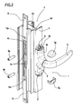
- the door/window which the handle 1 is mounted on has at least one through slot 2 made on a surface 3 of a sash 4 forming part of the door/window of defined thickness S (see Figures 5 and 6 ).
- the handle 1 in turn comprises at least:
- control means 9 comprise a pair of fins 9 protruding from the base 5a, each of which, in use, is provided with a pin 9p that fits into a slot 9a of the corresponding fin 9 after the pin has been inserted into the above mentioned operating means 10, which are in the form of rods slidable in a groove 4c in the sash 4 and each of which is equipped with a through hole 10a.
- the pin 9p, rods 10 and fins 9 are coupled to each thanks to through slots 4s made on the sash 4 and at the bottom of the groove 4c.
- the mounting method according to the invention comprises the following steps:
- Figure 5 shows that, after the second insertion step, there is a step of abutting and positioning the constrained zone 7b of the contact element 7, with the aid of the fastening screw 6, at the end of the slot 4, in such a way that it faces the inside surface 4b of the tubular chamber 4a: this makes it possible to constrain the other zone 7a, without reducing the stability of the handle 1.
- the contact element 7 is held in a position substantially parallel to the handle body 5 (this position being shown in Figure 9 ) thanks to the presence and/or contact with the fins 9, on one side, and, on the other, by a wall 4d forming one side of the tubular chamber 4a.
- the above mentioned step of inserting firstly the unconstrained zone 7a of the contact element 7 occurs by inclining the handle body 5 as shown by the arrow F5 in Figure 5 .
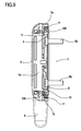
- the handle 1 comprises the above mentioned contact element 7, that can be pre-fitted to the handle body 5 before the handle 1 is mounted on the sash 4.
- the contact element 7 (see in particular Figures 7, 8 and 9 ) has an elongated C shape where there are at least two wide ends or zones 7a, 7b, each having:
- Each wide end or zone 7a, 7b also comprises a wall 12 transversal to the contact element 7, for abutting the base 5a of the handle body 5 when the handle 1 is secured to the sash 4 and located near the hole 100 on the side of the latter opposite the rough surface 11.
- the wall 12 makes it possible to "gauge" the flattening of the inside wall 4b during fastening with the screw 6, preventing excessive deformation at the ends of the slot 2.
- the rough surface 11 has a plurality of grooves 11a with a triangular cross section designed to penetrate the inside surface 4b when the screws 6 are tightened.
- each end 7a, 7b is substantially triangular, with rounded vertex and with the plurality of grooves 11a on both its faces.
- each wide end or zone 7a, 7b is equipped on both sides with respective transversal walls 12.
- a method and handle made in this way achieve the preset aims, thanks to a contact element that can be applied to the handle before the latter is mounted.
Landscapes
- Engineering & Computer Science (AREA)
- Mechanical Engineering (AREA)
- Grates (AREA)
- Manufacture Of Electron Tubes, Discharge Lamp Vessels, Lead-In Wires, And The Like (AREA)
- Lock And Its Accessories (AREA)
Claims (10)
- Verfahren zur Montage eines Griffs (1) für einen Treibstangenverschluss an einer Tür oder einem Fenster, umfassend mindestens einen Durchgangsschlitz (2), der auf einer Oberfläche (3) eines Flügels (4) ausgebildet ist, der einen Teil der Tür/des Fensters einer definierten Dicke (S) bildet; wobei der Griff (1) mindestens Folgendes umfasst:- einen Griffkorpus (5), der mit einer Basis (5a) ausgestattet ist, der am Flügel (4) durch entsprechende Befestiger (6) anbringbar ist, die mit einem Kontaktelement (7) verbindbar sind, und mit einer oberen Fläche (5b), auf der- ein Handgriff (8) montiert ist, der mit- Steuermitteln (9) verbindbar ist, die vom Handgriff (8) angetrieben werden, die von der Basis (5a) des Griffkorpus (5) getragen werden und davon auskragen, wobei die Steuermittel (9) mit Mitteln (10) zum Betätigen der Tür oder des Fensters verbindbar sind, wobei das Verfahren die folgenden Schritte umfasst:- Vormontage des Kontaktelements (7) auf die Basis (5a) des Griffkorpus (5), sodass das Kontaktelement (7) mithilfe eines Befestigers (6) an einem einzigen Punkt der Basis (5a) und bei einem Abstand (D), der größer als die Dicke (S) der Oberfläche (3) ist, verbunden wird;- zuerst Einführen des ungehinderten Bereichs (7a) des Kontaktelements (7) durch den Schlitz (2) und in die rohrförmige Kammer (4a) im Flügel (4);- danach Einführen des behinderten Bereichs (7b) des Kontaktelements (7) durch den Schlitz (2) und in die rohrförmige Kammer (4a);- Verbinden eines zweiten Befestigers (6) mit dem ungehinderten Bereich (7a) des Kontaktelements (7), sodass ein Teil des Bereiches (7a) in Kontakt mit der inneren Oberfläche (4b) des Flügels (4) bewegt wird.
- Verfahren nach Anspruch 1, dadurch gekennzeichnet, dass nach dem Verkuppeln des zweiten Befestigers (6) mit dem ungehinderten Bereich (7a) ein Schritt des endgültigen Befestigens der Bereiche (7a, 7b) des Kontaktelements (7) am Griffkorpus (5) vorhanden ist, sodass der Griff (1) am Flügel (4) an der inneren Oberfläche (4b) der rohrförmigen Kammer (4a) des Flügels (4) verriegelt wird.
- Verfahren nach Anspruch 1, dadurch gekennzeichnet, dass nach dem Schritt des zweiten Einführens ein Schritt des Anschlagens und Positionierens des behinderten Bereichs (7b) des Kontaktelements (7) mithilfe des Befestigers (6) am Ende des Schlitzes (4) vorhanden ist, sodass er der inneren Oberfläche (4b) der rohrförmigen Kammer (4a) zugewandt ist.
- Verfahren nach Anspruch 1, dadurch gekennzeichnet, dass während der Schritte der Aufnahme und der Positionierung der zwei Bereiche (7a, 7b) des Kontaktelements (7) in der rohrförmigen Kammer (4a) das Kontaktelement (7) in einer Position gehalten wird, die im Wesentlichen parallel zum Griffkorpus (5) ist, dank des Kontakts mit den Steuermitteln (9) an einer Seite und an der anderen durch eine Wand (4d), die eine Seite der rohrförmigen Kammer (4a) bildet.
- Verfahren nach Anspruch 1, dadurch gekennzeichnet, dass der erste Schritt des Einführens des ungehinderten Bereichs (7a) des Kontaktelements (7) durch Neigen des Griffkorpus (5) erfolgt.
- Griff für einen Treibstangenverschluss, der an Türen oder Fensters für die Verwendung im Verfahren der Ansprüche 1 bis 5 anbringbar ist, umfassend einen Griffkorpus (5), der mit einer Basis (5a) ausgestattet ist, der an einem Flügel (4) durch entsprechende Befestiger (6) anbringbar ist, die mit einem Kontaktelement (7) verbindbar sind, und mit einer oberen Fläche (5b), auf der ein Handgriff (8) montiert ist, der mit Steuermitteln (9) verbindbar ist, die vom Handgriff (8) angetrieben werden, der von der Basis (5a) des Griffkorpus (5) getragen wird und davon auskragt, wobei die Steuermittel (9) mit Mitteln (10) zum Betätigen der Tür oder des Fensters verbindbar sind, einem Griff für einen Treibstangenverschluss, wobei das Kontaktelement (7) am Griffkorpus (5) vormontiert werden kann, bevor der Griff (1) am Flügel (4) montiert wird; wobei das Kontaktelement (7) mindestens die Form eines länglichen "C"s mit mindestens zwei weiten Enden bzw. Bereichen (7a, 7b) aufweist, die jeweils Folgendes aufweisen:- eine Durchgangsbohrung (100) zum Verkuppeln mit einer entsprechenden Befestigungsschraube (6), die durch eine entsprechende Bohrung (5s) im Griffkorpus (5) verläuft;- mindestens eine nach außen konische, raue Kontaktoberfläche (11), die dazu konzipiert ist, in Kontakt mit der inneren Oberfläche (4b) der rohrförmigen Kammer (4a) zu kommen.
- Griff nach Anspruch 6, dadurch gekennzeichnet, dass jedes weite Ende bzw. jeder weite Bereich ferner eine Wand (12) umfasst, die transversal zum Kontaktelement (7) zum Anschlagen an der Basis (5a) des Griffkorpus (5) ist, wenn der Griff (1) am Flügel (4) angezogen wird und in der Nähe der Bohrung (100) auf der Seite der Letzteren gegenüber der rauen Oberfläche (11) liegt.
- Griff nach Anspruch 6, dadurch gekennzeichnet, dass die raue Oberfläche (11) eine Vielzahl von Nuten (11a) aufweist, aufweisend einen dreieckigen Querschnitt, die dazu konzipiert sind, beim Anziehen in die innere Oberfläche (4b) einzudringen.
- Griff nach Anspruch 8, dadurch gekennzeichnet, dass die raue Oberfläche (11) einen im Wesentlichen dreieckigen Querschnitt aufweist und eine Vielzahl der Nuten (11a) auf ihren beiden Flächen umfasst.
- Griff nach Anspruch 7, dadurch gekennzeichnet, dass jedes der weiten Enden bzw. Bereiche (7a, 7b) an beiden Seiten mit den transversalen Wänden (12) ausgestattet ist.
Applications Claiming Priority (1)
| Application Number | Priority Date | Filing Date | Title |
|---|---|---|---|
| ITBO2009A000209A IT1393486B1 (it) | 2009-03-31 | 2009-03-31 | Metodo per il montaggio di una maniglia a cremonese su un infisso. |
Publications (2)
| Publication Number | Publication Date |
|---|---|
| EP2236706A1 EP2236706A1 (de) | 2010-10-06 |
| EP2236706B1 true EP2236706B1 (de) | 2013-05-15 |
Family
ID=41165531
Family Applications (1)
| Application Number | Title | Priority Date | Filing Date |
|---|---|---|---|
| EP20100156834 Active EP2236706B1 (de) | 2009-03-31 | 2010-03-18 | Verfahren zur Montage eines Griffs für Treibstangenverschluss an einer Tür oder einem Fenster und der Griff selbst |
Country Status (3)
| Country | Link |
|---|---|
| EP (1) | EP2236706B1 (de) |
| ES (1) | ES2423850T3 (de) |
| IT (1) | IT1393486B1 (de) |
Families Citing this family (2)
| Publication number | Priority date | Publication date | Assignee | Title |
|---|---|---|---|---|
| ITPD20110316A1 (it) * | 2011-10-05 | 2013-04-06 | Alutec Srl | Dispositivo a cremonese e procedimento di installazione di un dispositivo a cremonese |
| FR2986028B1 (fr) * | 2012-01-25 | 2015-04-17 | Assa Abloy Aube Anjou | Fixation de ferrure a un vantail ouvrant ou cadre dormant |
Family Cites Families (3)
| Publication number | Priority date | Publication date | Assignee | Title |
|---|---|---|---|---|
| FR2808832A1 (fr) * | 2000-05-10 | 2001-11-16 | Charles Prunet | Ferrure de verrouillage d'ouvrant coulissant a bride rotative quart de tour, procede de montage et ouvrant equipe d'une telle ferrure |
| ITBO20020461A1 (it) * | 2002-07-18 | 2004-01-19 | Gsg Int Spa | Metodo pe rl'appliaczione di maniglie su infissi e maniglia attuante tale metodo |
| FR2877979A1 (fr) * | 2004-11-16 | 2006-05-19 | Charles Prunet | Dispositif de verrouillage pour ouvrant coulissant a tringle(s) de commande et poignee(s) de manoeuvre et procede de montage |
-
2009
- 2009-03-31 IT ITBO2009A000209A patent/IT1393486B1/it active
-
2010
- 2010-03-18 EP EP20100156834 patent/EP2236706B1/de active Active
- 2010-03-18 ES ES10156834T patent/ES2423850T3/es active Active
Also Published As
| Publication number | Publication date |
|---|---|
| IT1393486B1 (it) | 2012-04-27 |
| ES2423850T3 (es) | 2013-09-24 |
| ITBO20090209A1 (it) | 2010-10-01 |
| EP2236706A1 (de) | 2010-10-06 |
Similar Documents
| Publication | Publication Date | Title |
|---|---|---|
| CA2364823C (en) | Casement window with improved tie bar guide and striker | |
| US5159782A (en) | Retainer for pre-hung door | |
| AU2007264393B2 (en) | Improvements in structures and wings | |
| EP3382133B1 (de) | Distanzelement für einen doppelverglasten artikel | |
| EP2072727B1 (de) | Scharnier für eine Metalltür oder für Fenstereinheiten | |
| HK1255947A1 (en) | Spacer element for a double glazed article | |
| US20120286527A1 (en) | Adjustable strike plate | |
| EP2236706B1 (de) | Verfahren zur Montage eines Griffs für Treibstangenverschluss an einer Tür oder einem Fenster und der Griff selbst | |
| EP2093362B1 (de) | Verfahren und Klemmsystem zur Befestigung eines Scharniers oder anderen Beschlags an Profilen für Fenster und Türen | |
| CN111236772B (zh) | 长插销锁 | |
| US6050114A (en) | Latch assembly of padlock for sliding doors | |
| EP2754786B1 (de) | Steuer- und Betätigungseinheit für Schiebetüren oder Schiebefenster | |
| EP3162993B1 (de) | Verschlussmechanismus für ein fenster oder eine tür | |
| KR101682827B1 (ko) | 미닫이문 스토퍼 | |
| KR101674343B1 (ko) | 가변성과 장착성을 개선한 리모델링 창호 | |
| IE53761B1 (en) | Improvements in strikers for locks | |
| US10415266B2 (en) | Door with adjustable lock plate connectors | |
| RU2007109925A (ru) | Шаблон для монтажа комплекта блокирующей фурнитуры и способ монтажа с помощью такого шаблона | |
| WO2009092141A1 (en) | Improvements in structures including wings | |
| GB2503967A (en) | Locking bar having frangible region | |
| AU2009210424A1 (en) | Patch Lock Fitting | |
| CN113982421A (zh) | 复合材料窗的制造方法 | |
| JP7100495B2 (ja) | 上げ落し用の係合構造 | |
| AU2019295415A1 (en) | An electric strike assembly | |
| EP1743996B1 (de) | Betätigungseinheit für Türe oder Fenster |
Legal Events
| Date | Code | Title | Description |
|---|---|---|---|
| PUAI | Public reference made under article 153(3) epc to a published international application that has entered the european phase |
Free format text: ORIGINAL CODE: 0009012 |
|
| AK | Designated contracting states |
Kind code of ref document: A1 Designated state(s): AT BE BG CH CY CZ DE DK EE ES FI FR GB GR HR HU IE IS IT LI LT LU LV MC MK MT NL NO PL PT RO SE SI SK SM TR |
|
| AX | Request for extension of the european patent |
Extension state: AL BA ME RS |
|
| 17P | Request for examination filed |
Effective date: 20100929 |
|
| RIC1 | Information provided on ipc code assigned before grant |
Ipc: E05B 15/02 20060101ALI20121024BHEP Ipc: E05B 9/08 20060101AFI20121024BHEP |
|
| GRAP | Despatch of communication of intention to grant a patent |
Free format text: ORIGINAL CODE: EPIDOSNIGR1 |
|
| GRAS | Grant fee paid |
Free format text: ORIGINAL CODE: EPIDOSNIGR3 |
|
| GRAA | (expected) grant |
Free format text: ORIGINAL CODE: 0009210 |
|
| AK | Designated contracting states |
Kind code of ref document: B1 Designated state(s): AT BE BG CH CY CZ DE DK EE ES FI FR GB GR HR HU IE IS IT LI LT LU LV MC MK MT NL NO PL PT RO SE SI SK SM TR |
|
| REG | Reference to a national code |
Ref country code: GB Ref legal event code: FG4D Ref country code: CH Ref legal event code: EP |
|
| REG | Reference to a national code |
Ref country code: AT Ref legal event code: REF Ref document number: 612240 Country of ref document: AT Kind code of ref document: T Effective date: 20130615 |
|
| REG | Reference to a national code |
Ref country code: IE Ref legal event code: FG4D |
|
| REG | Reference to a national code |
Ref country code: DE Ref legal event code: R096 Ref document number: 602010007033 Country of ref document: DE Effective date: 20130711 |
|
| REG | Reference to a national code |
Ref country code: ES Ref legal event code: FG2A Ref document number: 2423850 Country of ref document: ES Kind code of ref document: T3 Effective date: 20130924 |
|
| REG | Reference to a national code |
Ref country code: AT Ref legal event code: MK05 Ref document number: 612240 Country of ref document: AT Kind code of ref document: T Effective date: 20130515 |
|
| REG | Reference to a national code |
Ref country code: LT Ref legal event code: MG4D |
|
| REG | Reference to a national code |
Ref country code: NL Ref legal event code: VDEP Effective date: 20130515 |
|
| PG25 | Lapsed in a contracting state [announced via postgrant information from national office to epo] |
Ref country code: IS Free format text: LAPSE BECAUSE OF FAILURE TO SUBMIT A TRANSLATION OF THE DESCRIPTION OR TO PAY THE FEE WITHIN THE PRESCRIBED TIME-LIMIT Effective date: 20130915 Ref country code: NO Free format text: LAPSE BECAUSE OF FAILURE TO SUBMIT A TRANSLATION OF THE DESCRIPTION OR TO PAY THE FEE WITHIN THE PRESCRIBED TIME-LIMIT Effective date: 20130815 Ref country code: LT Free format text: LAPSE BECAUSE OF FAILURE TO SUBMIT A TRANSLATION OF THE DESCRIPTION OR TO PAY THE FEE WITHIN THE PRESCRIBED TIME-LIMIT Effective date: 20130515 Ref country code: FI Free format text: LAPSE BECAUSE OF FAILURE TO SUBMIT A TRANSLATION OF THE DESCRIPTION OR TO PAY THE FEE WITHIN THE PRESCRIBED TIME-LIMIT Effective date: 20130515 Ref country code: SE Free format text: LAPSE BECAUSE OF FAILURE TO SUBMIT A TRANSLATION OF THE DESCRIPTION OR TO PAY THE FEE WITHIN THE PRESCRIBED TIME-LIMIT Effective date: 20130515 Ref country code: SI Free format text: LAPSE BECAUSE OF FAILURE TO SUBMIT A TRANSLATION OF THE DESCRIPTION OR TO PAY THE FEE WITHIN THE PRESCRIBED TIME-LIMIT Effective date: 20130515 Ref country code: GR Free format text: LAPSE BECAUSE OF FAILURE TO SUBMIT A TRANSLATION OF THE DESCRIPTION OR TO PAY THE FEE WITHIN THE PRESCRIBED TIME-LIMIT Effective date: 20130816 Ref country code: PT Free format text: LAPSE BECAUSE OF FAILURE TO SUBMIT A TRANSLATION OF THE DESCRIPTION OR TO PAY THE FEE WITHIN THE PRESCRIBED TIME-LIMIT Effective date: 20130916 Ref country code: AT Free format text: LAPSE BECAUSE OF FAILURE TO SUBMIT A TRANSLATION OF THE DESCRIPTION OR TO PAY THE FEE WITHIN THE PRESCRIBED TIME-LIMIT Effective date: 20130515 |
|
| PG25 | Lapsed in a contracting state [announced via postgrant information from national office to epo] |
Ref country code: BG Free format text: LAPSE BECAUSE OF FAILURE TO SUBMIT A TRANSLATION OF THE DESCRIPTION OR TO PAY THE FEE WITHIN THE PRESCRIBED TIME-LIMIT Effective date: 20130815 Ref country code: HR Free format text: LAPSE BECAUSE OF FAILURE TO SUBMIT A TRANSLATION OF THE DESCRIPTION OR TO PAY THE FEE WITHIN THE PRESCRIBED TIME-LIMIT Effective date: 20130515 Ref country code: PL Free format text: LAPSE BECAUSE OF FAILURE TO SUBMIT A TRANSLATION OF THE DESCRIPTION OR TO PAY THE FEE WITHIN THE PRESCRIBED TIME-LIMIT Effective date: 20130515 |
|
| PG25 | Lapsed in a contracting state [announced via postgrant information from national office to epo] |
Ref country code: LV Free format text: LAPSE BECAUSE OF FAILURE TO SUBMIT A TRANSLATION OF THE DESCRIPTION OR TO PAY THE FEE WITHIN THE PRESCRIBED TIME-LIMIT Effective date: 20130515 |
|
| PG25 | Lapsed in a contracting state [announced via postgrant information from national office to epo] |
Ref country code: DK Free format text: LAPSE BECAUSE OF FAILURE TO SUBMIT A TRANSLATION OF THE DESCRIPTION OR TO PAY THE FEE WITHIN THE PRESCRIBED TIME-LIMIT Effective date: 20130515 Ref country code: SK Free format text: LAPSE BECAUSE OF FAILURE TO SUBMIT A TRANSLATION OF THE DESCRIPTION OR TO PAY THE FEE WITHIN THE PRESCRIBED TIME-LIMIT Effective date: 20130515 Ref country code: CZ Free format text: LAPSE BECAUSE OF FAILURE TO SUBMIT A TRANSLATION OF THE DESCRIPTION OR TO PAY THE FEE WITHIN THE PRESCRIBED TIME-LIMIT Effective date: 20130515 Ref country code: BE Free format text: LAPSE BECAUSE OF FAILURE TO SUBMIT A TRANSLATION OF THE DESCRIPTION OR TO PAY THE FEE WITHIN THE PRESCRIBED TIME-LIMIT Effective date: 20130515 Ref country code: EE Free format text: LAPSE BECAUSE OF FAILURE TO SUBMIT A TRANSLATION OF THE DESCRIPTION OR TO PAY THE FEE WITHIN THE PRESCRIBED TIME-LIMIT Effective date: 20130515 |
|
| PG25 | Lapsed in a contracting state [announced via postgrant information from national office to epo] |
Ref country code: RO Free format text: LAPSE BECAUSE OF FAILURE TO SUBMIT A TRANSLATION OF THE DESCRIPTION OR TO PAY THE FEE WITHIN THE PRESCRIBED TIME-LIMIT Effective date: 20130515 Ref country code: NL Free format text: LAPSE BECAUSE OF FAILURE TO SUBMIT A TRANSLATION OF THE DESCRIPTION OR TO PAY THE FEE WITHIN THE PRESCRIBED TIME-LIMIT Effective date: 20130515 |
|
| PLBE | No opposition filed within time limit |
Free format text: ORIGINAL CODE: 0009261 |
|
| STAA | Information on the status of an ep patent application or granted ep patent |
Free format text: STATUS: NO OPPOSITION FILED WITHIN TIME LIMIT |
|
| 26N | No opposition filed |
Effective date: 20140218 |
|
| REG | Reference to a national code |
Ref country code: DE Ref legal event code: R097 Ref document number: 602010007033 Country of ref document: DE Effective date: 20140218 |
|
| PG25 | Lapsed in a contracting state [announced via postgrant information from national office to epo] |
Ref country code: LU Free format text: LAPSE BECAUSE OF FAILURE TO SUBMIT A TRANSLATION OF THE DESCRIPTION OR TO PAY THE FEE WITHIN THE PRESCRIBED TIME-LIMIT Effective date: 20140318 |
|
| REG | Reference to a national code |
Ref country code: CH Ref legal event code: PL |
|
| GBPC | Gb: european patent ceased through non-payment of renewal fee |
Effective date: 20140318 |
|
| REG | Reference to a national code |
Ref country code: FR Ref legal event code: ST Effective date: 20141128 |
|
| REG | Reference to a national code |
Ref country code: IE Ref legal event code: MM4A |
|
| PG25 | Lapsed in a contracting state [announced via postgrant information from national office to epo] |
Ref country code: LI Free format text: LAPSE BECAUSE OF NON-PAYMENT OF DUE FEES Effective date: 20140331 Ref country code: CH Free format text: LAPSE BECAUSE OF NON-PAYMENT OF DUE FEES Effective date: 20140331 Ref country code: GB Free format text: LAPSE BECAUSE OF NON-PAYMENT OF DUE FEES Effective date: 20140318 Ref country code: IE Free format text: LAPSE BECAUSE OF NON-PAYMENT OF DUE FEES Effective date: 20140318 Ref country code: FR Free format text: LAPSE BECAUSE OF NON-PAYMENT OF DUE FEES Effective date: 20140331 |
|
| PG25 | Lapsed in a contracting state [announced via postgrant information from national office to epo] |
Ref country code: MT Free format text: LAPSE BECAUSE OF FAILURE TO SUBMIT A TRANSLATION OF THE DESCRIPTION OR TO PAY THE FEE WITHIN THE PRESCRIBED TIME-LIMIT Effective date: 20130515 |
|
| PG25 | Lapsed in a contracting state [announced via postgrant information from national office to epo] |
Ref country code: SM Free format text: LAPSE BECAUSE OF FAILURE TO SUBMIT A TRANSLATION OF THE DESCRIPTION OR TO PAY THE FEE WITHIN THE PRESCRIBED TIME-LIMIT Effective date: 20130515 |
|
| PG25 | Lapsed in a contracting state [announced via postgrant information from national office to epo] |
Ref country code: MC Free format text: LAPSE BECAUSE OF FAILURE TO SUBMIT A TRANSLATION OF THE DESCRIPTION OR TO PAY THE FEE WITHIN THE PRESCRIBED TIME-LIMIT Effective date: 20130515 |
|
| PG25 | Lapsed in a contracting state [announced via postgrant information from national office to epo] |
Ref country code: CY Free format text: LAPSE BECAUSE OF FAILURE TO SUBMIT A TRANSLATION OF THE DESCRIPTION OR TO PAY THE FEE WITHIN THE PRESCRIBED TIME-LIMIT Effective date: 20130515 |
|
| PG25 | Lapsed in a contracting state [announced via postgrant information from national office to epo] |
Ref country code: TR Free format text: LAPSE BECAUSE OF FAILURE TO SUBMIT A TRANSLATION OF THE DESCRIPTION OR TO PAY THE FEE WITHIN THE PRESCRIBED TIME-LIMIT Effective date: 20130515 Ref country code: HU Free format text: LAPSE BECAUSE OF FAILURE TO SUBMIT A TRANSLATION OF THE DESCRIPTION OR TO PAY THE FEE WITHIN THE PRESCRIBED TIME-LIMIT; INVALID AB INITIO Effective date: 20100318 |
|
| PG25 | Lapsed in a contracting state [announced via postgrant information from national office to epo] |
Ref country code: MK Free format text: LAPSE BECAUSE OF FAILURE TO SUBMIT A TRANSLATION OF THE DESCRIPTION OR TO PAY THE FEE WITHIN THE PRESCRIBED TIME-LIMIT Effective date: 20130515 |
|
| P01 | Opt-out of the competence of the unified patent court (upc) registered |
Effective date: 20230506 |
|
| PGFP | Annual fee paid to national office [announced via postgrant information from national office to epo] |
Ref country code: ES Payment date: 20250415 Year of fee payment: 16 |
|
| PGFP | Annual fee paid to national office [announced via postgrant information from national office to epo] |
Ref country code: DE Payment date: 20260320 Year of fee payment: 17 |
|
| PGFP | Annual fee paid to national office [announced via postgrant information from national office to epo] |
Ref country code: IT Payment date: 20260319 Year of fee payment: 17 |