EP2236738A2 - Verfahren und Vorrichtung zur Isolierung und Behandlung von diskreten Bereichen in einem Bohrloch - Google Patents
Verfahren und Vorrichtung zur Isolierung und Behandlung von diskreten Bereichen in einem Bohrloch Download PDFInfo
- Publication number
- EP2236738A2 EP2236738A2 EP10157828A EP10157828A EP2236738A2 EP 2236738 A2 EP2236738 A2 EP 2236738A2 EP 10157828 A EP10157828 A EP 10157828A EP 10157828 A EP10157828 A EP 10157828A EP 2236738 A2 EP2236738 A2 EP 2236738A2
- Authority
- EP
- European Patent Office
- Prior art keywords
- assembly
- packer
- wellbore
- unloader
- inner mandrel
- Prior art date
- Legal status (The legal status is an assumption and is not a legal conclusion. Google has not performed a legal analysis and makes no representation as to the accuracy of the status listed.)
- Granted
Links
Images


Classifications
-
- E—FIXED CONSTRUCTIONS
- E21—EARTH OR ROCK DRILLING; MINING
- E21B—EARTH OR ROCK DRILLING; OBTAINING OIL, GAS, WATER, SOLUBLE OR MELTABLE MATERIALS OR A SLURRY OF MINERALS FROM WELLS
- E21B43/00—Methods or apparatus for obtaining oil, gas, water, soluble or meltable materials or a slurry of minerals from wells
- E21B43/25—Methods for stimulating production
- E21B43/26—Methods for stimulating production by forming crevices or fractures
-
- E—FIXED CONSTRUCTIONS
- E21—EARTH OR ROCK DRILLING; MINING
- E21B—EARTH OR ROCK DRILLING; OBTAINING OIL, GAS, WATER, SOLUBLE OR MELTABLE MATERIALS OR A SLURRY OF MINERALS FROM WELLS
- E21B23/00—Apparatus for displacing, setting, locking, releasing or removing tools, packers or the like in boreholes or wells
- E21B23/01—Apparatus for displacing, setting, locking, releasing or removing tools, packers or the like in boreholes or wells for anchoring the tools or the like
-
- E—FIXED CONSTRUCTIONS
- E21—EARTH OR ROCK DRILLING; MINING
- E21B—EARTH OR ROCK DRILLING; OBTAINING OIL, GAS, WATER, SOLUBLE OR MELTABLE MATERIALS OR A SLURRY OF MINERALS FROM WELLS
- E21B33/00—Sealing or packing boreholes or wells
- E21B33/10—Sealing or packing boreholes or wells in the borehole
- E21B33/12—Packers; Plugs
- E21B33/124—Units with longitudinally-spaced plugs for isolating the intermediate space
-
- E—FIXED CONSTRUCTIONS
- E21—EARTH OR ROCK DRILLING; MINING
- E21B—EARTH OR ROCK DRILLING; OBTAINING OIL, GAS, WATER, SOLUBLE OR MELTABLE MATERIALS OR A SLURRY OF MINERALS FROM WELLS
- E21B43/00—Methods or apparatus for obtaining oil, gas, water, soluble or meltable materials or a slurry of minerals from wells
- E21B43/12—Methods or apparatus for controlling the flow of the obtained fluid to or in wells
- E21B43/121—Lifting well fluids
Definitions
- Figure 3B illustrates a cross sectional view of the packer in a set position according to one embodiment of the invention.
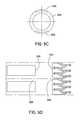
- Figure 5C illustrates a top cross sectional view of the inner mandrel of the anchor according to one embodiment of the invention.
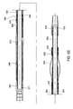
- Figure 8A illustrates a cross sectional view of a packer in an unset position according to one embodiment of the invention.
- the tension in the tubing string 110 and the assembly 100 is released, which may be facilitated by pushing on the tubing string 110.
- the tension release allows the unloader 200 to actuate into an open position to permit fluid communication between the unloader 200 and the annulus surrounding the assembly 100 to equalize the pressure above and below the packer 300A to help unsetting of the packer 300A.
- the tension release also allows the packers 300A and 300B and the anchor 500 to unset from engagement with the wellbore.
- the assembly 100 may then be removed from the wellbore. Alternatively, the assembly 100 may be relocated to another area of interest in the formation to conduct another fracturing operation.
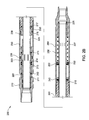
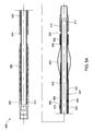
- a wiper ring 221 may be used at the lower end of the inner mandrel 220 between the inner mandrel 220/lower housing 260 interface to prevent and remove debris that flows through the unloader 200.
- the lower end of the lower housing 260 may be configured to threadedly connect to the packer 300A or other downhole tool of the assembly 100.
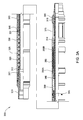
- the biasing member 325 may include a spring that abuts a shoulder formed on the outer diameter of the upper end of the inner mandrel 320 at one end and abuts the upper end of a retainer 335 at the other end, thereby biasing the inner mandrel 320 against the bottom end of the top sub 310.
- the biasing member 325 may be used to facilitate unsetting of the packing element 360.
- the retainer 335 includes a cylindrical body having a bore disposed through the body, through which the inner mandrel 320 is provided. The retainer 335 is surrounded by and coupled to the upper housing 330 by a set screw 331.
- the member 345 may include a recess on its outer diameter for receiving a set screw disposed through the body of the lower housing 350 to axially fix the lower housing 350 relative to the inner mandrel 320.
- the lower housing 350 includes a cylindrical body having a bore disposed through the body, through which the inner mandrel 320 is provided. Also, the lower end of the lower housing 350 surrounds a portion of the spring mandrel 340 such that a shoulder formed on the inner diameter of the lower housing 350 abuts a shoulder formed on the outer diameter of the spring mandrel 340.
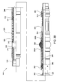
- the second retainer 545 includes a cylindrical body having a bore disposed through the body, through which the inner mandrel 520 is provided.
- the second retainer 545 includes raised portions on its outer diameter for engaging openings disposed through the lower end of the members 541.
- the outer sleeve 560 may be coupled around the second retainer 545 to prevent disengagement of the raised portions on the outer diameter of the second retainer 545 and the openings in the lower end of the members 541.
- the lower end of the outer sleeve 560 may include a shoulder disposed on its inner diameter that engages a shoulder disposed on the outer diameter of the inner mandrel 520 to limit the axial movement between the two components. Coupled to the lower end of the outer diameter of the outer sleeve 560 is the slip 570.
- the slip 570 may be coupled to the outer sleeve 560 via a threaded insert 575 that is partially disposed in the body of the outer sleeve 560.
- the slip 570 may include a plurality of slip members, such as collets, radially disposed around the slip 570 having teeth disposed on the outer periphery of the ends of the slip members to engage and secure the anchor 500 in the wellbore.
- the cone 580 includes a cylindrical body having a bore disposed through the body, through which the inner mandrel 520 is provided.
- the cone 580 has a tapered nose operable to engage the tapered inner surface of the slip 570.
- the cone 580 is axially fixed relative to the inner mandrel 520 and abuts the upper end of the bottom sub 590.
- the bottom sub 590 includes a cylindrical body having a bore disposed through the body, through which the inner mandrel 520 is partially provided.
- the upper end of the bottom sub 590 is coupled to the lower end of the inner mandrel 520.
- a seal 512 such as an o-ring, may be provided between the bottom sub 590/inner mandrel 520 interface.
- the lower end of the bottom sub 590 may be configured to connect to a variety of other downhole tools that may be included or attached to the assembly 100.
- the relative movement between the inner mandrel 520 (and thus the cone 580) and the outer sleeve 560 (and thus the slip 570) is controlled with a pair of lugs 555 and a pair of pins 557 that are disposed through the inner sleeve 550 and facilitated with the friction section 540.
- the friction section 540 creates a friction interface with the wellbore to allow the inner mandrel 520 to move axially relative to the outer sleeve 560 as the assembly 100 is raised and lowered.
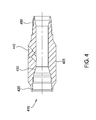
- the outer sleeve 660 may include a cylindrical body having a bore therethrough, which surrounds the inner mandrel 620 and an inner sleeve 665.
- the lower end of the outer sleeve 660 is coupled to the slip 670.
- the slip 570 may be coupled to the outer sleeve 660 via a threaded insert 675 that is partially disposed in the body of the outer sleeve 660.
- the packer 800 includes a top sub 810, an inner mandrel 820, an upper housing 830, a coupling member 837, a spring mandrel 840, a sleeve 850, a lower housing 853, a packing element 860, a latch sub 870, and a bottom sub 880.
- the top sub 810 includes a cylindrical body having a bore disposed through the body. The inner diameter of the upper end of the top sub 810 may be configured to connect to the injection port 400, a tubular, or other downhole tool in the assembly 100.
- the lower end of the top sub 810 is coupled to the upper end of the upper housing 830.
- the top sub 810 and the upper housing 830 interface may be secured together using, for example, a set screw.
- the top sub 810 and the upper housing 830 interface may also include a seal 811, such as an o-ring.
- a coupling member 837 connects the lower end of the upper housing 830 to the upper end of the sleeve 850, such as through a threaded engagement.
- the coupling member 837 includes a cylindrical body having a bore disposed through the body, in which the inner mandrel 820 is provided.
- the sleeve 850 also includes a cylindrical body having a bore disposed through the body, in which the inner mandrel 820 as well as the spring mandrel 840 is provided.
- the spring mandrel 840 includes a cylindrical body having a bore disposed through the body and is located between the sleeve 850 and the inner mandrel 820. The upper end of the spring mandrel 840 may engage the coupling member 837.
- the inner mandrel 820 may include a cylindrical body having a bore disposed through only the lower end of the body.
- the upper end of the inner mandrel 820 may include a solid tubular member to prevent fluid communication between the upper end and the lower end of the inner mandrel 820.
- this embodiment of the packer 800 may be used in place of the packer 300B described above.
- an open port may be located below the packer 800 to allow the pressure from the annulus above the packer 800 to be directed to the annulus below the packer 800 to allow the pressure across the packer 800 to be equalized when necessary.
- an anchor as described above, having an open throughbore in communication with the wellbore may be located below the packer 800.
- the bottom sub 880 includes a cylindrical body having a bore disposed through the body and is coupled to the lower end of the inner mandrel 820.
- the bottom sub 880 and the inner mandrel 820 interface may be secured together using, for example, a set screw.
- the bottom sub 880 and the inner mandrel 820 interface may also include a seal 813, such as an o-ring.
- a recessed portion on the outer diameter of the bottom sub 880 is adapted for receiving the latching fingers of the latch sub 870 to prevent premature actuation of the packing element 860.
- the lower end of the bottom sub 880 may be configured to be coupled to the spacer pipe 130, the anchor 500, or other downhole tool that may be included in the assembly 100.
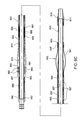
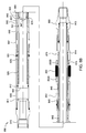
- FIG. 8B illustrates the packer 800 in a set position according to one embodiment of the invention.
- the top sub 810, the upper housing 830, the retainer 835, the coupling member 837, the sleeve 850, the spring mandrel 840, and the latch sub 870 are axially movable relative to the inner mandrel 820, the lower housing 853, and the bottom sub 880.
- the top sub 810 is separated from the inner mandrel 820, thereby compressing the biasing member 825 between the shoulder on the inner mandrel 820 and the retainer 835.
- the latching fingers of the latch sub 870 disengage from the bottom sub 880 to allow actuation of the packing element 860.
- the latch sub 870 and thus the lower gage 855B is axially moved toward the stationary lower housing 853 and the upper gage 855A to actuate the packing element 860 disposed therebetween.
- the lower housing 853 is axially fixed by the anchor 500 via the member 845, inner mandrel 820, and bottom sub 880.
- the packing element 860 is actuated into sealing engagement with the surrounding surface, which may be the wellbore for example.
Landscapes
- Life Sciences & Earth Sciences (AREA)
- Engineering & Computer Science (AREA)
- Geology (AREA)
- Mining & Mineral Resources (AREA)
- Physics & Mathematics (AREA)
- Environmental & Geological Engineering (AREA)
- Fluid Mechanics (AREA)
- General Life Sciences & Earth Sciences (AREA)
- Geochemistry & Mineralogy (AREA)
- Consolidation Of Soil By Introduction Of Solidifying Substances Into Soil (AREA)
Applications Claiming Priority (1)
| Application Number | Priority Date | Filing Date | Title |
|---|---|---|---|
| US12/411,338 US9291044B2 (en) | 2009-03-25 | 2009-03-25 | Method and apparatus for isolating and treating discrete zones within a wellbore |
Publications (3)
| Publication Number | Publication Date |
|---|---|
| EP2236738A2 true EP2236738A2 (de) | 2010-10-06 |
| EP2236738A3 EP2236738A3 (de) | 2012-11-21 |
| EP2236738B1 EP2236738B1 (de) | 2016-08-03 |
Family
ID=42197651
Family Applications (1)
| Application Number | Title | Priority Date | Filing Date |
|---|---|---|---|
| EP10157828.4A Active EP2236738B1 (de) | 2009-03-25 | 2010-03-25 | Verfahren und Vorrichtung zur Isolierung und Behandlung von diskreten Bereichen in einem Bohrloch |
Country Status (4)
| Country | Link |
|---|---|
| US (1) | US9291044B2 (de) |
| EP (1) | EP2236738B1 (de) |
| AU (1) | AU2010201173B2 (de) |
| CA (1) | CA2697394C (de) |
Cited By (2)
| Publication number | Priority date | Publication date | Assignee | Title |
|---|---|---|---|---|
| CN102733790A (zh) * | 2011-04-15 | 2012-10-17 | 盐城市佳鑫石化机械制造有限公司 | 带水力锚的滑套喷砂器 |
| WO2014158028A1 (en) * | 2013-03-27 | 2014-10-02 | Target Intervention As | Downhole tool device and method for using the same |
Families Citing this family (68)
| Publication number | Priority date | Publication date | Assignee | Title |
|---|---|---|---|---|
| US9079246B2 (en) * | 2009-12-08 | 2015-07-14 | Baker Hughes Incorporated | Method of making a nanomatrix powder metal compact |
| US8327931B2 (en) | 2009-12-08 | 2012-12-11 | Baker Hughes Incorporated | Multi-component disappearing tripping ball and method for making the same |
| US9101978B2 (en) | 2002-12-08 | 2015-08-11 | Baker Hughes Incorporated | Nanomatrix powder metal compact |
| US9109429B2 (en) | 2002-12-08 | 2015-08-18 | Baker Hughes Incorporated | Engineered powder compact composite material |
| US8403037B2 (en) | 2009-12-08 | 2013-03-26 | Baker Hughes Incorporated | Dissolvable tool and method |
| US9682425B2 (en) | 2009-12-08 | 2017-06-20 | Baker Hughes Incorporated | Coated metallic powder and method of making the same |
| DE602008006176D1 (de) * | 2008-05-30 | 2011-05-26 | Schlumberger Technology Bv | Injektionsvorrichtung und -verfahren |
| US8186446B2 (en) * | 2009-03-25 | 2012-05-29 | Weatherford/Lamb, Inc. | Method and apparatus for a packer assembly |
| US9291044B2 (en) | 2009-03-25 | 2016-03-22 | Weatherford Technology Holdings, Llc | Method and apparatus for isolating and treating discrete zones within a wellbore |
| CA2891734C (en) | 2009-11-06 | 2017-08-22 | Weatherford Technology Holdings, Llc | Method and apparatus for a wellbore accumulator system assembly |
| US9243475B2 (en) | 2009-12-08 | 2016-01-26 | Baker Hughes Incorporated | Extruded powder metal compact |
| US10240419B2 (en) | 2009-12-08 | 2019-03-26 | Baker Hughes, A Ge Company, Llc | Downhole flow inhibition tool and method of unplugging a seat |
| US9227243B2 (en) | 2009-12-08 | 2016-01-05 | Baker Hughes Incorporated | Method of making a powder metal compact |
| US9127515B2 (en) | 2010-10-27 | 2015-09-08 | Baker Hughes Incorporated | Nanomatrix carbon composite |
| US8573295B2 (en) | 2010-11-16 | 2013-11-05 | Baker Hughes Incorporated | Plug and method of unplugging a seat |
| US8425651B2 (en) | 2010-07-30 | 2013-04-23 | Baker Hughes Incorporated | Nanomatrix metal composite |
| US8528633B2 (en) | 2009-12-08 | 2013-09-10 | Baker Hughes Incorporated | Dissolvable tool and method |
| US8424610B2 (en) | 2010-03-05 | 2013-04-23 | Baker Hughes Incorporated | Flow control arrangement and method |
| US8776884B2 (en) | 2010-08-09 | 2014-07-15 | Baker Hughes Incorporated | Formation treatment system and method |
| CA2992766C (en) | 2010-10-15 | 2020-11-03 | Weatherford Technology Holdings, Llc | Method and apparatus for isolating and treating discrete zones within a wellbore |
| US9090955B2 (en) | 2010-10-27 | 2015-07-28 | Baker Hughes Incorporated | Nanomatrix powder metal composite |
| US9080098B2 (en) | 2011-04-28 | 2015-07-14 | Baker Hughes Incorporated | Functionally gradient composite article |
| US8631876B2 (en) | 2011-04-28 | 2014-01-21 | Baker Hughes Incorporated | Method of making and using a functionally gradient composite tool |
| US9139928B2 (en) | 2011-06-17 | 2015-09-22 | Baker Hughes Incorporated | Corrodible downhole article and method of removing the article from downhole environment |
| US8875799B2 (en) * | 2011-07-08 | 2014-11-04 | Halliburton Energy Services, Inc. | Covered retaining shoe configurations for use in a downhole tool |
| US9707739B2 (en) | 2011-07-22 | 2017-07-18 | Baker Hughes Incorporated | Intermetallic metallic composite, method of manufacture thereof and articles comprising the same |
| US8783365B2 (en) | 2011-07-28 | 2014-07-22 | Baker Hughes Incorporated | Selective hydraulic fracturing tool and method thereof |
| US9643250B2 (en) | 2011-07-29 | 2017-05-09 | Baker Hughes Incorporated | Method of controlling the corrosion rate of alloy particles, alloy particle with controlled corrosion rate, and articles comprising the particle |
| US9833838B2 (en) | 2011-07-29 | 2017-12-05 | Baker Hughes, A Ge Company, Llc | Method of controlling the corrosion rate of alloy particles, alloy particle with controlled corrosion rate, and articles comprising the particle |
| US9057242B2 (en) | 2011-08-05 | 2015-06-16 | Baker Hughes Incorporated | Method of controlling corrosion rate in downhole article, and downhole article having controlled corrosion rate |
| US9033055B2 (en) | 2011-08-17 | 2015-05-19 | Baker Hughes Incorporated | Selectively degradable passage restriction and method |
| US9856547B2 (en) | 2011-08-30 | 2018-01-02 | Bakers Hughes, A Ge Company, Llc | Nanostructured powder metal compact |
| US9090956B2 (en) | 2011-08-30 | 2015-07-28 | Baker Hughes Incorporated | Aluminum alloy powder metal compact |
| US9109269B2 (en) | 2011-08-30 | 2015-08-18 | Baker Hughes Incorporated | Magnesium alloy powder metal compact |
| US9643144B2 (en) | 2011-09-02 | 2017-05-09 | Baker Hughes Incorporated | Method to generate and disperse nanostructures in a composite material |
| US9187990B2 (en) | 2011-09-03 | 2015-11-17 | Baker Hughes Incorporated | Method of using a degradable shaped charge and perforating gun system |
| US9347119B2 (en) | 2011-09-03 | 2016-05-24 | Baker Hughes Incorporated | Degradable high shock impedance material |
| US9133695B2 (en) | 2011-09-03 | 2015-09-15 | Baker Hughes Incorporated | Degradable shaped charge and perforating gun system |
| US9284812B2 (en) | 2011-11-21 | 2016-03-15 | Baker Hughes Incorporated | System for increasing swelling efficiency |
| US9010416B2 (en) | 2012-01-25 | 2015-04-21 | Baker Hughes Incorporated | Tubular anchoring system and a seat for use in the same |
| US9068428B2 (en) | 2012-02-13 | 2015-06-30 | Baker Hughes Incorporated | Selectively corrodible downhole article and method of use |
| US9605508B2 (en) | 2012-05-08 | 2017-03-28 | Baker Hughes Incorporated | Disintegrable and conformable metallic seal, and method of making the same |
| CN102839920B (zh) * | 2012-08-07 | 2015-04-22 | 中国石油化工股份有限公司 | 一种水平井多段改造管柱及使用方法 |
| WO2014130053A1 (en) * | 2013-02-25 | 2014-08-28 | Halliburton Energy Services, Inc. | Autofill and circulation assembly and method of using the same |
| US10422202B2 (en) | 2013-06-28 | 2019-09-24 | Innovex Downhole Solutions, Inc. | Linearly indexing wellbore valve |
| US9896908B2 (en) | 2013-06-28 | 2018-02-20 | Team Oil Tools, Lp | Well bore stimulation valve |
| CA2820704C (en) * | 2013-07-10 | 2018-10-16 | Don Getzlaf | Fracturing valve |
| US9816339B2 (en) | 2013-09-03 | 2017-11-14 | Baker Hughes, A Ge Company, Llc | Plug reception assembly and method of reducing restriction in a borehole |
| US11167343B2 (en) | 2014-02-21 | 2021-11-09 | Terves, Llc | Galvanically-active in situ formed particles for controlled rate dissolving tools |
| US10689740B2 (en) | 2014-04-18 | 2020-06-23 | Terves, LLCq | Galvanically-active in situ formed particles for controlled rate dissolving tools |
| WO2015127174A1 (en) | 2014-02-21 | 2015-08-27 | Terves, Inc. | Fluid activated disintegrating metal system |
| US10138704B2 (en) | 2014-06-27 | 2018-11-27 | Weatherford Technology Holdings, Llc | Straddle packer system |
| US9910026B2 (en) | 2015-01-21 | 2018-03-06 | Baker Hughes, A Ge Company, Llc | High temperature tracers for downhole detection of produced water |
| US10378303B2 (en) | 2015-03-05 | 2019-08-13 | Baker Hughes, A Ge Company, Llc | Downhole tool and method of forming the same |
| US10221637B2 (en) | 2015-08-11 | 2019-03-05 | Baker Hughes, A Ge Company, Llc | Methods of manufacturing dissolvable tools via liquid-solid state molding |
| US10016810B2 (en) | 2015-12-14 | 2018-07-10 | Baker Hughes, A Ge Company, Llc | Methods of manufacturing degradable tools using a galvanic carrier and tools manufactured thereof |
| CA3012511A1 (en) | 2017-07-27 | 2019-01-27 | Terves Inc. | Degradable metal matrix composite |
| US10900319B2 (en) | 2017-12-14 | 2021-01-26 | Exacta-Frac Energy Services, Inc. | Cased bore straddle packer |
| CN108757000B (zh) * | 2018-04-12 | 2019-09-24 | 山东科技大学 | 一种基于钻机动力的井下快速割缝定向水力压裂系统及方法 |
| US10900320B2 (en) | 2019-03-01 | 2021-01-26 | Exacta-Frac Energy Services, Inc | Uphole end for a compression-set straddle packer |
| US11035189B2 (en) | 2019-04-01 | 2021-06-15 | Exacta-Frac Energy Services, Inc. | Compression-set straddle packer with fluid pressure-boosted packer set |
| CN110513074B (zh) * | 2019-08-16 | 2021-11-30 | 中国石油天然气集团有限公司 | 可溶解桥塞 |
| US11168537B2 (en) | 2020-04-06 | 2021-11-09 | Exacta-Frac Energy Services, Inc. | Fluid-pressure-set uphole end for a hybrid straddle packer |
| US11555364B2 (en) | 2020-10-30 | 2023-01-17 | Weatherford Technology Holdings, Llc | High expansion anchoring system |
| US11713643B2 (en) | 2020-10-30 | 2023-08-01 | Weatherford Technology Holdings, Llc | Controlled deformation and shape recovery of packing elements |
| US11959352B2 (en) | 2020-10-30 | 2024-04-16 | Weatherford Technology Holdings, Llc | Retrievable high expansion bridge plug and packer with retractable anti-extrusion backup system |
| US11686174B2 (en) | 2021-06-10 | 2023-06-27 | Frank's International, Llc | Storm packer anchor and setting tool |
| CN119712027B (zh) * | 2023-09-26 | 2026-04-10 | 中国石油天然气股份有限公司 | 定液量举升装置及定液量举升方法 |
Family Cites Families (26)
| Publication number | Priority date | Publication date | Assignee | Title |
|---|---|---|---|---|
| US3024846A (en) * | 1957-11-15 | 1962-03-13 | Lonnie L Gage | Dual completion packer tool |
| US3096823A (en) * | 1959-04-28 | 1963-07-09 | Baker Oil Tools Inc | Well bore testing and pressuring apparatus |
| US3526278A (en) * | 1968-04-16 | 1970-09-01 | Byron Jackson Inc | High volume main valve for formation testers |
| US4485876A (en) * | 1983-09-26 | 1984-12-04 | Baker Oil Tools, Inc. | Valving apparatus for downhole tools |
| US4605062A (en) * | 1985-06-10 | 1986-08-12 | Baker Oil Tools, Inc. | Subsurface injection tool |
| US4856583A (en) * | 1987-11-20 | 1989-08-15 | Dresser Industries, Inc. | Apparatus for treating well bores |
| US5782306A (en) * | 1995-12-14 | 1998-07-21 | Site Oil Tools, Inc. | Open hole straddle system |
| US6257339B1 (en) * | 1999-10-02 | 2001-07-10 | Weatherford/Lamb, Inc | Packer system |
| US7114558B2 (en) * | 1999-11-06 | 2006-10-03 | Weatherford/Lamb, Inc. | Filtered actuator port for hydraulically actuated downhole tools |
| US6695057B2 (en) * | 2001-05-15 | 2004-02-24 | Weatherford/Lamb, Inc. | Fracturing port collar for wellbore pack-off system, and method for using same |
| US6253856B1 (en) * | 1999-11-06 | 2001-07-03 | Weatherford/Lamb, Inc. | Pack-off system |
| US6883610B2 (en) * | 2000-12-20 | 2005-04-26 | Karol Depiak | Straddle packer systems |
| US6655461B2 (en) * | 2001-04-18 | 2003-12-02 | Schlumberger Technology Corporation | Straddle packer tool and method for well treating having valving and fluid bypass system |
| CA2392277C (en) * | 2001-06-29 | 2008-02-12 | Bj Services Company Canada | Bottom hole assembly |
| CA2365218A1 (en) * | 2001-12-14 | 2003-06-14 | Vitold P. Serafin | Open hole straddle tool |
| US6823945B2 (en) | 2002-09-23 | 2004-11-30 | Schlumberger Technology Corp. | Pressure compensating apparatus and method for downhole tools |
| US7011157B2 (en) * | 2002-10-31 | 2006-03-14 | Schlumberger Technology Corporation | Method and apparatus for cleaning a fractured interval between two packers |
| US7051812B2 (en) * | 2003-02-19 | 2006-05-30 | Schlumberger Technology Corp. | Fracturing tool having tubing isolation system and method |
| US7216703B2 (en) * | 2003-05-09 | 2007-05-15 | Schlumberger Technology Corp. | Method and apparatus for testing and treatment of a completed well with production tubing in place |
| US7032675B2 (en) * | 2003-10-06 | 2006-04-25 | Halliburton Energy Services, Inc. | Thermally-controlled valves and methods of using the same in a wellbore |
| US7401651B2 (en) * | 2005-09-27 | 2008-07-22 | Smith International, Inc. | Wellbore fluid saver assembly |
| US7472746B2 (en) * | 2006-03-31 | 2009-01-06 | Halliburton Energy Services, Inc. | Packer apparatus with annular check valve |
| US7478676B2 (en) * | 2006-06-09 | 2009-01-20 | Halliburton Energy Services, Inc. | Methods and devices for treating multiple-interval well bores |
| US7484565B2 (en) * | 2006-10-25 | 2009-02-03 | Halliburton Energy Services, Inc. | Methods and apparatus for injecting fluids at a subterranean location in a well |
| CA2677478C (en) * | 2007-02-12 | 2013-04-16 | Weatherford/Lamb, Inc. | Apparatus and methods of flow testing formation zones |
| US9291044B2 (en) | 2009-03-25 | 2016-03-22 | Weatherford Technology Holdings, Llc | Method and apparatus for isolating and treating discrete zones within a wellbore |
-
2009
- 2009-03-25 US US12/411,338 patent/US9291044B2/en active Active
-
2010
- 2010-03-22 CA CA2697394A patent/CA2697394C/en active Active
- 2010-03-24 AU AU2010201173A patent/AU2010201173B2/en not_active Ceased
- 2010-03-25 EP EP10157828.4A patent/EP2236738B1/de active Active
Non-Patent Citations (1)
| Title |
|---|
| None |
Cited By (4)
| Publication number | Priority date | Publication date | Assignee | Title |
|---|---|---|---|---|
| CN102733790A (zh) * | 2011-04-15 | 2012-10-17 | 盐城市佳鑫石化机械制造有限公司 | 带水力锚的滑套喷砂器 |
| WO2014158028A1 (en) * | 2013-03-27 | 2014-10-02 | Target Intervention As | Downhole tool device and method for using the same |
| DK179066B1 (en) * | 2013-03-27 | 2017-10-02 | Target Intervention As | Downhole tool device and method for using the same |
| US10012052B2 (en) | 2013-03-27 | 2018-07-03 | Target Intervention As | Downhole tool device and method for using the same |
Also Published As
| Publication number | Publication date |
|---|---|
| AU2010201173A1 (en) | 2010-10-14 |
| CA2697394A1 (en) | 2010-09-25 |
| EP2236738B1 (de) | 2016-08-03 |
| US20100243254A1 (en) | 2010-09-30 |
| CA2697394C (en) | 2014-08-19 |
| US9291044B2 (en) | 2016-03-22 |
| EP2236738A3 (de) | 2012-11-21 |
| AU2010201173B2 (en) | 2012-03-22 |
Similar Documents
| Publication | Publication Date | Title |
|---|---|---|
| EP2236738B1 (de) | Verfahren und Vorrichtung zur Isolierung und Behandlung von diskreten Bereichen in einem Bohrloch | |
| US9267348B2 (en) | Method and apparatus for isolating and treating discrete zones within a wellbore | |
| US7510018B2 (en) | Convertible seal | |
| AU2010265749B2 (en) | Apparatus and method for stimulating subterranean formations | |
| US6315041B1 (en) | Multi-zone isolation tool and method of stimulating and testing a subterranean well | |
| US8136588B2 (en) | Downhole tool and running tool system for retrievably setting a downhole tool at locations within a well bore | |
| EP1437480B1 (de) | Doppelwerkzeug ohne Elastomer, mit hohem Expandiervermögen | |
| US4969524A (en) | Well completion assembly | |
| CN104968888A (zh) | 多级井隔离和断裂 | |
| US9574408B2 (en) | Wellbore strings containing expansion tools | |
| EP3673147B1 (de) | Verschiebewerkzeug und zugehörige verfahren zum betrieb von bohrlochventilen | |
| US20170183919A1 (en) | Wellbore Strings Containing Expansion Tools | |
| AU2015201029B2 (en) | Apparatus and method for stimulating subterranean formations |
Legal Events
| Date | Code | Title | Description |
|---|---|---|---|
| PUAI | Public reference made under article 153(3) epc to a published international application that has entered the european phase |
Free format text: ORIGINAL CODE: 0009012 |
|
| AK | Designated contracting states |
Kind code of ref document: A2 Designated state(s): AT BE BG CH CY CZ DE DK EE ES FI FR GB GR HR HU IE IS IT LI LT LU LV MC MK MT NL NO PL PT RO SE SI SK SM TR |
|
| AX | Request for extension of the european patent |
Extension state: AL BA ME RS |
|
| PUAL | Search report despatched |
Free format text: ORIGINAL CODE: 0009013 |
|
| AK | Designated contracting states |
Kind code of ref document: A3 Designated state(s): AT BE BG CH CY CZ DE DK EE ES FI FR GB GR HR HU IE IS IT LI LT LU LV MC MK MT NL NO PL PT RO SE SI SK SM TR |
|
| AX | Request for extension of the european patent |
Extension state: AL BA ME RS |
|
| RIC1 | Information provided on ipc code assigned before grant |
Ipc: E21B 23/01 20060101AFI20121019BHEP Ipc: E21B 43/12 20060101ALI20121019BHEP Ipc: E21B 43/26 20060101ALI20121019BHEP Ipc: E21B 33/124 20060101ALI20121019BHEP |
|
| 17P | Request for examination filed |
Effective date: 20130521 |
|
| RAP1 | Party data changed (applicant data changed or rights of an application transferred) |
Owner name: WEATHERFORD/LAMB, INC. |
|
| RAP1 | Party data changed (applicant data changed or rights of an application transferred) |
Owner name: WEATHERFORD TECHNOLOGY HOLDINGS, LLC |
|
| GRAP | Despatch of communication of intention to grant a patent |
Free format text: ORIGINAL CODE: EPIDOSNIGR1 |
|
| INTG | Intention to grant announced |
Effective date: 20160301 |
|
| GRAS | Grant fee paid |
Free format text: ORIGINAL CODE: EPIDOSNIGR3 |
|
| GRAA | (expected) grant |
Free format text: ORIGINAL CODE: 0009210 |
|
| AK | Designated contracting states |
Kind code of ref document: B1 Designated state(s): AT BE BG CH CY CZ DE DK EE ES FI FR GB GR HR HU IE IS IT LI LT LU LV MC MK MT NL NO PL PT RO SE SI SK SM TR |
|
| REG | Reference to a national code |
Ref country code: GB Ref legal event code: FG4D |
|
| REG | Reference to a national code |
Ref country code: CH Ref legal event code: EP Ref country code: AT Ref legal event code: REF Ref document number: 817468 Country of ref document: AT Kind code of ref document: T Effective date: 20160815 |
|
| REG | Reference to a national code |
Ref country code: IE Ref legal event code: FG4D |
|
| REG | Reference to a national code |
Ref country code: DE Ref legal event code: R096 Ref document number: 602010035145 Country of ref document: DE |
|
| REG | Reference to a national code |
Ref country code: NL Ref legal event code: MP Effective date: 20160803 |
|
| REG | Reference to a national code |
Ref country code: LT Ref legal event code: MG4D Ref country code: NO Ref legal event code: T2 Effective date: 20160803 |
|
| REG | Reference to a national code |
Ref country code: AT Ref legal event code: MK05 Ref document number: 817468 Country of ref document: AT Kind code of ref document: T Effective date: 20160803 |
|
| PG25 | Lapsed in a contracting state [announced via postgrant information from national office to epo] |
Ref country code: LT Free format text: LAPSE BECAUSE OF FAILURE TO SUBMIT A TRANSLATION OF THE DESCRIPTION OR TO PAY THE FEE WITHIN THE PRESCRIBED TIME-LIMIT Effective date: 20160803 Ref country code: HR Free format text: LAPSE BECAUSE OF FAILURE TO SUBMIT A TRANSLATION OF THE DESCRIPTION OR TO PAY THE FEE WITHIN THE PRESCRIBED TIME-LIMIT Effective date: 20160803 Ref country code: FI Free format text: LAPSE BECAUSE OF FAILURE TO SUBMIT A TRANSLATION OF THE DESCRIPTION OR TO PAY THE FEE WITHIN THE PRESCRIBED TIME-LIMIT Effective date: 20160803 Ref country code: NL Free format text: LAPSE BECAUSE OF FAILURE TO SUBMIT A TRANSLATION OF THE DESCRIPTION OR TO PAY THE FEE WITHIN THE PRESCRIBED TIME-LIMIT Effective date: 20160803 Ref country code: IT Free format text: LAPSE BECAUSE OF FAILURE TO SUBMIT A TRANSLATION OF THE DESCRIPTION OR TO PAY THE FEE WITHIN THE PRESCRIBED TIME-LIMIT Effective date: 20160803 Ref country code: IS Free format text: LAPSE BECAUSE OF FAILURE TO SUBMIT A TRANSLATION OF THE DESCRIPTION OR TO PAY THE FEE WITHIN THE PRESCRIBED TIME-LIMIT Effective date: 20161203 |
|
| PG25 | Lapsed in a contracting state [announced via postgrant information from national office to epo] |
Ref country code: PT Free format text: LAPSE BECAUSE OF FAILURE TO SUBMIT A TRANSLATION OF THE DESCRIPTION OR TO PAY THE FEE WITHIN THE PRESCRIBED TIME-LIMIT Effective date: 20161205 Ref country code: SE Free format text: LAPSE BECAUSE OF FAILURE TO SUBMIT A TRANSLATION OF THE DESCRIPTION OR TO PAY THE FEE WITHIN THE PRESCRIBED TIME-LIMIT Effective date: 20160803 Ref country code: AT Free format text: LAPSE BECAUSE OF FAILURE TO SUBMIT A TRANSLATION OF THE DESCRIPTION OR TO PAY THE FEE WITHIN THE PRESCRIBED TIME-LIMIT Effective date: 20160803 Ref country code: ES Free format text: LAPSE BECAUSE OF FAILURE TO SUBMIT A TRANSLATION OF THE DESCRIPTION OR TO PAY THE FEE WITHIN THE PRESCRIBED TIME-LIMIT Effective date: 20160803 Ref country code: LV Free format text: LAPSE BECAUSE OF FAILURE TO SUBMIT A TRANSLATION OF THE DESCRIPTION OR TO PAY THE FEE WITHIN THE PRESCRIBED TIME-LIMIT Effective date: 20160803 Ref country code: GR Free format text: LAPSE BECAUSE OF FAILURE TO SUBMIT A TRANSLATION OF THE DESCRIPTION OR TO PAY THE FEE WITHIN THE PRESCRIBED TIME-LIMIT Effective date: 20161104 Ref country code: PL Free format text: LAPSE BECAUSE OF FAILURE TO SUBMIT A TRANSLATION OF THE DESCRIPTION OR TO PAY THE FEE WITHIN THE PRESCRIBED TIME-LIMIT Effective date: 20160803 |
|
| PG25 | Lapsed in a contracting state [announced via postgrant information from national office to epo] |
Ref country code: EE Free format text: LAPSE BECAUSE OF FAILURE TO SUBMIT A TRANSLATION OF THE DESCRIPTION OR TO PAY THE FEE WITHIN THE PRESCRIBED TIME-LIMIT Effective date: 20160803 Ref country code: RO Free format text: LAPSE BECAUSE OF FAILURE TO SUBMIT A TRANSLATION OF THE DESCRIPTION OR TO PAY THE FEE WITHIN THE PRESCRIBED TIME-LIMIT Effective date: 20160803 |
|
| REG | Reference to a national code |
Ref country code: DE Ref legal event code: R097 Ref document number: 602010035145 Country of ref document: DE |
|
| PG25 | Lapsed in a contracting state [announced via postgrant information from national office to epo] |
Ref country code: CZ Free format text: LAPSE BECAUSE OF FAILURE TO SUBMIT A TRANSLATION OF THE DESCRIPTION OR TO PAY THE FEE WITHIN THE PRESCRIBED TIME-LIMIT Effective date: 20160803 Ref country code: BE Free format text: LAPSE BECAUSE OF FAILURE TO SUBMIT A TRANSLATION OF THE DESCRIPTION OR TO PAY THE FEE WITHIN THE PRESCRIBED TIME-LIMIT Effective date: 20160803 Ref country code: BG Free format text: LAPSE BECAUSE OF FAILURE TO SUBMIT A TRANSLATION OF THE DESCRIPTION OR TO PAY THE FEE WITHIN THE PRESCRIBED TIME-LIMIT Effective date: 20161103 Ref country code: SM Free format text: LAPSE BECAUSE OF FAILURE TO SUBMIT A TRANSLATION OF THE DESCRIPTION OR TO PAY THE FEE WITHIN THE PRESCRIBED TIME-LIMIT Effective date: 20160803 Ref country code: SK Free format text: LAPSE BECAUSE OF FAILURE TO SUBMIT A TRANSLATION OF THE DESCRIPTION OR TO PAY THE FEE WITHIN THE PRESCRIBED TIME-LIMIT Effective date: 20160803 Ref country code: DK Free format text: LAPSE BECAUSE OF FAILURE TO SUBMIT A TRANSLATION OF THE DESCRIPTION OR TO PAY THE FEE WITHIN THE PRESCRIBED TIME-LIMIT Effective date: 20160803 |
|
| PLBE | No opposition filed within time limit |
Free format text: ORIGINAL CODE: 0009261 |
|
| STAA | Information on the status of an ep patent application or granted ep patent |
Free format text: STATUS: NO OPPOSITION FILED WITHIN TIME LIMIT |
|
| 26N | No opposition filed |
Effective date: 20170504 |
|
| PG25 | Lapsed in a contracting state [announced via postgrant information from national office to epo] |
Ref country code: SI Free format text: LAPSE BECAUSE OF FAILURE TO SUBMIT A TRANSLATION OF THE DESCRIPTION OR TO PAY THE FEE WITHIN THE PRESCRIBED TIME-LIMIT Effective date: 20160803 |
|
| REG | Reference to a national code |
Ref country code: DE Ref legal event code: R119 Ref document number: 602010035145 Country of ref document: DE |
|
| REG | Reference to a national code |
Ref country code: CH Ref legal event code: PL |
|
| PG25 | Lapsed in a contracting state [announced via postgrant information from national office to epo] |
Ref country code: MC Free format text: LAPSE BECAUSE OF FAILURE TO SUBMIT A TRANSLATION OF THE DESCRIPTION OR TO PAY THE FEE WITHIN THE PRESCRIBED TIME-LIMIT Effective date: 20160803 |
|
| REG | Reference to a national code |
Ref country code: IE Ref legal event code: MM4A |
|
| REG | Reference to a national code |
Ref country code: FR Ref legal event code: ST Effective date: 20171130 |
|
| PG25 | Lapsed in a contracting state [announced via postgrant information from national office to epo] |
Ref country code: LU Free format text: LAPSE BECAUSE OF NON-PAYMENT OF DUE FEES Effective date: 20170325 Ref country code: DE Free format text: LAPSE BECAUSE OF NON-PAYMENT OF DUE FEES Effective date: 20171003 Ref country code: FR Free format text: LAPSE BECAUSE OF NON-PAYMENT OF DUE FEES Effective date: 20170331 |
|
| PG25 | Lapsed in a contracting state [announced via postgrant information from national office to epo] |
Ref country code: CH Free format text: LAPSE BECAUSE OF NON-PAYMENT OF DUE FEES Effective date: 20170331 Ref country code: LI Free format text: LAPSE BECAUSE OF NON-PAYMENT OF DUE FEES Effective date: 20170331 Ref country code: IE Free format text: LAPSE BECAUSE OF NON-PAYMENT OF DUE FEES Effective date: 20170325 |
|
| PG25 | Lapsed in a contracting state [announced via postgrant information from national office to epo] |
Ref country code: MT Free format text: LAPSE BECAUSE OF NON-PAYMENT OF DUE FEES Effective date: 20170325 |
|
| PG25 | Lapsed in a contracting state [announced via postgrant information from national office to epo] |
Ref country code: HU Free format text: LAPSE BECAUSE OF FAILURE TO SUBMIT A TRANSLATION OF THE DESCRIPTION OR TO PAY THE FEE WITHIN THE PRESCRIBED TIME-LIMIT; INVALID AB INITIO Effective date: 20100325 |
|
| PG25 | Lapsed in a contracting state [announced via postgrant information from national office to epo] |
Ref country code: CY Free format text: LAPSE BECAUSE OF NON-PAYMENT OF DUE FEES Effective date: 20160803 |
|
| PG25 | Lapsed in a contracting state [announced via postgrant information from national office to epo] |
Ref country code: MK Free format text: LAPSE BECAUSE OF FAILURE TO SUBMIT A TRANSLATION OF THE DESCRIPTION OR TO PAY THE FEE WITHIN THE PRESCRIBED TIME-LIMIT Effective date: 20160803 |
|
| PG25 | Lapsed in a contracting state [announced via postgrant information from national office to epo] |
Ref country code: TR Free format text: LAPSE BECAUSE OF FAILURE TO SUBMIT A TRANSLATION OF THE DESCRIPTION OR TO PAY THE FEE WITHIN THE PRESCRIBED TIME-LIMIT Effective date: 20160803 |
|
| REG | Reference to a national code |
Ref country code: GB Ref legal event code: 732E Free format text: REGISTERED BETWEEN 20200813 AND 20200819 |
|
| REG | Reference to a national code |
Ref country code: GB Ref legal event code: 732E Free format text: REGISTERED BETWEEN 20201126 AND 20201202 |
|
| REG | Reference to a national code |
Ref country code: GB Ref legal event code: 732E Free format text: REGISTERED BETWEEN 20210225 AND 20210303 |
|
| P01 | Opt-out of the competence of the unified patent court (upc) registered |
Effective date: 20230922 |
|
| PGFP | Annual fee paid to national office [announced via postgrant information from national office to epo] |
Ref country code: GB Payment date: 20260106 Year of fee payment: 17 |
|
| PGFP | Annual fee paid to national office [announced via postgrant information from national office to epo] |
Ref country code: NO Payment date: 20260310 Year of fee payment: 17 |