EP2236746A1 - Turbine à gaz - Google Patents
Turbine à gaz Download PDFInfo
- Publication number
- EP2236746A1 EP2236746A1 EP09155854A EP09155854A EP2236746A1 EP 2236746 A1 EP2236746 A1 EP 2236746A1 EP 09155854 A EP09155854 A EP 09155854A EP 09155854 A EP09155854 A EP 09155854A EP 2236746 A1 EP2236746 A1 EP 2236746A1
- Authority
- EP
- European Patent Office
- Prior art keywords
- blade
- gas turbine
- rotor
- turbine according
- cooling fluid
- Prior art date
- Legal status (The legal status is an assumption and is not a legal conclusion. Google has not performed a legal analysis and makes no representation as to the accuracy of the status listed.)
- Withdrawn
Links
Images


Classifications
-
- F—MECHANICAL ENGINEERING; LIGHTING; HEATING; WEAPONS; BLASTING
- F01—MACHINES OR ENGINES IN GENERAL; ENGINE PLANTS IN GENERAL; STEAM ENGINES
- F01D—NON-POSITIVE DISPLACEMENT MACHINES OR ENGINES, e.g. STEAM TURBINES
- F01D5/00—Blades; Blade-carrying members; Heating, heat-insulating, cooling or antivibration means on the blades or the members
- F01D5/30—Fixing blades to rotors; Blade roots ; Blade spacers
- F01D5/3007—Fixing blades to rotors; Blade roots ; Blade spacers of axial insertion type
-
- F—MECHANICAL ENGINEERING; LIGHTING; HEATING; WEAPONS; BLASTING
- F01—MACHINES OR ENGINES IN GENERAL; ENGINE PLANTS IN GENERAL; STEAM ENGINES
- F01D—NON-POSITIVE DISPLACEMENT MACHINES OR ENGINES, e.g. STEAM TURBINES
- F01D5/00—Blades; Blade-carrying members; Heating, heat-insulating, cooling or antivibration means on the blades or the members
- F01D5/02—Blade-carrying members, e.g. rotors
- F01D5/08—Heating, heat-insulating or cooling means
- F01D5/081—Cooling fluid being directed on the side of the rotor disc or at the roots of the blades
-
- F—MECHANICAL ENGINEERING; LIGHTING; HEATING; WEAPONS; BLASTING
- F01—MACHINES OR ENGINES IN GENERAL; ENGINE PLANTS IN GENERAL; STEAM ENGINES
- F01D—NON-POSITIVE DISPLACEMENT MACHINES OR ENGINES, e.g. STEAM TURBINES
- F01D5/00—Blades; Blade-carrying members; Heating, heat-insulating, cooling or antivibration means on the blades or the members
- F01D5/02—Blade-carrying members, e.g. rotors
- F01D5/08—Heating, heat-insulating or cooling means
- F01D5/085—Heating, heat-insulating or cooling means cooling fluid circulating inside the rotor
- F01D5/087—Heating, heat-insulating or cooling means cooling fluid circulating inside the rotor in the radial passages of the rotor disc
Definitions
- the present invention lies in the filed of gas turbines. It is related to gas turbines according to the preamble of claim 1.
- cooling ducts are provided within the airfoil of the blades or vanes, which are supplied in operation with pressurised cooling air derived from the compressor part of the gas turbine.
- the cooling ducts have the convoluted form of a serpentine, so that there is one flow of cooling fluid or cooling air passing through the airfoil in alternating and opposite directions.
- such a convoluted passageway necessarily requires bends, which give rise to pressure losses without heat transfer.
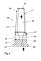
- a blade 10 of a gas turbine comprises an airfoil 14 with a leading edge 17 and a trailing edge 16.
- the airfoil 14 extends along a longitudinal axis X of said blade between a lower end and a blade tip 15.
- a blade root 12 is provided for being attached to a groove 31 in a rotor 11 of said gas turbine.
- a hollow blade core 18 is arranged within said airfoil 14 and extends along the longitudinal axis X between said blade root 12 and said blade tip 1.
- the blade core 18 is provided for the flow of a cooling fluid, which enters said blade core 18 through a blade inlet 20 at said blade root 12 and exits said blade core 18 through at least one dust hole (not shown in Fig. 1, 2 ) at said blade tip 15.
- the cooling fluid (cooling air) is supplied by means of a rotor bore 19, which runs through the rotor 11 and is in fluid communication with said blade inlet 20 of said blade 10.
- the direction of the rotor bore 19 is aligned with the blade orientation, i.e. the longitudinal axis X.
- a unique passage smoothly distributes the flow all over the cross section of the duct further above the blade inlet 20.
- the area/shape of the rotor bore exit 19, which is cylindrical, and the inlet 20 of the blade, which is race-track shaped, are different, leading to a noncontinuous interface (see Fig. 3 , the common area is shaded).
- a rotor bore is provided with a diffuser-shaped rotor bore exit, such that the cross section area of the rotor bore exit at the interface between rotor bore and blade inlet covers the cross section area of the blade inlet.
- an interface plenum is provided at the interface of said blade inlet and said rotor bore exit between the bottom surface of said blade root and the upper surface of said blade-root-receiving rotor groove, said interface plenum being designed to have a plenum bleed of cooling fluid to the outside of the blade root at the leading edge side or trailing edge side.
- said blade root has a blade root height h in longitudinal direction
- said blade core is split into a plurality of parallel cooling fluid ducts, wherein each of said cooling fluid ducts is in fluid communication with said blade inlet and has a dust hole at said blade tip, wherein a plurality of longitudinally extending not necessarily parallel webs is provided within said blade core for splitting said blade core into said plurality of cooling fluid ducts, and wherein, for an optimized cooling of said blade, an individual cross section area and an individual cooling fluid mass flow is associated with each of said plurality of cooling fluid ducts.
- said individual cross section areas and/or said individual cooling fluid mass flows of said cooling fluid ducts are equal within ⁇ 25%.
- said rotor bore is obliquely positioned in a axial plane with respect to said longitudinal axis of said blade, wherein the angle ⁇ of deviation between said rotor bore and said longitudinal axis is in the range 0° ⁇
- ⁇ 30°, and preferably ⁇ 13°.
- said diffuser-shaped rotor bore exit has a diffuser angle ⁇ , consisting of the angles ⁇ 1 and ⁇ 2 .
- the angular aperture of the both angles can be 7° ⁇ ⁇ 1 ⁇ 13°, and 7° ⁇ ⁇ 2 ⁇ 13°.
- an individual cross section area A 1 , A 2 , A 3 and an individual cooling fluid mass flow m 1 , m 2 , m 3 is associated with each of ducts 27a, 27b, 27c.
- the individual cross section areas A 1 , A 2 , A 3 and/or the individual cooling fluid mass flows m 1 , m 2 , m 3 of the ducts 27a, 27b, 27c are chosen to be equal with each other within ⁇ 25%.
- the rotor bore 23 is obliquely positioned in a axial plane with respect to the longitudinal axis X of the blade 10, 30, whereby the angle ⁇ of deviation between the rotor bore 23 and the longitudinal axis X is in the range 0° ⁇
- ⁇ 13°.
- the diffuser-shaped rotor bore exit 24 has a diffuser angles ⁇ 1 and ⁇ 2 .
- the angular aperture of the both angles can be 7° ⁇ ⁇ 1 ⁇ 13°, and 7° ⁇ ⁇ 2 ⁇ 13°.
- the blade root 12 has a blade root height h in longitudinal direction
Landscapes
- Engineering & Computer Science (AREA)
- Mechanical Engineering (AREA)
- General Engineering & Computer Science (AREA)
- Turbine Rotor Nozzle Sealing (AREA)
Priority Applications (8)
| Application Number | Priority Date | Filing Date | Title |
|---|---|---|---|
| EP09155854A EP2236746A1 (fr) | 2009-03-23 | 2009-03-23 | Turbine à gaz |
| RU2011142732/06A RU2531839C2 (ru) | 2009-03-23 | 2010-03-22 | Газовая турбина |
| EP10710027.3A EP2411629B1 (fr) | 2009-03-23 | 2010-03-22 | Turbine à gaz |
| MX2011009617A MX340308B (es) | 2009-03-23 | 2010-03-22 | Turbina de gas. |
| PCT/EP2010/053670 WO2010108879A1 (fr) | 2009-03-23 | 2010-03-22 | Turbine à gaz |
| KR1020117022161A KR101613866B1 (ko) | 2009-03-23 | 2010-03-22 | 가스 터빈 |
| SG2011068152A SG174494A1 (en) | 2009-03-23 | 2010-03-22 | Gas turbine |
| US13/239,549 US9341069B2 (en) | 2009-03-23 | 2011-09-22 | Gas turbine |
Applications Claiming Priority (1)
| Application Number | Priority Date | Filing Date | Title |
|---|---|---|---|
| EP09155854A EP2236746A1 (fr) | 2009-03-23 | 2009-03-23 | Turbine à gaz |
Publications (1)
| Publication Number | Publication Date |
|---|---|
| EP2236746A1 true EP2236746A1 (fr) | 2010-10-06 |
Family
ID=40875154
Family Applications (2)
| Application Number | Title | Priority Date | Filing Date |
|---|---|---|---|
| EP09155854A Withdrawn EP2236746A1 (fr) | 2009-03-23 | 2009-03-23 | Turbine à gaz |
| EP10710027.3A Active EP2411629B1 (fr) | 2009-03-23 | 2010-03-22 | Turbine à gaz |
Family Applications After (1)
| Application Number | Title | Priority Date | Filing Date |
|---|---|---|---|
| EP10710027.3A Active EP2411629B1 (fr) | 2009-03-23 | 2010-03-22 | Turbine à gaz |
Country Status (7)
| Country | Link |
|---|---|
| US (1) | US9341069B2 (fr) |
| EP (2) | EP2236746A1 (fr) |
| KR (1) | KR101613866B1 (fr) |
| MX (1) | MX340308B (fr) |
| RU (1) | RU2531839C2 (fr) |
| SG (1) | SG174494A1 (fr) |
| WO (1) | WO2010108879A1 (fr) |
Cited By (3)
| Publication number | Priority date | Publication date | Assignee | Title |
|---|---|---|---|---|
| CH704716A1 (de) * | 2011-03-22 | 2012-09-28 | Alstom Technology Ltd | Rotorscheibe für eine Turbine sowie Rotor und Turbine mit einer solchen Rotorscheibe. |
| EP2535515A1 (fr) * | 2011-06-16 | 2012-12-19 | Siemens Aktiengesellschaft | Section d'ancrage de pale de rotor dotée d'un passage de refroidissement et procédé pour la fourniture de liquide de refroidissement à une pale de rotor |
| EP3336313A1 (fr) * | 2016-12-19 | 2018-06-20 | Rolls-Royce Deutschland Ltd & Co KG | Ensemble d'aube mobile pour turbines d'une turbine turbine à gaz et procédé de fourniture d'air sceau dans un ensemble d'aube mobile pour turbines |
Families Citing this family (6)
| Publication number | Priority date | Publication date | Assignee | Title |
|---|---|---|---|---|
| EP2725191B1 (fr) | 2012-10-23 | 2016-03-16 | Alstom Technology Ltd | Turbine à gaz et aube de turbine pour une telle turbine à gaz |
| WO2015088823A1 (fr) * | 2013-12-12 | 2015-06-18 | United Technologies Corporation | Refroidissement par vaporisation de rotor de compresseur de moteur de turbine à gaz |
| EP3059394B1 (fr) * | 2015-02-18 | 2019-10-30 | Ansaldo Energia Switzerland AG | Aube de turbine et ensemble d'aubes de turbine |
| US11008872B2 (en) | 2018-12-14 | 2021-05-18 | Raytheon Technologies Corporation | Extension air feed hole blockage preventer for a gas turbine engine |
| US11073024B2 (en) | 2018-12-14 | 2021-07-27 | Raytheon Technologies Corporation | Shape recessed surface cooling air feed hole blockage preventer for a gas turbine engine |
| US11078796B2 (en) | 2018-12-14 | 2021-08-03 | Raytheon Technologies Corporation | Redundant entry cooling air feed hole blockage preventer for a gas turbine engine |
Citations (8)
| Publication number | Priority date | Publication date | Assignee | Title |
|---|---|---|---|---|
| GB611044A (en) * | 1944-03-03 | 1948-10-25 | Rateau Soc | Improvements in or relating to wheels of turbines and the like machines |
| US2657902A (en) * | 1947-12-17 | 1953-11-03 | Packard Motor Car Co | Turbine rotor for turbojet engines |
| GB868788A (en) * | 1956-11-20 | 1961-05-25 | Robert Pouit | Improvements in gas turbine installations |
| FR2152437A1 (fr) * | 1971-09-15 | 1973-04-27 | Snecma | |
| US3749514A (en) * | 1971-09-30 | 1973-07-31 | United Aircraft Corp | Blade attachment |
| JPS5951103A (ja) * | 1982-09-20 | 1984-03-24 | Fuji Electric Co Ltd | タ−ビン動翼及び円板の冷却装置 |
| EP1041246A1 (fr) * | 1999-03-29 | 2000-10-04 | Siemens Aktiengesellschaft | Aube de turbine à gaz coulée avec refroidissement interne, procédé et dispositif de fabrication d'un collecteur dans l'aube de turbine à gaz |
| US6874992B2 (en) | 2001-11-27 | 2005-04-05 | Rolls-Royce Plc | Gas turbine engine aerofoil |
Family Cites Families (20)
| Publication number | Priority date | Publication date | Assignee | Title |
|---|---|---|---|---|
| US2648520A (en) * | 1949-08-02 | 1953-08-11 | Heinz E Schmitt | Air-cooled turbine blade |
| US2951340A (en) * | 1956-01-03 | 1960-09-06 | Curtiss Wright Corp | Gas turbine with control mechanism for turbine cooling air |
| US3370830A (en) * | 1966-12-12 | 1968-02-27 | Gen Motors Corp | Turbine cooling |
| US3918835A (en) * | 1974-12-19 | 1975-11-11 | United Technologies Corp | Centrifugal cooling air filter |
| US4017209A (en) * | 1975-12-15 | 1977-04-12 | United Technologies Corporation | Turbine rotor construction |
| GB1551678A (en) * | 1978-03-20 | 1979-08-30 | Rolls Royce | Cooled rotor blade for a gas turbine engine |
| US4344738A (en) * | 1979-12-17 | 1982-08-17 | United Technologies Corporation | Rotor disk structure |
| US4501053A (en) * | 1982-06-14 | 1985-02-26 | United Technologies Corporation | Method of making rotor blade for a rotary machine |
| US4820123A (en) * | 1988-04-25 | 1989-04-11 | United Technologies Corporation | Dirt removal means for air cooled blades |
| US4820122A (en) * | 1988-04-25 | 1989-04-11 | United Technologies Corporation | Dirt removal means for air cooled blades |
| US5503527A (en) | 1994-12-19 | 1996-04-02 | General Electric Company | Turbine blade having tip slot |
| GB9615394D0 (en) * | 1996-07-23 | 1996-09-04 | Rolls Royce Plc | Gas turbine engine rotor disc with cooling fluid passage |
| DE10064269A1 (de) | 2000-12-22 | 2002-07-04 | Alstom Switzerland Ltd | Komponente einer Strömungsmaschine mit Inspektionsöffnung |
| US6735956B2 (en) * | 2001-10-26 | 2004-05-18 | Pratt & Whitney Canada Corp. | High pressure turbine blade cooling scoop |
| DE10331635B4 (de) * | 2003-07-12 | 2014-02-13 | Alstom Technology Ltd. | Gekühlte Schaufel für eine Gasturbine |
| US7059825B2 (en) * | 2004-05-27 | 2006-06-13 | United Technologies Corporation | Cooled rotor blade |
| US7097419B2 (en) * | 2004-07-26 | 2006-08-29 | General Electric Company | Common tip chamber blade |
| US7632071B2 (en) * | 2005-12-15 | 2009-12-15 | United Technologies Corporation | Cooled turbine blade |
| RU2323343C2 (ru) * | 2006-03-20 | 2008-04-27 | Федеральное государственное унитарное предприятие "Московское машиностроительное производственное предприятие "САЛЮТ" (ФГУП "ММПП "САЛЮТ") | Охлаждаемая лопатка турбомашины |
| US7762774B2 (en) * | 2006-12-15 | 2010-07-27 | Siemens Energy, Inc. | Cooling arrangement for a tapered turbine blade |
-
2009
- 2009-03-23 EP EP09155854A patent/EP2236746A1/fr not_active Withdrawn
-
2010
- 2010-03-22 KR KR1020117022161A patent/KR101613866B1/ko not_active Expired - Fee Related
- 2010-03-22 WO PCT/EP2010/053670 patent/WO2010108879A1/fr not_active Ceased
- 2010-03-22 RU RU2011142732/06A patent/RU2531839C2/ru active
- 2010-03-22 SG SG2011068152A patent/SG174494A1/en unknown
- 2010-03-22 EP EP10710027.3A patent/EP2411629B1/fr active Active
- 2010-03-22 MX MX2011009617A patent/MX340308B/es active IP Right Grant
-
2011
- 2011-09-22 US US13/239,549 patent/US9341069B2/en not_active Expired - Fee Related
Patent Citations (8)
| Publication number | Priority date | Publication date | Assignee | Title |
|---|---|---|---|---|
| GB611044A (en) * | 1944-03-03 | 1948-10-25 | Rateau Soc | Improvements in or relating to wheels of turbines and the like machines |
| US2657902A (en) * | 1947-12-17 | 1953-11-03 | Packard Motor Car Co | Turbine rotor for turbojet engines |
| GB868788A (en) * | 1956-11-20 | 1961-05-25 | Robert Pouit | Improvements in gas turbine installations |
| FR2152437A1 (fr) * | 1971-09-15 | 1973-04-27 | Snecma | |
| US3749514A (en) * | 1971-09-30 | 1973-07-31 | United Aircraft Corp | Blade attachment |
| JPS5951103A (ja) * | 1982-09-20 | 1984-03-24 | Fuji Electric Co Ltd | タ−ビン動翼及び円板の冷却装置 |
| EP1041246A1 (fr) * | 1999-03-29 | 2000-10-04 | Siemens Aktiengesellschaft | Aube de turbine à gaz coulée avec refroidissement interne, procédé et dispositif de fabrication d'un collecteur dans l'aube de turbine à gaz |
| US6874992B2 (en) | 2001-11-27 | 2005-04-05 | Rolls-Royce Plc | Gas turbine engine aerofoil |
Cited By (5)
| Publication number | Priority date | Publication date | Assignee | Title |
|---|---|---|---|---|
| CH704716A1 (de) * | 2011-03-22 | 2012-09-28 | Alstom Technology Ltd | Rotorscheibe für eine Turbine sowie Rotor und Turbine mit einer solchen Rotorscheibe. |
| EP2535515A1 (fr) * | 2011-06-16 | 2012-12-19 | Siemens Aktiengesellschaft | Section d'ancrage de pale de rotor dotée d'un passage de refroidissement et procédé pour la fourniture de liquide de refroidissement à une pale de rotor |
| US9664051B2 (en) | 2011-06-16 | 2017-05-30 | Siemens Aktiengesellschaft | Rotor blade root section with cooling passage and method for supplying cooling fluid to a rotor blade |
| EP3336313A1 (fr) * | 2016-12-19 | 2018-06-20 | Rolls-Royce Deutschland Ltd & Co KG | Ensemble d'aube mobile pour turbines d'une turbine turbine à gaz et procédé de fourniture d'air sceau dans un ensemble d'aube mobile pour turbines |
| US10619490B2 (en) | 2016-12-19 | 2020-04-14 | Rolls-Royce Deutschland Ltd & Co Kg | Turbine rotor blade arrangement for a gas turbine and method for the provision of sealing air in a turbine rotor blade arrangement |
Also Published As
| Publication number | Publication date |
|---|---|
| US20120087782A1 (en) | 2012-04-12 |
| KR101613866B1 (ko) | 2016-04-20 |
| MX2011009617A (es) | 2011-09-29 |
| SG174494A1 (en) | 2011-10-28 |
| MX340308B (es) | 2016-07-05 |
| EP2411629B1 (fr) | 2018-03-07 |
| RU2531839C2 (ru) | 2014-10-27 |
| US9341069B2 (en) | 2016-05-17 |
| RU2011142732A (ru) | 2013-04-27 |
| KR20120005444A (ko) | 2012-01-16 |
| EP2411629A1 (fr) | 2012-02-01 |
| WO2010108879A1 (fr) | 2010-09-30 |
Similar Documents
| Publication | Publication Date | Title |
|---|---|---|
| EP2411629B1 (fr) | Turbine à gaz | |
| JP4659206B2 (ja) | 勾配付きフイルム冷却を備えるタービンノズル | |
| EP2728117B1 (fr) | Extrémité d'aube de turbine munie d'un rebord décalé avec des trous de diffuseur | |
| EP2564028B1 (fr) | Aube de turbine a gaz | |
| US7887294B1 (en) | Turbine airfoil with continuous curved diffusion film holes | |
| EP1091092B1 (fr) | Aube refroidissable pour turbine à gaz | |
| US8721285B2 (en) | Turbine blade with incremental serpentine cooling channels beneath a thermal skin | |
| EP2564029B1 (fr) | Pale de turbine a gaz | |
| EP2682565B1 (fr) | Pale refroidie pour une turbine à gaz | |
| JP5503140B2 (ja) | 発散型タービンノズル | |
| EP1561902B1 (fr) | Aube de turbine avec promoteurs de turbulence | |
| EP2615245B1 (fr) | Aube de turbine refroidie par couche d'air comportant des segments de rainure à la surface extérieure | |
| EP1826361B1 (fr) | Aube de turbine à gaz | |
| EP1865152B1 (fr) | Microcircuits de refroidissement pour aubes de turbine | |
| US7762775B1 (en) | Turbine airfoil with cooled thin trailing edge | |
| US20190186272A1 (en) | Engine component with cooling hole | |
| US20220145764A1 (en) | Component for a turbine engine with a cooling hole | |
| US20170122112A1 (en) | Controlling cooling flow in a cooled turbine vane or blade using an impingement tube | |
| EP1538305B1 (fr) | Aube comprenant un arrangement à densité variable d'entretoises au niveau du bord de fuite | |
| EP3669054B1 (fr) | Aube de turbine et procédé de maintenance correspondant | |
| US10570773B2 (en) | Turbine shroud cooling | |
| US10760431B2 (en) | Component for a turbine engine with a cooling hole | |
| EP2180141A1 (fr) | Aube refroidie pour turbine à gaz, procédé de fabrication d'une telle aube et turbine à gaz comprenant une telle aube | |
| CN113250758B (zh) | 涡轮喷嘴部段和包括这种涡轮喷嘴部段的涡轮喷嘴 | |
| US20250163813A1 (en) | Airfoil assembly with platform cooling |
Legal Events
| Date | Code | Title | Description |
|---|---|---|---|
| PUAI | Public reference made under article 153(3) epc to a published international application that has entered the european phase |
Free format text: ORIGINAL CODE: 0009012 |
|
| AK | Designated contracting states |
Kind code of ref document: A1 Designated state(s): AT BE BG CH CY CZ DE DK EE ES FI FR GB GR HR HU IE IS IT LI LT LU LV MC MK MT NL NO PL PT RO SE SI SK TR |
|
| AX | Request for extension of the european patent |
Extension state: AL BA RS |
|
| AKY | No designation fees paid | ||
| REG | Reference to a national code |
Ref country code: DE Ref legal event code: R108 Effective date: 20110526 |
|
| STAA | Information on the status of an ep patent application or granted ep patent |
Free format text: STATUS: THE APPLICATION IS DEEMED TO BE WITHDRAWN |
|
| 18D | Application deemed to be withdrawn |
Effective date: 20110407 |