EP2236749A2 - Rotorschaufel mit Kühlrille and der Spitze - Google Patents
Rotorschaufel mit Kühlrille and der Spitze Download PDFInfo
- Publication number
- EP2236749A2 EP2236749A2 EP10250286A EP10250286A EP2236749A2 EP 2236749 A2 EP2236749 A2 EP 2236749A2 EP 10250286 A EP10250286 A EP 10250286A EP 10250286 A EP10250286 A EP 10250286A EP 2236749 A2 EP2236749 A2 EP 2236749A2
- Authority
- EP
- European Patent Office
- Prior art keywords
- blade
- groove
- shelf
- blade tip
- tip
- Prior art date
- Legal status (The legal status is an assumption and is not a legal conclusion. Google has not performed a legal analysis and makes no representation as to the accuracy of the status listed.)
- Granted
Links
- 238000001816 cooling Methods 0.000 title claims description 10
- 238000007789 sealing Methods 0.000 claims abstract description 34
- 239000012530 fluid Substances 0.000 claims abstract description 23
- 238000000034 method Methods 0.000 claims description 3
- 239000007789 gas Substances 0.000 description 6
- 239000000567 combustion gas Substances 0.000 description 3
- 230000006835 compression Effects 0.000 description 3
- 238000007906 compression Methods 0.000 description 3
- 239000000446 fuel Substances 0.000 description 2
- 238000002485 combustion reaction Methods 0.000 description 1
- 238000004891 communication Methods 0.000 description 1
- 239000012809 cooling fluid Substances 0.000 description 1
- 230000007423 decrease Effects 0.000 description 1
- 230000009429 distress Effects 0.000 description 1
- 238000009760 electrical discharge machining Methods 0.000 description 1
- 238000000605 extraction Methods 0.000 description 1
- 238000003754 machining Methods 0.000 description 1
- 238000012986 modification Methods 0.000 description 1
- 230000004048 modification Effects 0.000 description 1
Images


Classifications
-
- F—MECHANICAL ENGINEERING; LIGHTING; HEATING; WEAPONS; BLASTING
- F01—MACHINES OR ENGINES IN GENERAL; ENGINE PLANTS IN GENERAL; STEAM ENGINES
- F01D—NON-POSITIVE DISPLACEMENT MACHINES OR ENGINES, e.g. STEAM TURBINES
- F01D5/00—Blades; Blade-carrying members; Heating, heat-insulating, cooling or antivibration means on the blades or the members
- F01D5/12—Blades
- F01D5/14—Form or construction
- F01D5/20—Specially-shaped blade tips to seal space between tips and stator
-
- F—MECHANICAL ENGINEERING; LIGHTING; HEATING; WEAPONS; BLASTING
- F01—MACHINES OR ENGINES IN GENERAL; ENGINE PLANTS IN GENERAL; STEAM ENGINES
- F01D—NON-POSITIVE DISPLACEMENT MACHINES OR ENGINES, e.g. STEAM TURBINES
- F01D5/00—Blades; Blade-carrying members; Heating, heat-insulating, cooling or antivibration means on the blades or the members
- F01D5/12—Blades
- F01D5/14—Form or construction
- F01D5/18—Hollow blades, i.e. blades with cooling or heating channels or cavities; Heating, heat-insulating or cooling means on blades
- F01D5/186—Film cooling
-
- F—MECHANICAL ENGINEERING; LIGHTING; HEATING; WEAPONS; BLASTING
- F05—INDEXING SCHEMES RELATING TO ENGINES OR PUMPS IN VARIOUS SUBCLASSES OF CLASSES F01-F04
- F05D—INDEXING SCHEME FOR ASPECTS RELATING TO NON-POSITIVE-DISPLACEMENT MACHINES OR ENGINES, GAS-TURBINES OR JET-PROPULSION PLANTS
- F05D2240/00—Components
- F05D2240/10—Stators
- F05D2240/12—Fluid guiding means, e.g. vanes
- F05D2240/122—Fluid guiding means, e.g. vanes related to the trailing edge of a stator vane
-
- F—MECHANICAL ENGINEERING; LIGHTING; HEATING; WEAPONS; BLASTING
- F05—INDEXING SCHEMES RELATING TO ENGINES OR PUMPS IN VARIOUS SUBCLASSES OF CLASSES F01-F04
- F05D—INDEXING SCHEME FOR ASPECTS RELATING TO NON-POSITIVE-DISPLACEMENT MACHINES OR ENGINES, GAS-TURBINES OR JET-PROPULSION PLANTS
- F05D2240/00—Components
- F05D2240/20—Rotors
- F05D2240/30—Characteristics of rotor blades, i.e. of any element transforming dynamic fluid energy to or from rotational energy and being attached to a rotor
- F05D2240/304—Characteristics of rotor blades, i.e. of any element transforming dynamic fluid energy to or from rotational energy and being attached to a rotor related to the trailing edge of a rotor blade
-
- F—MECHANICAL ENGINEERING; LIGHTING; HEATING; WEAPONS; BLASTING
- F05—INDEXING SCHEMES RELATING TO ENGINES OR PUMPS IN VARIOUS SUBCLASSES OF CLASSES F01-F04
- F05D—INDEXING SCHEME FOR ASPECTS RELATING TO NON-POSITIVE-DISPLACEMENT MACHINES OR ENGINES, GAS-TURBINES OR JET-PROPULSION PLANTS
- F05D2260/00—Function
- F05D2260/20—Heat transfer, e.g. cooling
- F05D2260/202—Heat transfer, e.g. cooling by film cooling
Definitions
- This application relates to communicating fluid through a groove to cool a blade tip.
- Gas turbine engines are known and typically include multiple sections, such as a fan section, a compression section, a combustor section, a turbine section, and an exhaust nozzle section. Blades within the compressor and turbine sections are often mounted for rotation about an axis. The blades have airfoils extending radially from a mounting platform toward a blade tip.
- Rotating blades compress air in the compression section.
- the compressed air mixes with fuel and is combusted in the combustor section. Products of the combustion expand to rotatably drive blades in the turbine section.
- blades are often exposed to extreme temperatures.
- Some blades include internal features, such as channels, for routing cooling air.
- Some blades include external features, such as blade shelves, for routing cooling air.
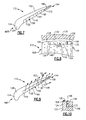
- a prior art blade tip 10 includes a blade shelf 14 having a shelf floor 18 that is radially spaced from a sealing surface 22.
- the blade shelf 14 distributes cooling airflow from holes 26 to some areas of the blade tip 10.
- the sealing surface 22 contacts another portion of the engine (not shown) to create a seal that facilitates work extraction.
- regions near a trailing edge 30 of the blade tip 10 experience significant distress over time due to ineffective distribution of cooling airflow from the holes 26 to these regions.
- the blade shelf 14a extends to a trailing edge 30a of the blade tip 10a.
- the blade shelf 14a extending to the trailing edge 30a weakens the blade tip 10a and significantly decreases the sealing surface, which degrades performance of the engine.
- An example turbine blade includes a blade having an airfoil profile extending radially toward a blade tip.
- a shelf is established in the blade tip.
- a sealing portion of the blade tip extends radially past a floor of the shelf. The sealing portion extends from a blade tip leading edge to a blade tip trailing edge.
- a groove is established in the blade tip. The groove extends from adjacent the shelf to adjacent the blade tip trailing edge. The groove is configured to communicate a fluid from a position adjacent the shelf to a position adjacent the blade tip trailing edge.
- Another example turbine blade includes a blade tip having a suction side and a pressure side.
- the blade tip extends from a leading edge portion of a blade to a trailing edge portion of the blade.
- a shelf is established in the pressure side of the blade tip.
- a groove is established in the blade tip. The groove is configured to communicate fluid from the shelf to the trailing edge portion of the blade.
- An example method of cooling a blade includes communicating a fluid through a blade to a blade shelf near a tip of the blade, moving a portion of the fluid across a portion of a blade tip sealing surface that extends from a blade tip leading edge to a blade tip trailing edge, and communicating another portion of the fluid from the blade shelf to a blade tip trailing edge within a groove that is established in the blade tip.
- FIG. 5 schematically illustrates an example gas turbine engine 50 including (in serial flow communication) a fan section 54, a low-pressure compressor 58, a high-pressure compressor 62, a combustor 66, a high-pressure turbine 70, and a low-pressure turbine 74.
- the gas turbine engine 50 is circumferentially disposed about an engine centerline X.
- air is pulled into the gas turbine engine 50 by the fan section 54, pressurized by the compressors 58 and 62, mixed with fuel, and burned in the combustor 66.
- the high and low-pressure turbines 70 and 74 extract energy from the hot combustion gases flowing from the combustor 66.
- the high-pressure turbine 70 utilizes the extracted energy from the hot combustion gases to power the high-pressure compressor 62 through a high speed shaft 78
- the low-pressure turbine 74 utilizes the energy extracted from the hot combustion gases to power the low-pressure compressor 58 and the fan section 54 through a low speed shaft 82.
- the examples described in this disclosure are not limited to the two-spool engine architecture described however, and may be used with other architectures, such as a single-spool axial design, a three-spool axial design, and still other architectures. That is, there are various types of engines that could benefit from the examples disclosed herein, which are not limited to the design shown.
- an example blade 100 from the high-pressure turbine 70 includes an airfoil profile 104 radially extending from a base 108 to a blade tip 112.
- a fluid 136 such as air, communicates from a fluid supply 116 through an interior of the blade 100 and exits at a plurality of exit holes 120 established by the blade 100.
- the blade tip 112 includes a sealing portion 124 having a sealing surface 128 that is operative to seal against another portion of the gas turbine engine 50, such as a surface 132 of a blade outer air seal 134.
- portions of the sealing surface 128 contact the blade outer air seal 134 to provide a seal.
- Other portions of the sealing surface 128 are spaced from the blade outer air seal 134 approximately 0.508 to 0.762 mm and rely in part on the fluid 136 to provide the seal.
- the fluid 136 cools the blade tip 112 and facilitates maintaining a seal between the sealing surface 128 and the surface 132 as the high-pressure turbine 70 operates.
- the sealing portion 124 and the sealing surface 128 extend axially from a leading edge 140 of the blade 100 to a trailing edge 144 of the blade 100.
- the sealing portion 124 and the sealing surface 128 also extend from a pressure side 148 of the blade 100 to a suction side 152 of the blade 100.
- the blade tip 112 establishes a shelf 156 having a shelf floor 160 that is radially spaced from the sealing surface 128, such that the sealing surface 128 is further from the engine centerline X than the shelf floor 160.
- a plurality of shelf walls 164 span between the shelf floor 160 and the sealing surface 128.
- the shelf floor 160 and the shelf walls 164 both include some of the exit holes 120 in this example. In other examples the shelf floor 160 or the shelf walls 164 lack the exit holes 120.
- the example sealing portion 124 establishes a groove 168 that extends axially from the shelf 156 to the trailing edge 144 of the blade 100.
- the sealing portion 124 is generally defined as the portion of the blade tip 112 extending radially past the shelf floor 160.
- the groove 168 radially terminates at a groove floor 172 that is aligned with the shelf floor 160 in this example.
- the example groove 168 has a rectangular cross-section in this example and is generally aligned with a portion of the pressure side 148.
- a machining operation such as an Electrical Discharge Machining, is used to form the groove 168 in one example.
- the example shelf 156 is established on the pressure side 148 of the blade 100, and the width of the shelf 156 is greater than the width of the groove 168.
- the width of the groove is between 0.254 - 0.508 mm, which is approximately the diameter of the exit holes 120.
- the radial depth of the example shelf is between 0.762 - 1.270 mm.
- the groove floor 172 is aligned generally with the shelf floor 160, other examples may include different sizes of the groove 168 and different relationships between the groove 168 and the shelf 156.
- the groove 168 does not include exit holes 120 in this example, but other examples may.
Landscapes
- Engineering & Computer Science (AREA)
- Mechanical Engineering (AREA)
- General Engineering & Computer Science (AREA)
- Turbine Rotor Nozzle Sealing (AREA)
Applications Claiming Priority (1)
| Application Number | Priority Date | Filing Date | Title |
|---|---|---|---|
| US12/402,571 US8092179B2 (en) | 2009-03-12 | 2009-03-12 | Blade tip cooling groove |
Publications (3)
| Publication Number | Publication Date |
|---|---|
| EP2236749A2 true EP2236749A2 (de) | 2010-10-06 |
| EP2236749A3 EP2236749A3 (de) | 2013-12-25 |
| EP2236749B1 EP2236749B1 (de) | 2016-02-10 |
Family
ID=42115687
Family Applications (1)
| Application Number | Title | Priority Date | Filing Date |
|---|---|---|---|
| EP10250286.1A Not-in-force EP2236749B1 (de) | 2009-03-12 | 2010-02-18 | Turbinenlaufschaufel und zugehöriges Kühlverfahren |
Country Status (2)
| Country | Link |
|---|---|
| US (1) | US8092179B2 (de) |
| EP (1) | EP2236749B1 (de) |
Cited By (1)
| Publication number | Priority date | Publication date | Assignee | Title |
|---|---|---|---|---|
| WO2014137443A2 (en) | 2012-12-28 | 2014-09-12 | United Technologies Corporation | Gas turbine engine turbine blade tip cooling |
Families Citing this family (20)
| Publication number | Priority date | Publication date | Assignee | Title |
|---|---|---|---|---|
| US8500411B2 (en) * | 2010-06-07 | 2013-08-06 | Siemens Energy, Inc. | Turbine airfoil with outer wall thickness indicators |
| US9429027B2 (en) | 2012-04-05 | 2016-08-30 | United Technologies Corporation | Turbine airfoil tip shelf and squealer pocket cooling |
| CN104204453B (zh) | 2012-04-23 | 2019-03-08 | 博格华纳公司 | 带横向凹槽的涡轮增压器护罩以及结合有该护罩的涡轮增压器 |
| CN104204444B (zh) * | 2012-04-23 | 2017-06-30 | 博格华纳公司 | 具有轮廓边缘离隙的涡轮增压器叶片和结合有该涡轮增压器叶片的涡轮增压器 |
| RU2014145610A (ru) | 2012-04-23 | 2016-06-10 | Боргварнер Инк. | Ступица турбины с несплошностью поверхности и турбонагнетатель, содержащий такую ступицу |
| US9777582B2 (en) | 2012-07-03 | 2017-10-03 | United Technologies Corporation | Tip leakage flow directionality control |
| US9957817B2 (en) | 2012-07-03 | 2018-05-01 | United Technologies Corporation | Tip leakage flow directionality control |
| US9951629B2 (en) | 2012-07-03 | 2018-04-24 | United Technologies Corporation | Tip leakage flow directionality control |
| US9260972B2 (en) | 2012-07-03 | 2016-02-16 | United Technologies Corporation | Tip leakage flow directionality control |
| US9334742B2 (en) | 2012-10-05 | 2016-05-10 | General Electric Company | Rotor blade and method for cooling the rotor blade |
| US10329917B2 (en) | 2013-03-05 | 2019-06-25 | United Technologies Corporation | Gas turbine engine component external surface micro-channel cooling |
| US9995147B2 (en) | 2015-02-11 | 2018-06-12 | United Technologies Corporation | Blade tip cooling arrangement |
| US10053992B2 (en) * | 2015-07-02 | 2018-08-21 | United Technologies Corporation | Gas turbine engine airfoil squealer pocket cooling hole configuration |
| US10801325B2 (en) * | 2017-03-27 | 2020-10-13 | Raytheon Technologies Corporation | Turbine blade with tip vortex control and tip shelf |
| US11118462B2 (en) * | 2019-01-24 | 2021-09-14 | Pratt & Whitney Canada Corp. | Blade tip pocket rib |
| US11371359B2 (en) | 2020-11-26 | 2022-06-28 | Pratt & Whitney Canada Corp. | Turbine blade for a gas turbine engine |
| US12006836B2 (en) | 2021-07-02 | 2024-06-11 | Rtx Corporation | Cooling arrangement for gas turbine engine component |
| US11913353B2 (en) | 2021-08-06 | 2024-02-27 | Rtx Corporation | Airfoil tip arrangement for gas turbine engine |
| US11898460B2 (en) | 2022-06-09 | 2024-02-13 | General Electric Company | Turbine engine with a blade |
| US11927111B2 (en) | 2022-06-09 | 2024-03-12 | General Electric Company | Turbine engine with a blade |
Family Cites Families (17)
| Publication number | Priority date | Publication date | Assignee | Title |
|---|---|---|---|---|
| US5261789A (en) * | 1992-08-25 | 1993-11-16 | General Electric Company | Tip cooled blade |
| US5503527A (en) | 1994-12-19 | 1996-04-02 | General Electric Company | Turbine blade having tip slot |
| US5927946A (en) * | 1997-09-29 | 1999-07-27 | General Electric Company | Turbine blade having recuperative trailing edge tip cooling |
| US6422821B1 (en) * | 2001-01-09 | 2002-07-23 | General Electric Company | Method and apparatus for reducing turbine blade tip temperatures |
| US6382913B1 (en) * | 2001-02-09 | 2002-05-07 | General Electric Company | Method and apparatus for reducing turbine blade tip region temperatures |
| US6554575B2 (en) * | 2001-09-27 | 2003-04-29 | General Electric Company | Ramped tip shelf blade |
| US6652235B1 (en) | 2002-05-31 | 2003-11-25 | General Electric Company | Method and apparatus for reducing turbine blade tip region temperatures |
| US6672829B1 (en) * | 2002-07-16 | 2004-01-06 | General Electric Company | Turbine blade having angled squealer tip |
| US6790005B2 (en) | 2002-12-30 | 2004-09-14 | General Electric Company | Compound tip notched blade |
| US7059834B2 (en) | 2003-01-24 | 2006-06-13 | United Technologies Corporation | Turbine blade |
| US6824359B2 (en) | 2003-01-31 | 2004-11-30 | United Technologies Corporation | Turbine blade |
| US6991430B2 (en) * | 2003-04-07 | 2006-01-31 | General Electric Company | Turbine blade with recessed squealer tip and shelf |
| US7118337B2 (en) | 2004-06-17 | 2006-10-10 | Siemens Power Generation, Inc. | Gas turbine airfoil trailing edge corner |
| US7175391B2 (en) | 2004-07-08 | 2007-02-13 | United Technologies Corporation | Turbine blade |
| US7270514B2 (en) * | 2004-10-21 | 2007-09-18 | General Electric Company | Turbine blade tip squealer and rebuild method |
| US7300250B2 (en) | 2005-09-28 | 2007-11-27 | Pratt & Whitney Canada Corp. | Cooled airfoil trailing edge tip exit |
| US7857587B2 (en) * | 2006-11-30 | 2010-12-28 | General Electric Company | Turbine blades and turbine blade cooling systems and methods |
-
2009
- 2009-03-12 US US12/402,571 patent/US8092179B2/en not_active Expired - Fee Related
-
2010
- 2010-02-18 EP EP10250286.1A patent/EP2236749B1/de not_active Not-in-force
Non-Patent Citations (1)
| Title |
|---|
| None |
Cited By (2)
| Publication number | Priority date | Publication date | Assignee | Title |
|---|---|---|---|---|
| WO2014137443A2 (en) | 2012-12-28 | 2014-09-12 | United Technologies Corporation | Gas turbine engine turbine blade tip cooling |
| EP2938831A4 (de) * | 2012-12-28 | 2016-03-02 | United Technologies Corp | Schaufelspitzenkühlung für eine gasturbinenmotorturbine |
Also Published As
| Publication number | Publication date |
|---|---|
| EP2236749B1 (de) | 2016-02-10 |
| US8092179B2 (en) | 2012-01-10 |
| EP2236749A3 (de) | 2013-12-25 |
| US20100232979A1 (en) | 2010-09-16 |
Similar Documents
| Publication | Publication Date | Title |
|---|---|---|
| EP2236749B1 (de) | Turbinenlaufschaufel und zugehöriges Kühlverfahren | |
| US8684691B2 (en) | Turbine blade with chamfered squealer tip and convective cooling holes | |
| US20200277862A1 (en) | Airfoil for a turbine engine | |
| EP2161412B1 (de) | Kühlung von einer Schaufelspitze | |
| US11015453B2 (en) | Engine component with non-diffusing section | |
| EP2374997B1 (de) | Komponent für eine Gasturbine | |
| US20210404344A1 (en) | Blade with tip rail cooling | |
| EP2956627B1 (de) | Gasturbinenmotorkomponente mit kombinierter anpassungsfläche und plattformkühlung | |
| EP3043027B1 (de) | Gasturbinenmotorkomponente mit konformem kehlkühlungspfad | |
| EP3090129B1 (de) | Bauteil eines gasturbinentriebwerks und zugehöriges gasturbinentriebwerk | |
| EP3118414B1 (de) | Gasturbinentriebwerksschaufel | |
| CN107084001A (zh) | 用于燃气涡轮发动机的翼型件 | |
| EP3009600A1 (de) | Turbinenschaufel mit spitzenkühlung eines gasturbinentriebwerks | |
| US20210239004A1 (en) | Airfoil with cooling hole | |
| EP2885520B1 (de) | Bauteil für ein gasturbinentriebwerk und zugehöriges kühlverfahren | |
| WO2014116216A1 (en) | Gas turbine engine component with angled aperture impingement | |
| US7661924B2 (en) | Method and apparatus for assembling turbine engines | |
| US7686576B2 (en) | Method and apparatus for assembling gas turbine engines | |
| EP3650639A1 (de) | Abschirmung für eine turbinentriebwerksschaufel | |
| US10612389B2 (en) | Engine component with porous section | |
| EP3336317B1 (de) | Kühltasche für die plattform einer turbinenleitschaufel | |
| US7534085B2 (en) | Gas turbine engine with contoured air supply slot in turbine rotor | |
| US10508548B2 (en) | Turbine engine with a platform cooling circuit | |
| US11236625B2 (en) | Method of making a cooled airfoil assembly for a turbine engine |
Legal Events
| Date | Code | Title | Description |
|---|---|---|---|
| PUAI | Public reference made under article 153(3) epc to a published international application that has entered the european phase |
Free format text: ORIGINAL CODE: 0009012 |
|
| AK | Designated contracting states |
Kind code of ref document: A2 Designated state(s): AT BE BG CH CY CZ DE DK EE ES FI FR GB GR HR HU IE IS IT LI LT LU LV MC MK MT NL NO PL PT RO SE SI SK SM TR |
|
| AX | Request for extension of the european patent |
Extension state: AL BA RS |
|
| PUAL | Search report despatched |
Free format text: ORIGINAL CODE: 0009013 |
|
| AK | Designated contracting states |
Kind code of ref document: A3 Designated state(s): AT BE BG CH CY CZ DE DK EE ES FI FR GB GR HR HU IE IS IT LI LT LU LV MC MK MT NL NO PL PT RO SE SI SK SM TR |
|
| AX | Request for extension of the european patent |
Extension state: AL BA RS |
|
| RIC1 | Information provided on ipc code assigned before grant |
Ipc: F01D 5/18 20060101AFI20131120BHEP Ipc: F01D 5/20 20060101ALI20131120BHEP |
|
| 17P | Request for examination filed |
Effective date: 20140623 |
|
| RBV | Designated contracting states (corrected) |
Designated state(s): AT BE BG CH CY CZ DE DK EE ES FI FR GB GR HR HU IE IS IT LI LT LU LV MC MK MT NL NO PL PT RO SE SI SK SM TR |
|
| GRAP | Despatch of communication of intention to grant a patent |
Free format text: ORIGINAL CODE: EPIDOSNIGR1 |
|
| INTG | Intention to grant announced |
Effective date: 20150908 |
|
| GRAS | Grant fee paid |
Free format text: ORIGINAL CODE: EPIDOSNIGR3 |
|
| GRAA | (expected) grant |
Free format text: ORIGINAL CODE: 0009210 |
|
| AK | Designated contracting states |
Kind code of ref document: B1 Designated state(s): AT BE BG CH CY CZ DE DK EE ES FI FR GB GR HR HU IE IS IT LI LT LU LV MC MK MT NL NO PL PT RO SE SI SK SM TR |
|
| REG | Reference to a national code |
Ref country code: GB Ref legal event code: FG4D |
|
| REG | Reference to a national code |
Ref country code: AT Ref legal event code: REF Ref document number: 774758 Country of ref document: AT Kind code of ref document: T Effective date: 20160215 Ref country code: CH Ref legal event code: EP |
|
| REG | Reference to a national code |
Ref country code: IE Ref legal event code: FG4D |
|
| REG | Reference to a national code |
Ref country code: DE Ref legal event code: R096 Ref document number: 602010030522 Country of ref document: DE |
|
| REG | Reference to a national code |
Ref country code: LT Ref legal event code: MG4D |
|
| REG | Reference to a national code |
Ref country code: NL Ref legal event code: MP Effective date: 20160210 |
|
| REG | Reference to a national code |
Ref country code: AT Ref legal event code: MK05 Ref document number: 774758 Country of ref document: AT Kind code of ref document: T Effective date: 20160210 |
|
| PG25 | Lapsed in a contracting state [announced via postgrant information from national office to epo] |
Ref country code: ES Free format text: LAPSE BECAUSE OF FAILURE TO SUBMIT A TRANSLATION OF THE DESCRIPTION OR TO PAY THE FEE WITHIN THE PRESCRIBED TIME-LIMIT Effective date: 20160210 Ref country code: GR Free format text: LAPSE BECAUSE OF FAILURE TO SUBMIT A TRANSLATION OF THE DESCRIPTION OR TO PAY THE FEE WITHIN THE PRESCRIBED TIME-LIMIT Effective date: 20160511 Ref country code: IT Free format text: LAPSE BECAUSE OF FAILURE TO SUBMIT A TRANSLATION OF THE DESCRIPTION OR TO PAY THE FEE WITHIN THE PRESCRIBED TIME-LIMIT Effective date: 20160210 Ref country code: HR Free format text: LAPSE BECAUSE OF FAILURE TO SUBMIT A TRANSLATION OF THE DESCRIPTION OR TO PAY THE FEE WITHIN THE PRESCRIBED TIME-LIMIT Effective date: 20160210 Ref country code: FI Free format text: LAPSE BECAUSE OF FAILURE TO SUBMIT A TRANSLATION OF THE DESCRIPTION OR TO PAY THE FEE WITHIN THE PRESCRIBED TIME-LIMIT Effective date: 20160210 Ref country code: NO Free format text: LAPSE BECAUSE OF FAILURE TO SUBMIT A TRANSLATION OF THE DESCRIPTION OR TO PAY THE FEE WITHIN THE PRESCRIBED TIME-LIMIT Effective date: 20160510 |
|
| PG25 | Lapsed in a contracting state [announced via postgrant information from national office to epo] |
Ref country code: LT Free format text: LAPSE BECAUSE OF FAILURE TO SUBMIT A TRANSLATION OF THE DESCRIPTION OR TO PAY THE FEE WITHIN THE PRESCRIBED TIME-LIMIT Effective date: 20160210 Ref country code: SE Free format text: LAPSE BECAUSE OF FAILURE TO SUBMIT A TRANSLATION OF THE DESCRIPTION OR TO PAY THE FEE WITHIN THE PRESCRIBED TIME-LIMIT Effective date: 20160210 Ref country code: BE Free format text: LAPSE BECAUSE OF NON-PAYMENT OF DUE FEES Effective date: 20160229 Ref country code: PL Free format text: LAPSE BECAUSE OF FAILURE TO SUBMIT A TRANSLATION OF THE DESCRIPTION OR TO PAY THE FEE WITHIN THE PRESCRIBED TIME-LIMIT Effective date: 20160210 Ref country code: IS Free format text: LAPSE BECAUSE OF FAILURE TO SUBMIT A TRANSLATION OF THE DESCRIPTION OR TO PAY THE FEE WITHIN THE PRESCRIBED TIME-LIMIT Effective date: 20160610 Ref country code: LV Free format text: LAPSE BECAUSE OF FAILURE TO SUBMIT A TRANSLATION OF THE DESCRIPTION OR TO PAY THE FEE WITHIN THE PRESCRIBED TIME-LIMIT Effective date: 20160210 Ref country code: NL Free format text: LAPSE BECAUSE OF FAILURE TO SUBMIT A TRANSLATION OF THE DESCRIPTION OR TO PAY THE FEE WITHIN THE PRESCRIBED TIME-LIMIT Effective date: 20160210 Ref country code: AT Free format text: LAPSE BECAUSE OF FAILURE TO SUBMIT A TRANSLATION OF THE DESCRIPTION OR TO PAY THE FEE WITHIN THE PRESCRIBED TIME-LIMIT Effective date: 20160210 Ref country code: PT Free format text: LAPSE BECAUSE OF FAILURE TO SUBMIT A TRANSLATION OF THE DESCRIPTION OR TO PAY THE FEE WITHIN THE PRESCRIBED TIME-LIMIT Effective date: 20160613 |
|
| REG | Reference to a national code |
Ref country code: CH Ref legal event code: PL |
|
| RAP2 | Party data changed (patent owner data changed or rights of a patent transferred) |
Owner name: UNITED TECHNOLOGIES CORPORATION |
|
| PG25 | Lapsed in a contracting state [announced via postgrant information from national office to epo] |
Ref country code: DK Free format text: LAPSE BECAUSE OF FAILURE TO SUBMIT A TRANSLATION OF THE DESCRIPTION OR TO PAY THE FEE WITHIN THE PRESCRIBED TIME-LIMIT Effective date: 20160210 Ref country code: LI Free format text: LAPSE BECAUSE OF NON-PAYMENT OF DUE FEES Effective date: 20160229 Ref country code: CH Free format text: LAPSE BECAUSE OF NON-PAYMENT OF DUE FEES Effective date: 20160229 Ref country code: EE Free format text: LAPSE BECAUSE OF FAILURE TO SUBMIT A TRANSLATION OF THE DESCRIPTION OR TO PAY THE FEE WITHIN THE PRESCRIBED TIME-LIMIT Effective date: 20160210 |
|
| REG | Reference to a national code |
Ref country code: DE Ref legal event code: R097 Ref document number: 602010030522 Country of ref document: DE |
|
| PG25 | Lapsed in a contracting state [announced via postgrant information from national office to epo] |
Ref country code: SK Free format text: LAPSE BECAUSE OF FAILURE TO SUBMIT A TRANSLATION OF THE DESCRIPTION OR TO PAY THE FEE WITHIN THE PRESCRIBED TIME-LIMIT Effective date: 20160210 Ref country code: RO Free format text: LAPSE BECAUSE OF FAILURE TO SUBMIT A TRANSLATION OF THE DESCRIPTION OR TO PAY THE FEE WITHIN THE PRESCRIBED TIME-LIMIT Effective date: 20160210 Ref country code: SM Free format text: LAPSE BECAUSE OF FAILURE TO SUBMIT A TRANSLATION OF THE DESCRIPTION OR TO PAY THE FEE WITHIN THE PRESCRIBED TIME-LIMIT Effective date: 20160210 Ref country code: CZ Free format text: LAPSE BECAUSE OF FAILURE TO SUBMIT A TRANSLATION OF THE DESCRIPTION OR TO PAY THE FEE WITHIN THE PRESCRIBED TIME-LIMIT Effective date: 20160210 |
|
| REG | Reference to a national code |
Ref country code: IE Ref legal event code: MM4A |
|
| PLBE | No opposition filed within time limit |
Free format text: ORIGINAL CODE: 0009261 |
|
| STAA | Information on the status of an ep patent application or granted ep patent |
Free format text: STATUS: NO OPPOSITION FILED WITHIN TIME LIMIT |
|
| PG25 | Lapsed in a contracting state [announced via postgrant information from national office to epo] |
Ref country code: BE Free format text: LAPSE BECAUSE OF FAILURE TO SUBMIT A TRANSLATION OF THE DESCRIPTION OR TO PAY THE FEE WITHIN THE PRESCRIBED TIME-LIMIT Effective date: 20160210 |
|
| 26N | No opposition filed |
Effective date: 20161111 |
|
| PG25 | Lapsed in a contracting state [announced via postgrant information from national office to epo] |
Ref country code: IE Free format text: LAPSE BECAUSE OF NON-PAYMENT OF DUE FEES Effective date: 20160218 |
|
| REG | Reference to a national code |
Ref country code: FR Ref legal event code: ST Effective date: 20170102 |
|
| PG25 | Lapsed in a contracting state [announced via postgrant information from national office to epo] |
Ref country code: BG Free format text: LAPSE BECAUSE OF FAILURE TO SUBMIT A TRANSLATION OF THE DESCRIPTION OR TO PAY THE FEE WITHIN THE PRESCRIBED TIME-LIMIT Effective date: 20160510 Ref country code: SI Free format text: LAPSE BECAUSE OF FAILURE TO SUBMIT A TRANSLATION OF THE DESCRIPTION OR TO PAY THE FEE WITHIN THE PRESCRIBED TIME-LIMIT Effective date: 20160210 |
|
| PG25 | Lapsed in a contracting state [announced via postgrant information from national office to epo] |
Ref country code: FR Free format text: LAPSE BECAUSE OF NON-PAYMENT OF DUE FEES Effective date: 20160411 |
|
| REG | Reference to a national code |
Ref country code: DE Ref legal event code: R082 Ref document number: 602010030522 Country of ref document: DE Representative=s name: SCHMITT-NILSON SCHRAUD WAIBEL WOHLFROM PATENTA, DE |
|
| REG | Reference to a national code |
Ref country code: DE Ref legal event code: R082 Ref document number: 602010030522 Country of ref document: DE Representative=s name: SCHMITT-NILSON SCHRAUD WAIBEL WOHLFROM PATENTA, DE Ref country code: DE Ref legal event code: R081 Ref document number: 602010030522 Country of ref document: DE Owner name: UNITED TECHNOLOGIES CORP. (N.D.GES.D. STAATES , US Free format text: FORMER OWNER: UNITED TECHNOLOGIES CORPORATION, HARTFORD, CONN., US |
|
| PG25 | Lapsed in a contracting state [announced via postgrant information from national office to epo] |
Ref country code: MT Free format text: LAPSE BECAUSE OF FAILURE TO SUBMIT A TRANSLATION OF THE DESCRIPTION OR TO PAY THE FEE WITHIN THE PRESCRIBED TIME-LIMIT Effective date: 20160210 |
|
| PG25 | Lapsed in a contracting state [announced via postgrant information from national office to epo] |
Ref country code: CY Free format text: LAPSE BECAUSE OF FAILURE TO SUBMIT A TRANSLATION OF THE DESCRIPTION OR TO PAY THE FEE WITHIN THE PRESCRIBED TIME-LIMIT Effective date: 20160210 Ref country code: HU Free format text: LAPSE BECAUSE OF FAILURE TO SUBMIT A TRANSLATION OF THE DESCRIPTION OR TO PAY THE FEE WITHIN THE PRESCRIBED TIME-LIMIT; INVALID AB INITIO Effective date: 20100218 |
|
| PG25 | Lapsed in a contracting state [announced via postgrant information from national office to epo] |
Ref country code: MK Free format text: LAPSE BECAUSE OF FAILURE TO SUBMIT A TRANSLATION OF THE DESCRIPTION OR TO PAY THE FEE WITHIN THE PRESCRIBED TIME-LIMIT Effective date: 20160210 Ref country code: MC Free format text: LAPSE BECAUSE OF FAILURE TO SUBMIT A TRANSLATION OF THE DESCRIPTION OR TO PAY THE FEE WITHIN THE PRESCRIBED TIME-LIMIT Effective date: 20160210 Ref country code: TR Free format text: LAPSE BECAUSE OF FAILURE TO SUBMIT A TRANSLATION OF THE DESCRIPTION OR TO PAY THE FEE WITHIN THE PRESCRIBED TIME-LIMIT Effective date: 20160210 Ref country code: MT Free format text: LAPSE BECAUSE OF FAILURE TO SUBMIT A TRANSLATION OF THE DESCRIPTION OR TO PAY THE FEE WITHIN THE PRESCRIBED TIME-LIMIT Effective date: 20160229 Ref country code: LU Free format text: LAPSE BECAUSE OF NON-PAYMENT OF DUE FEES Effective date: 20160218 |
|
| REG | Reference to a national code |
Ref country code: DE Ref legal event code: R081 Ref document number: 602010030522 Country of ref document: DE Owner name: RAYTHEON TECHNOLOGIES CORPORATION (N.D.GES.D.S, US Free format text: FORMER OWNER: UNITED TECHNOLOGIES CORP. (N.D.GES.D. STAATES DELAWARE), FARMINGTON, CONN., US |
|
| PGFP | Annual fee paid to national office [announced via postgrant information from national office to epo] |
Ref country code: GB Payment date: 20230121 Year of fee payment: 14 Ref country code: DE Payment date: 20230119 Year of fee payment: 14 |
|
| P01 | Opt-out of the competence of the unified patent court (upc) registered |
Effective date: 20230519 |
|
| REG | Reference to a national code |
Ref country code: DE Ref legal event code: R119 Ref document number: 602010030522 Country of ref document: DE |
|
| GBPC | Gb: european patent ceased through non-payment of renewal fee |
Effective date: 20240218 |
|
| PG25 | Lapsed in a contracting state [announced via postgrant information from national office to epo] |
Ref country code: DE Free format text: LAPSE BECAUSE OF NON-PAYMENT OF DUE FEES Effective date: 20240903 |
|
| PG25 | Lapsed in a contracting state [announced via postgrant information from national office to epo] |
Ref country code: GB Free format text: LAPSE BECAUSE OF NON-PAYMENT OF DUE FEES Effective date: 20240218 |
|
| PG25 | Lapsed in a contracting state [announced via postgrant information from national office to epo] |
Ref country code: GB Free format text: LAPSE BECAUSE OF NON-PAYMENT OF DUE FEES Effective date: 20240218 Ref country code: DE Free format text: LAPSE BECAUSE OF NON-PAYMENT OF DUE FEES Effective date: 20240903 |