EP2236770B1 - Gasturbinenbauteil mit kristalliner Mikrostruktur - Google Patents
Gasturbinenbauteil mit kristalliner Mikrostruktur Download PDFInfo
- Publication number
- EP2236770B1 EP2236770B1 EP10250330.7A EP10250330A EP2236770B1 EP 2236770 B1 EP2236770 B1 EP 2236770B1 EP 10250330 A EP10250330 A EP 10250330A EP 2236770 B1 EP2236770 B1 EP 2236770B1
- Authority
- EP
- European Patent Office
- Prior art keywords
- gaspath
- layer
- recited
- substrate
- gas turbine
- Prior art date
- Legal status (The legal status is an assumption and is not a legal conclusion. Google has not performed a legal analysis and makes no representation as to the accuracy of the status listed.)
- Active
Links
Images


Classifications
-
- F—MECHANICAL ENGINEERING; LIGHTING; HEATING; WEAPONS; BLASTING
- F01—MACHINES OR ENGINES IN GENERAL; ENGINE PLANTS IN GENERAL; STEAM ENGINES
- F01D—NON-POSITIVE DISPLACEMENT MACHINES OR ENGINES, e.g. STEAM TURBINES
- F01D11/00—Preventing or minimising internal leakage of working-fluid, e.g. between stages
- F01D11/08—Preventing or minimising internal leakage of working-fluid, e.g. between stages for sealing space between rotor blade tips and stator
-
- C—CHEMISTRY; METALLURGY
- C23—COATING METALLIC MATERIAL; COATING MATERIAL WITH METALLIC MATERIAL; CHEMICAL SURFACE TREATMENT; DIFFUSION TREATMENT OF METALLIC MATERIAL; COATING BY VACUUM EVAPORATION, BY SPUTTERING, BY ION IMPLANTATION OR BY CHEMICAL VAPOUR DEPOSITION, IN GENERAL; INHIBITING CORROSION OF METALLIC MATERIAL OR INCRUSTATION IN GENERAL
- C23C—COATING METALLIC MATERIAL; COATING MATERIAL WITH METALLIC MATERIAL; SURFACE TREATMENT OF METALLIC MATERIAL BY DIFFUSION INTO THE SURFACE, BY CHEMICAL CONVERSION OR SUBSTITUTION; COATING BY VACUUM EVAPORATION, BY SPUTTERING, BY ION IMPLANTATION OR BY CHEMICAL VAPOUR DEPOSITION, IN GENERAL
- C23C26/00—Coating not provided for in groups C23C2/00 - C23C24/00
-
- C—CHEMISTRY; METALLURGY
- C23—COATING METALLIC MATERIAL; COATING MATERIAL WITH METALLIC MATERIAL; CHEMICAL SURFACE TREATMENT; DIFFUSION TREATMENT OF METALLIC MATERIAL; COATING BY VACUUM EVAPORATION, BY SPUTTERING, BY ION IMPLANTATION OR BY CHEMICAL VAPOUR DEPOSITION, IN GENERAL; INHIBITING CORROSION OF METALLIC MATERIAL OR INCRUSTATION IN GENERAL
- C23C—COATING METALLIC MATERIAL; COATING MATERIAL WITH METALLIC MATERIAL; SURFACE TREATMENT OF METALLIC MATERIAL BY DIFFUSION INTO THE SURFACE, BY CHEMICAL CONVERSION OR SUBSTITUTION; COATING BY VACUUM EVAPORATION, BY SPUTTERING, BY ION IMPLANTATION OR BY CHEMICAL VAPOUR DEPOSITION, IN GENERAL
- C23C30/00—Coating with metallic material characterised only by the composition of the metallic material, i.e. not characterised by the coating process
-
- F—MECHANICAL ENGINEERING; LIGHTING; HEATING; WEAPONS; BLASTING
- F05—INDEXING SCHEMES RELATING TO ENGINES OR PUMPS IN VARIOUS SUBCLASSES OF CLASSES F01-F04
- F05D—INDEXING SCHEME FOR ASPECTS RELATING TO NON-POSITIVE-DISPLACEMENT MACHINES OR ENGINES, GAS-TURBINES OR JET-PROPULSION PLANTS
- F05D2230/00—Manufacture
- F05D2230/20—Manufacture essentially without removing material
- F05D2230/23—Manufacture essentially without removing material by permanently joining parts together
- F05D2230/232—Manufacture essentially without removing material by permanently joining parts together by welding
- F05D2230/237—Brazing
-
- F—MECHANICAL ENGINEERING; LIGHTING; HEATING; WEAPONS; BLASTING
- F05—INDEXING SCHEMES RELATING TO ENGINES OR PUMPS IN VARIOUS SUBCLASSES OF CLASSES F01-F04
- F05D—INDEXING SCHEME FOR ASPECTS RELATING TO NON-POSITIVE-DISPLACEMENT MACHINES OR ENGINES, GAS-TURBINES OR JET-PROPULSION PLANTS
- F05D2230/00—Manufacture
- F05D2230/30—Manufacture with deposition of material
-
- F—MECHANICAL ENGINEERING; LIGHTING; HEATING; WEAPONS; BLASTING
- F05—INDEXING SCHEMES RELATING TO ENGINES OR PUMPS IN VARIOUS SUBCLASSES OF CLASSES F01-F04
- F05D—INDEXING SCHEME FOR ASPECTS RELATING TO NON-POSITIVE-DISPLACEMENT MACHINES OR ENGINES, GAS-TURBINES OR JET-PROPULSION PLANTS
- F05D2240/00—Components
- F05D2240/10—Stators
- F05D2240/11—Shroud seal segments
-
- F—MECHANICAL ENGINEERING; LIGHTING; HEATING; WEAPONS; BLASTING
- F05—INDEXING SCHEMES RELATING TO ENGINES OR PUMPS IN VARIOUS SUBCLASSES OF CLASSES F01-F04
- F05D—INDEXING SCHEME FOR ASPECTS RELATING TO NON-POSITIVE-DISPLACEMENT MACHINES OR ENGINES, GAS-TURBINES OR JET-PROPULSION PLANTS
- F05D2300/00—Materials; Properties thereof
- F05D2300/60—Properties or characteristics given to material by treatment or manufacturing
- F05D2300/605—Crystalline
-
- F—MECHANICAL ENGINEERING; LIGHTING; HEATING; WEAPONS; BLASTING
- F05—INDEXING SCHEMES RELATING TO ENGINES OR PUMPS IN VARIOUS SUBCLASSES OF CLASSES F01-F04
- F05D—INDEXING SCHEME FOR ASPECTS RELATING TO NON-POSITIVE-DISPLACEMENT MACHINES OR ENGINES, GAS-TURBINES OR JET-PROPULSION PLANTS
- F05D2300/00—Materials; Properties thereof
- F05D2300/60—Properties or characteristics given to material by treatment or manufacturing
- F05D2300/606—Directionally-solidified crystalline structures
-
- F—MECHANICAL ENGINEERING; LIGHTING; HEATING; WEAPONS; BLASTING
- F05—INDEXING SCHEMES RELATING TO ENGINES OR PUMPS IN VARIOUS SUBCLASSES OF CLASSES F01-F04
- F05D—INDEXING SCHEME FOR ASPECTS RELATING TO NON-POSITIVE-DISPLACEMENT MACHINES OR ENGINES, GAS-TURBINES OR JET-PROPULSION PLANTS
- F05D2300/00—Materials; Properties thereof
- F05D2300/60—Properties or characteristics given to material by treatment or manufacturing
- F05D2300/608—Microstructure
-
- F—MECHANICAL ENGINEERING; LIGHTING; HEATING; WEAPONS; BLASTING
- F05—INDEXING SCHEMES RELATING TO ENGINES OR PUMPS IN VARIOUS SUBCLASSES OF CLASSES F01-F04
- F05D—INDEXING SCHEME FOR ASPECTS RELATING TO NON-POSITIVE-DISPLACEMENT MACHINES OR ENGINES, GAS-TURBINES OR JET-PROPULSION PLANTS
- F05D2300/00—Materials; Properties thereof
- F05D2300/60—Properties or characteristics given to material by treatment or manufacturing
- F05D2300/611—Coating
Definitions
- the turbine section of a gas turbine engine may include blade outer air seals circumferentially surrounding the turbine blades.
- the blade outer air seals may include a coating to protect from erosion, oxidation, corrosion or the like from hot exhaust gas flowing through the turbine section.
- conventional blade outer air seals may include ceramic coatings, metallic coatings, or both.
- blade outer air seals may include internal cooling passages or back-side impingement cooling to resist the high temperatures of the hot exhaust gases.
- the cooling may produce a considerable thermal gradient through the seals that may cause accelerated seal corrosion and coating/seal cracking to open the cooling passages.
- a gas turbine article having the features of the preamble of claim 1 is disclosed in EP-A-333129 .
- the present invention provides a gas turbine engine article as set forth in claim 1.
- the gas turbine engine article may be a blade outer air seal within a gas turbine engine.
- the gas turbine may include a compressor section, a combustor that is fluidly connected with the compressor section, and a turbine section downstream from the combustor.
- the seal may be included within the turbine section.
- the invention also provides a method of processing a gas turbine engine article, as set forth in claim 8.
- Figure 1 illustrates selected portions of an example gas turbine engine 10, such as a gas turbine engine 10 used for propulsion.
- the gas turbine engine 10 is circumferentially disposed about an engine centerline 12.
- the engine 10 may include a fan 14, a compressor section 16, a combustion section 18, and a turbine section 20 that includes rotating turbine blades 22 and static turbine vanes 24.
- other types of engines may also benefit from the examples disclosed herein, such as engines that do not include a fan or engines having other types of compressors, combustors, and turbines than shown.
- FIG 2 illustrates selected portions of the turbine section 20.
- the turbine blades 22 receive a hot gas flow 26 from the combustion section 18 ( Figure 1 ).
- the turbine section 20 includes a blade outer air seal system 28 having a plurality of seal members 30, or gas turbine engine articles, that function as an outer wall for the hot gas flow 26 through the turbine section 20.
- Each seal member 30 is secured to a support 32, which is in turn secured to a case 34 that generally surrounds the turbine section 20.
- a plurality of the seal members 30 is located circumferentially about the turbine section 20. It is to be understood that the seal member 30 is only one example of an article in the gas turbine engine and that there may be other articles within the gas turbine engine 20 that may benefit from the examples disclosed herein.
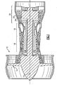
- the seal member 30 includes two circumferential sides 40 (one shown), a leading edge 42, a trailing edge 44, a radially outer side 46, and a radially inner side 48 that is adjacent to the hot gas flow 26.
- radial refers to the orientation of a particular side with reference to the engine centerline 12 of the gas turbine engine 20.
- the seal member 30 includes a substrate 50, and a gaspath layer 52 bonded to the radially inner side 48 of the substrate 50 and directly exposed to the hot gas flow 26.
- the gaspath layer 52 may be any thickness that is suitable for the intended use, such as up to 3mm thick. In some examples, the gaspath layer 52 may have a thickness up to about 1.5mm. In a further example, the gaspath layer 52 may be up to about 0.5mm thick, As will be explained below, the gaspath layer 52 facilitates resistance of thermal mechanical fatigue of the seal member 30.
- the seal member 30 may include internal cooling passages 53 for receiving a coolant (e.g., air from the compressor section 16).
- the gaspath layer 52 is formed of a metallic alloy and has a columnar microstructure 54 (shown schematically).
- the columnar microstructure 54 includes grains that are oriented with a long axis that is approximately perpendicular to the radially inner side 48.
- the heat of the hot gas flow 26 causes the seal member to thermally expand.
- the cooler radially outer surface does not expand as much as the radially inner surface that is exposed to the hot gas flow 26.
- the stiffness of the substrate and geometry of the seal member limit thermal expansion and contraction of the radially inner surface in the axial direction such that the radially inner surface is under compressive stress when temperatures are elevated.
- the radially inner surface may creep and relax while hot such that the radially inner surface is under tensile stress at cooler temperatures. After repeated cycles of heating and cooling, the stresses may cause deep microcracking at the radially inner surface.
- the gaspath layer 52 of the seal member 30 of the disclosed examples facilitates reduction of such thermal mechanical stresses. For instance, thermal expansion of the gaspath layer 52 occurs primarily in the radial direction and is uninhibited in circumferential and axial directions because of the columnar orientation 54. Therefore, the gaspath layer 52 is not subjected to the same limitation in thermal expansion and contraction in the axial direction as in a conventional seal member, and thereby reduces the amount of stress produced from thermal expansion and contraction.
- any microcracking that may occur in the gaspath layer 52 due to thermal mechanical fatigue would occur in the radial direction, approximately parallel to the long axes of the columnar grains, because of the orientation of the columnar microstructure 54 and thereby relieve at least a portion of the stress.
- the columnar microstructure 54 thereby may also permit some thermal-mechanical fatigue flexure and uneven thermal expansion of the seal member 30 without generating large stresses that may otherwise cause deep cracks through the substrate 50 in a conventional seal member.
- the use of the gaspath layer 52 having the columnar microstructure 54 to relieve stress allows the substrate 50 and the gaspath layer 52 to be made from materials that are suited for the functions of each.
- the substrate 50 in the disclosed example may primarily be a structural component, while the gaspath layer 52 may serve primarily for thermal mechanical fatigue resistance. Therefore, in a design stage, one may select materials suited to each particular function.
- the substrate 50 may be formed from a nickel-based alloy, such as a single crystal nickel alloy.
- the substrate 50 may be comprised of a single crystal of the nickel alloy.
- the gaspath layer 52 is formed of a different alloy, such as a cobalt-based alloy.
- the selected alloy may be better suited for forming the columnar microstructure 54, resisting thermal mechanical fatigue, or have other beneficial properties for exposure to the hot gas flow 26.
- cobalt-based alloy includes about 20wt% of chromium, about 15wt% of nickel, about 9wt% of tungsten, about 4.4wt% of aluminum, about 3wt% of tantalum, about 1wt% of hafnium, and a balance of cobalt. It is to be understood however, that other type of heat resistant alloys may be used and that the examples herein are not limited to any particular type of alloy.
- Figure 4 illustrates an example method 60 of manufacturing a gas turbine engine article, such as the seal member 30.
- the method 60 includes a step 62 of forming the gaspath layer 52, and a step 64 of bonding the gaspath layer 52 to the substrate 50.
- gaspath layer 52 there are various techniques for forming the gaspath layer 52. It is to be understood that there may be additional techniques for forming the gaspath layer 52 that may suit the particular needs of an application.
- forming the gaspath layer 52 includes a step 70 of laser consolidation.
- a powder having a composition that corresponds to the metallic alloy of the gaspath layer 52 is deposited onto the substrate 50 and consolidated in a known manner using a laser.
- the laser melts the powder and, upon solidification, the metallic alloy directionally solidifies to form the columnar microstructure 54.
- the substrate 50 may be used as a heat sink to remove heat during the laser consolidation process such that the liquid from the melted powder directionally solidifies.
- the radially outer side 46 may be cooled using water or air to control the cooling rate.
- forming the gaspath layer 52 includes a step 72 of casting a work piece from an alloy composition that corresponds to the metallic alloy selected for the gaspath layer 52.
- the alloy is directionally solidified in a known manner to produce the columnar microstructure 54.
- the work piece may then be cut or otherwise severed along a plane that is approximately perpendicular to the long axes of the columnar microstructure 54 into a separate piece that is then attached onto the substrate 50.
- the work piece could alternatively be formed by laser consolidating a powder as described above and cut or severed to provide the gaspath layer 52 as a separate piece that is then bonded to the substrate 50.
- the gaspath layer 52 may be brazed to the substrate 50. It is to be understood that this disclosure is not limited to brazing and that other techniques for bonding the gaspath layer 52 to the substrate 50 may be used.
Landscapes
- Chemical & Material Sciences (AREA)
- Engineering & Computer Science (AREA)
- Mechanical Engineering (AREA)
- Chemical Kinetics & Catalysis (AREA)
- Materials Engineering (AREA)
- Metallurgy (AREA)
- Organic Chemistry (AREA)
- General Engineering & Computer Science (AREA)
- Pressure Welding/Diffusion-Bonding (AREA)
- Turbine Rotor Nozzle Sealing (AREA)
Claims (15)
- Gasturbinenmaschinenkomponente (30) aufweisend:ein Substrat (50), das sich zwischen zwei umlaufenden Seiten (40), einer Vorderkante (42), einer Hinterkante (44), einer inneren Seite (48), um heißen Maschinenaustrittsgasen zu widerstehen und einer äußeren Seite (46) erstreckt; undeine Gasdurchgangslage (52), die mit der inneren Seite (48) des Substrats (50) verbunden ist, wobei die Gasdurchlasslage (50) eine metallische Legierung aufweist, die eine säulenartige Mikrostruktur aufweist; dadurch gekennzeichnet, dass:das Substrat (50) eine andere, unterschiedliche metallische Legierung als die metallische Legierung der Gasdurchlasslage (52) aufweist.
- Gasturbinenmaschinenkomponente nach Anspruch 1, wobei die metallische Legierung der Gasdurchlasslage (52) eine auf Cobalt basierende Legierung aufweist und die metallische Legierung des Substrats (50) eine auf Nickel basierende Legierung aufweist.
- Gasturbinenmaschinenkomponente nach Anspruch 1, wobei die metallische Legierung der Gasdurchlasslage (52) eine auf Cobalt basierende Legierung aufweist.
- Gasturbinenmaschinenkomponente nach einem der vorherigen Ansprüche, wobei die metallische Legierung der Gasdurchlasslage (52) zirka 20 Gew.% Chrom, zirka 15 Gew.% Nickel, zirka 9 Gew.% Wolfram, zirka 4,4 Gew.% Aluminium, zirka 3 Gew.% Tantal, zirka 1 Gew.% Hafnium und den Rest Cobalt aufweist.
- Gasturbinenmaschinenkomponente nach einem der vorherigen Ansprüche, wobei das Substrat (50) interne Kühlpassagen (53) aufweist.
- Gasturbinenmaschinenkomponente nach einem der vorherigen Ansprüche, wobei die Gasdurchlasslage (52) bis zu zirka 3 mm dick ist.
- Gasturbinenmaschine (10) aufweisend:einen Verdichterbereich (16);einen mit dem Verdichterbereich (16) in Fluidverbindung stehenden Verbrennungsraum (18); undeinen Turbinenbereich (20) stromabwärts von dem Verbrennungsraum (18), wobei der Turbinenbereich (20) eine Dichtung (30) aufweist, wobei die Dichtung eine Komponente nach einem der vorherigen Ansprüche ist.
- Verfahren zum Herstellen einer Gasturbinenmaschinenkomponente (30), aufweisend:Bilden einer Gasdurchlasslage (52), die eine metallische Legierung aufweist, die eine säulenartige Mikrostruktur hat; undVerbinden der Gasdurchlasslage (52) mit einer inneren Seite (48) eines Substrats (50), das sich zwischen zwei umlaufenden Seiten (40), einer Vorderkante (52), einer Hinterkante (44), der inneren Seite (48) zum Widerstehen von heißen Maschinenaustrittsgasen, und einer äußeren Seite (46) erstreckt; dadurch gekennzeichnet, dass:das Substrat (50) eine andere, unterschiedliche metallische Legierung als die metallische Legierung der Gasdurchlasslage (52) aufweist.
- Verfahren nach Anspruch 8, weiterhin aufweisend Bilden der Gasdurchlasslage (52) als ein getrenntes Stück von dem Substrat (50) und dann Verbinden des getrennten Teils mit der Innenseite (48) des Substrats (50).
- Verfahren nach einem der Ansprüche 8 oder 9, weiterhin aufweisend Bilden eines Arbeitsstücks aus der metallischen Legierung, die eine säulenartige Mikrostruktur aufweist, und Trennen des Arbeitsteils, um die Gasdurchlasslage (52) herzustellen.
- Verfahren nach Anspruch 10, aufweisend Trennen des Arbeitsstücks entlang einer Ebene, die ungefähr senkrecht zu der säulenartigen Mikrostruktur ist.
- Verfahren nach Anspruch 10 oder 11, aufweisend Bilden des Arbeitsstücks durch Verwenden von Laserverschmelzung oder Gießen.
- Verfahren nach einem der Ansprüche 8 bis 12, wobei das Verbinden Löten aufweist.
- Verfahren nach Anspruch 8, weiterhin aufweisend Anlagern eines Puders der metallischen Legierung und Laserverschmelzen des Puders, um die Gasdurchlasslage (52) zu bilden.
- Verfahren nach Anspruch 14, weiterhin aufweisend Beinhalten des Steuern/Regeln von Hitzeabfuhr während der Laserverschmelzung durch das Substrat (50), um die säulenartige Mikrostruktur zu bilden.
Applications Claiming Priority (1)
| Application Number | Priority Date | Filing Date | Title |
|---|---|---|---|
| US12/413,885 US8105014B2 (en) | 2009-03-30 | 2009-03-30 | Gas turbine engine article having columnar microstructure |
Publications (3)
| Publication Number | Publication Date |
|---|---|
| EP2236770A2 EP2236770A2 (de) | 2010-10-06 |
| EP2236770A3 EP2236770A3 (de) | 2013-11-20 |
| EP2236770B1 true EP2236770B1 (de) | 2015-02-18 |
Family
ID=42060975
Family Applications (1)
| Application Number | Title | Priority Date | Filing Date |
|---|---|---|---|
| EP10250330.7A Active EP2236770B1 (de) | 2009-03-30 | 2010-02-24 | Gasturbinenbauteil mit kristalliner Mikrostruktur |
Country Status (2)
| Country | Link |
|---|---|
| US (1) | US8105014B2 (de) |
| EP (1) | EP2236770B1 (de) |
Families Citing this family (5)
| Publication number | Priority date | Publication date | Assignee | Title |
|---|---|---|---|---|
| US8613590B2 (en) * | 2010-07-27 | 2013-12-24 | United Technologies Corporation | Blade outer air seal and repair method |
| US9827735B2 (en) * | 2012-03-09 | 2017-11-28 | United Technologies Corporation | Erosion resistant and hydrophobic article |
| EP3019313A4 (de) * | 2013-07-09 | 2017-04-05 | United Technologies Corporation | Keramikverkapselte thermopolymerstruktur oder träger mit metallplattierung |
| EP3019723A4 (de) | 2013-07-09 | 2017-05-10 | United Technologies Corporation | Beschichteter polymerverdichter |
| US12139794B2 (en) * | 2016-10-18 | 2024-11-12 | Purdue Research Foundation | Method of enhancing corrosion resistance of oxidizable materials and components made therefrom |
Family Cites Families (19)
| Publication number | Priority date | Publication date | Assignee | Title |
|---|---|---|---|---|
| US4069662A (en) * | 1975-12-05 | 1978-01-24 | United Technologies Corporation | Clearance control for gas turbine engine |
| US4321311A (en) * | 1980-01-07 | 1982-03-23 | United Technologies Corporation | Columnar grain ceramic thermal barrier coatings |
| US4422648A (en) * | 1982-06-17 | 1983-12-27 | United Technologies Corporation | Ceramic faced outer air seal for gas turbine engines |
| JPH0639885B2 (ja) * | 1988-03-14 | 1994-05-25 | 株式会社日立製作所 | ガスタービン用シュラウド及びガスタービン |
| JPH07503298A (ja) | 1992-11-24 | 1995-04-06 | ユナイテッド テクノロジーズ コーポレイション | タービン用の冷却可能なアウタエアシール装置 |
| DE69524353T2 (de) * | 1994-10-04 | 2002-08-08 | General Electric Co., Schenectady | Hochtemperatur-Schutzschicht |
| US6102656A (en) * | 1995-09-26 | 2000-08-15 | United Technologies Corporation | Segmented abradable ceramic coating |
| US6946208B2 (en) * | 1996-12-10 | 2005-09-20 | Siemens Westinghouse Power Corporation | Sinter resistant abradable thermal barrier coating |
| US6224963B1 (en) * | 1997-05-14 | 2001-05-01 | Alliedsignal Inc. | Laser segmented thick thermal barrier coatings for turbine shrouds |
| US5876860A (en) * | 1997-12-09 | 1999-03-02 | N.V. Interturbine | Thermal barrier coating ceramic structure |
| US6007880A (en) * | 1998-07-17 | 1999-12-28 | United Technologies Corporation | Method for generating a ceramic coating |
| US6187453B1 (en) * | 1998-07-17 | 2001-02-13 | United Technologies Corporation | Article having a durable ceramic coating |
| US6551372B1 (en) * | 1999-09-17 | 2003-04-22 | Rolls-Royce Corporation | High performance wrought powder metal articles and method of manufacture |
| US6703137B2 (en) * | 2001-08-02 | 2004-03-09 | Siemens Westinghouse Power Corporation | Segmented thermal barrier coating and method of manufacturing the same |
| US20050111966A1 (en) * | 2003-11-26 | 2005-05-26 | Metheny Alfred P. | Construction of static structures for gas turbine engines |
| DE102004002943B4 (de) | 2004-01-21 | 2007-07-19 | Mtu Aero Engines Gmbh | Schichtsystem für eine Rotor-/Statordichtung einer Strömungsmaschine |
| US7387488B2 (en) * | 2005-08-05 | 2008-06-17 | General Electric Company | Cooled turbine shroud |
| US7481098B2 (en) * | 2007-06-18 | 2009-01-27 | United Technologies Corporation | Method of determining depth of intergranular attack (IGA) for a metal part |
| US20110164963A1 (en) * | 2009-07-14 | 2011-07-07 | Thomas Alan Taylor | Coating system for clearance control in rotating machinery |
-
2009
- 2009-03-30 US US12/413,885 patent/US8105014B2/en active Active
-
2010
- 2010-02-24 EP EP10250330.7A patent/EP2236770B1/de active Active
Also Published As
| Publication number | Publication date |
|---|---|
| US20100247291A1 (en) | 2010-09-30 |
| US8105014B2 (en) | 2012-01-31 |
| EP2236770A3 (de) | 2013-11-20 |
| EP2236770A2 (de) | 2010-10-06 |
Similar Documents
| Publication | Publication Date | Title |
|---|---|---|
| US11313242B2 (en) | Thin seal for an engine | |
| EP2002030B1 (de) | Geschichtete wärmesperrenbeschichtung von hoher porosität und eine komponente davon | |
| EP3162917B1 (de) | Verfahren zur reparatur der wärmedämmschicht einer gasturbinenkomponente und resultierende komponenten | |
| US8449262B2 (en) | Nickel-based superalloys, turbine blades, and methods of improving or repairing turbine engine components | |
| US8535005B2 (en) | Blades, turbine blade assemblies, and methods of forming blades | |
| CN103796828B (zh) | 具有双层的MCrAlX金属层的层系统 | |
| US11181002B2 (en) | Turbine systems with sealing components | |
| CN101618610A (zh) | 具有两层陶瓷层的陶瓷热障涂层系统 | |
| EP2236770B1 (de) | Gasturbinenbauteil mit kristalliner Mikrostruktur | |
| JP2013530309A (ja) | 合金、保護層、及び部品 | |
| CN102301019A (zh) | 合金、保护层和部件 | |
| US11555419B2 (en) | Cost effective manufacturing method for GSAC incorporating a stamped preform | |
| US8858873B2 (en) | Nickel-based superalloys for use on turbine blades | |
| US20140003937A1 (en) | Component and a method of cooling a component | |
| CN106150564B (zh) | 燃气涡轮机的可磨耗唇部 | |
| JPH11132465A (ja) | タービン燃焼器部品用保護皮膜 | |
| CN103298607A (zh) | 合金、保护层和构件 | |
| CN103797141A (zh) | 合金、保护层和构件 | |
| CN101133173A (zh) | 合金,防止构件高温腐蚀和/或氧化的保护层及构件 | |
| KR101597924B1 (ko) | 2겹 금속층을 포함하는 층 시스템 | |
| US20240229654A1 (en) | Wear resistant article and method of making | |
| US20140255652A1 (en) | Surface having specially formed recesses and component | |
| EP4397788A1 (de) | Verschleissfester artikel und herstellungsverfahren | |
| CN103282197A (zh) | 合金、保护层和构件 | |
| US20070295471A1 (en) | Casting Process and Cast Component |
Legal Events
| Date | Code | Title | Description |
|---|---|---|---|
| PUAI | Public reference made under article 153(3) epc to a published international application that has entered the european phase |
Free format text: ORIGINAL CODE: 0009012 |
|
| AK | Designated contracting states |
Kind code of ref document: A2 Designated state(s): AT BE BG CH CY CZ DE DK EE ES FI FR GB GR HR HU IE IS IT LI LT LU LV MC MK MT NL NO PL PT RO SE SI SK SM TR |
|
| AX | Request for extension of the european patent |
Extension state: AL BA RS |
|
| PUAL | Search report despatched |
Free format text: ORIGINAL CODE: 0009013 |
|
| AK | Designated contracting states |
Kind code of ref document: A3 Designated state(s): AT BE BG CH CY CZ DE DK EE ES FI FR GB GR HR HU IE IS IT LI LT LU LV MC MK MT NL NO PL PT RO SE SI SK SM TR |
|
| AX | Request for extension of the european patent |
Extension state: AL BA RS |
|
| RIC1 | Information provided on ipc code assigned before grant |
Ipc: C23C 30/00 20060101ALI20131016BHEP Ipc: F01D 11/08 20060101AFI20131016BHEP |
|
| 17P | Request for examination filed |
Effective date: 20140520 |
|
| RBV | Designated contracting states (corrected) |
Designated state(s): AT BE BG CH CY CZ DE DK EE ES FI FR GB GR HR HU IE IS IT LI LT LU LV MC MK MT NL NO PL PT RO SE SI SK SM TR |
|
| GRAP | Despatch of communication of intention to grant a patent |
Free format text: ORIGINAL CODE: EPIDOSNIGR1 |
|
| RIC1 | Information provided on ipc code assigned before grant |
Ipc: F01D 11/08 20060101AFI20140730BHEP Ipc: C23C 30/00 20060101ALI20140730BHEP |
|
| INTG | Intention to grant announced |
Effective date: 20140813 |
|
| GRAS | Grant fee paid |
Free format text: ORIGINAL CODE: EPIDOSNIGR3 |
|
| GRAA | (expected) grant |
Free format text: ORIGINAL CODE: 0009210 |
|
| AK | Designated contracting states |
Kind code of ref document: B1 Designated state(s): AT BE BG CH CY CZ DE DK EE ES FI FR GB GR HR HU IE IS IT LI LT LU LV MC MK MT NL NO PL PT RO SE SI SK SM TR |
|
| REG | Reference to a national code |
Ref country code: GB Ref legal event code: FG4D |
|
| REG | Reference to a national code |
Ref country code: CH Ref legal event code: EP |
|
| REG | Reference to a national code |
Ref country code: AT Ref legal event code: REF Ref document number: 710763 Country of ref document: AT Kind code of ref document: T Effective date: 20150315 |
|
| REG | Reference to a national code |
Ref country code: IE Ref legal event code: FG4D |
|
| REG | Reference to a national code |
Ref country code: DE Ref legal event code: R096 Ref document number: 602010022303 Country of ref document: DE Effective date: 20150402 |
|
| PG25 | Lapsed in a contracting state [announced via postgrant information from national office to epo] |
Ref country code: BE Free format text: LAPSE BECAUSE OF NON-PAYMENT OF DUE FEES Effective date: 20150228 |
|
| REG | Reference to a national code |
Ref country code: NL Ref legal event code: VDEP Effective date: 20150218 |
|
| REG | Reference to a national code |
Ref country code: AT Ref legal event code: MK05 Ref document number: 710763 Country of ref document: AT Kind code of ref document: T Effective date: 20150218 |
|
| REG | Reference to a national code |
Ref country code: LT Ref legal event code: MG4D |
|
| PG25 | Lapsed in a contracting state [announced via postgrant information from national office to epo] |
Ref country code: LT Free format text: LAPSE BECAUSE OF FAILURE TO SUBMIT A TRANSLATION OF THE DESCRIPTION OR TO PAY THE FEE WITHIN THE PRESCRIBED TIME-LIMIT Effective date: 20150218 Ref country code: NO Free format text: LAPSE BECAUSE OF FAILURE TO SUBMIT A TRANSLATION OF THE DESCRIPTION OR TO PAY THE FEE WITHIN THE PRESCRIBED TIME-LIMIT Effective date: 20150518 Ref country code: ES Free format text: LAPSE BECAUSE OF FAILURE TO SUBMIT A TRANSLATION OF THE DESCRIPTION OR TO PAY THE FEE WITHIN THE PRESCRIBED TIME-LIMIT Effective date: 20150218 Ref country code: HR Free format text: LAPSE BECAUSE OF FAILURE TO SUBMIT A TRANSLATION OF THE DESCRIPTION OR TO PAY THE FEE WITHIN THE PRESCRIBED TIME-LIMIT Effective date: 20150218 Ref country code: FI Free format text: LAPSE BECAUSE OF FAILURE TO SUBMIT A TRANSLATION OF THE DESCRIPTION OR TO PAY THE FEE WITHIN THE PRESCRIBED TIME-LIMIT Effective date: 20150218 Ref country code: SE Free format text: LAPSE BECAUSE OF FAILURE TO SUBMIT A TRANSLATION OF THE DESCRIPTION OR TO PAY THE FEE WITHIN THE PRESCRIBED TIME-LIMIT Effective date: 20150218 |
|
| PG25 | Lapsed in a contracting state [announced via postgrant information from national office to epo] |
Ref country code: NL Free format text: LAPSE BECAUSE OF FAILURE TO SUBMIT A TRANSLATION OF THE DESCRIPTION OR TO PAY THE FEE WITHIN THE PRESCRIBED TIME-LIMIT Effective date: 20150218 Ref country code: LV Free format text: LAPSE BECAUSE OF FAILURE TO SUBMIT A TRANSLATION OF THE DESCRIPTION OR TO PAY THE FEE WITHIN THE PRESCRIBED TIME-LIMIT Effective date: 20150218 Ref country code: IS Free format text: LAPSE BECAUSE OF FAILURE TO SUBMIT A TRANSLATION OF THE DESCRIPTION OR TO PAY THE FEE WITHIN THE PRESCRIBED TIME-LIMIT Effective date: 20150618 Ref country code: GR Free format text: LAPSE BECAUSE OF FAILURE TO SUBMIT A TRANSLATION OF THE DESCRIPTION OR TO PAY THE FEE WITHIN THE PRESCRIBED TIME-LIMIT Effective date: 20150519 Ref country code: AT Free format text: LAPSE BECAUSE OF FAILURE TO SUBMIT A TRANSLATION OF THE DESCRIPTION OR TO PAY THE FEE WITHIN THE PRESCRIBED TIME-LIMIT Effective date: 20150218 |
|
| REG | Reference to a national code |
Ref country code: CH Ref legal event code: PL |
|
| PG25 | Lapsed in a contracting state [announced via postgrant information from national office to epo] |
Ref country code: EE Free format text: LAPSE BECAUSE OF FAILURE TO SUBMIT A TRANSLATION OF THE DESCRIPTION OR TO PAY THE FEE WITHIN THE PRESCRIBED TIME-LIMIT Effective date: 20150218 Ref country code: CH Free format text: LAPSE BECAUSE OF NON-PAYMENT OF DUE FEES Effective date: 20150228 Ref country code: DK Free format text: LAPSE BECAUSE OF FAILURE TO SUBMIT A TRANSLATION OF THE DESCRIPTION OR TO PAY THE FEE WITHIN THE PRESCRIBED TIME-LIMIT Effective date: 20150218 Ref country code: SK Free format text: LAPSE BECAUSE OF FAILURE TO SUBMIT A TRANSLATION OF THE DESCRIPTION OR TO PAY THE FEE WITHIN THE PRESCRIBED TIME-LIMIT Effective date: 20150218 Ref country code: LI Free format text: LAPSE BECAUSE OF NON-PAYMENT OF DUE FEES Effective date: 20150228 Ref country code: CZ Free format text: LAPSE BECAUSE OF FAILURE TO SUBMIT A TRANSLATION OF THE DESCRIPTION OR TO PAY THE FEE WITHIN THE PRESCRIBED TIME-LIMIT Effective date: 20150218 Ref country code: RO Free format text: LAPSE BECAUSE OF FAILURE TO SUBMIT A TRANSLATION OF THE DESCRIPTION OR TO PAY THE FEE WITHIN THE PRESCRIBED TIME-LIMIT Effective date: 20150218 |
|
| REG | Reference to a national code |
Ref country code: IE Ref legal event code: MM4A |
|
| REG | Reference to a national code |
Ref country code: DE Ref legal event code: R097 Ref document number: 602010022303 Country of ref document: DE |
|
| PG25 | Lapsed in a contracting state [announced via postgrant information from national office to epo] |
Ref country code: MC Free format text: LAPSE BECAUSE OF FAILURE TO SUBMIT A TRANSLATION OF THE DESCRIPTION OR TO PAY THE FEE WITHIN THE PRESCRIBED TIME-LIMIT Effective date: 20150218 Ref country code: PL Free format text: LAPSE BECAUSE OF FAILURE TO SUBMIT A TRANSLATION OF THE DESCRIPTION OR TO PAY THE FEE WITHIN THE PRESCRIBED TIME-LIMIT Effective date: 20150218 |
|
| PLBE | No opposition filed within time limit |
Free format text: ORIGINAL CODE: 0009261 |
|
| STAA | Information on the status of an ep patent application or granted ep patent |
Free format text: STATUS: NO OPPOSITION FILED WITHIN TIME LIMIT |
|
| PG25 | Lapsed in a contracting state [announced via postgrant information from national office to epo] |
Ref country code: IT Free format text: LAPSE BECAUSE OF FAILURE TO SUBMIT A TRANSLATION OF THE DESCRIPTION OR TO PAY THE FEE WITHIN THE PRESCRIBED TIME-LIMIT Effective date: 20150218 |
|
| REG | Reference to a national code |
Ref country code: FR Ref legal event code: PLFP Year of fee payment: 7 |
|
| 26N | No opposition filed |
Effective date: 20151119 |
|
| PG25 | Lapsed in a contracting state [announced via postgrant information from national office to epo] |
Ref country code: IE Free format text: LAPSE BECAUSE OF NON-PAYMENT OF DUE FEES Effective date: 20150224 |
|
| PG25 | Lapsed in a contracting state [announced via postgrant information from national office to epo] |
Ref country code: SI Free format text: LAPSE BECAUSE OF FAILURE TO SUBMIT A TRANSLATION OF THE DESCRIPTION OR TO PAY THE FEE WITHIN THE PRESCRIBED TIME-LIMIT Effective date: 20150218 |
|
| PG25 | Lapsed in a contracting state [announced via postgrant information from national office to epo] |
Ref country code: BE Free format text: LAPSE BECAUSE OF FAILURE TO SUBMIT A TRANSLATION OF THE DESCRIPTION OR TO PAY THE FEE WITHIN THE PRESCRIBED TIME-LIMIT Effective date: 20150218 |
|
| PG25 | Lapsed in a contracting state [announced via postgrant information from national office to epo] |
Ref country code: MT Free format text: LAPSE BECAUSE OF FAILURE TO SUBMIT A TRANSLATION OF THE DESCRIPTION OR TO PAY THE FEE WITHIN THE PRESCRIBED TIME-LIMIT Effective date: 20150218 |
|
| REG | Reference to a national code |
Ref country code: FR Ref legal event code: PLFP Year of fee payment: 8 |
|
| REG | Reference to a national code |
Ref country code: FR Ref legal event code: CA Effective date: 20170324 |
|
| PG25 | Lapsed in a contracting state [announced via postgrant information from national office to epo] |
Ref country code: SM Free format text: LAPSE BECAUSE OF FAILURE TO SUBMIT A TRANSLATION OF THE DESCRIPTION OR TO PAY THE FEE WITHIN THE PRESCRIBED TIME-LIMIT Effective date: 20150218 Ref country code: HU Free format text: LAPSE BECAUSE OF FAILURE TO SUBMIT A TRANSLATION OF THE DESCRIPTION OR TO PAY THE FEE WITHIN THE PRESCRIBED TIME-LIMIT; INVALID AB INITIO Effective date: 20100224 Ref country code: BG Free format text: LAPSE BECAUSE OF FAILURE TO SUBMIT A TRANSLATION OF THE DESCRIPTION OR TO PAY THE FEE WITHIN THE PRESCRIBED TIME-LIMIT Effective date: 20150218 |
|
| PG25 | Lapsed in a contracting state [announced via postgrant information from national office to epo] |
Ref country code: CY Free format text: LAPSE BECAUSE OF FAILURE TO SUBMIT A TRANSLATION OF THE DESCRIPTION OR TO PAY THE FEE WITHIN THE PRESCRIBED TIME-LIMIT Effective date: 20150218 |
|
| REG | Reference to a national code |
Ref country code: DE Ref legal event code: R082 Ref document number: 602010022303 Country of ref document: DE Representative=s name: SCHMITT-NILSON SCHRAUD WAIBEL WOHLFROM PATENTA, DE |
|
| REG | Reference to a national code |
Ref country code: DE Ref legal event code: R082 Ref document number: 602010022303 Country of ref document: DE Representative=s name: SCHMITT-NILSON SCHRAUD WAIBEL WOHLFROM PATENTA, DE Ref country code: DE Ref legal event code: R081 Ref document number: 602010022303 Country of ref document: DE Owner name: UNITED TECHNOLOGIES CORP. (N.D.GES.D. STAATES , US Free format text: FORMER OWNER: UNITED TECHNOLOGIES CORP., HARTFORD, CONN., US |
|
| PG25 | Lapsed in a contracting state [announced via postgrant information from national office to epo] |
Ref country code: PT Free format text: LAPSE BECAUSE OF FAILURE TO SUBMIT A TRANSLATION OF THE DESCRIPTION OR TO PAY THE FEE WITHIN THE PRESCRIBED TIME-LIMIT Effective date: 20150618 |
|
| PG25 | Lapsed in a contracting state [announced via postgrant information from national office to epo] |
Ref country code: TR Free format text: LAPSE BECAUSE OF FAILURE TO SUBMIT A TRANSLATION OF THE DESCRIPTION OR TO PAY THE FEE WITHIN THE PRESCRIBED TIME-LIMIT Effective date: 20150218 |
|
| PG25 | Lapsed in a contracting state [announced via postgrant information from national office to epo] |
Ref country code: LU Free format text: LAPSE BECAUSE OF NON-PAYMENT OF DUE FEES Effective date: 20150224 |
|
| REG | Reference to a national code |
Ref country code: FR Ref legal event code: PLFP Year of fee payment: 9 |
|
| PG25 | Lapsed in a contracting state [announced via postgrant information from national office to epo] |
Ref country code: MK Free format text: LAPSE BECAUSE OF FAILURE TO SUBMIT A TRANSLATION OF THE DESCRIPTION OR TO PAY THE FEE WITHIN THE PRESCRIBED TIME-LIMIT Effective date: 20150218 |
|
| REG | Reference to a national code |
Ref country code: DE Ref legal event code: R081 Ref document number: 602010022303 Country of ref document: DE Owner name: RAYTHEON TECHNOLOGIES CORPORATION (N.D.GES.D.S, US Free format text: FORMER OWNER: UNITED TECHNOLOGIES CORP. (N.D.GES.D. STAATES DELAWARE), FARMINGTON, CONN., US Ref country code: DE Ref legal event code: R081 Ref document number: 602010022303 Country of ref document: DE Owner name: RTX CORPORATION (N.D.GES.D. STAATES DELAWARE),, US Free format text: FORMER OWNER: UNITED TECHNOLOGIES CORP. (N.D.GES.D. STAATES DELAWARE), FARMINGTON, CONN., US |
|
| P01 | Opt-out of the competence of the unified patent court (upc) registered |
Effective date: 20230519 |
|
| PGFP | Annual fee paid to national office [announced via postgrant information from national office to epo] |
Ref country code: DE Payment date: 20250122 Year of fee payment: 16 |
|
| PGFP | Annual fee paid to national office [announced via postgrant information from national office to epo] |
Ref country code: FR Payment date: 20250121 Year of fee payment: 16 |
|
| PGFP | Annual fee paid to national office [announced via postgrant information from national office to epo] |
Ref country code: GB Payment date: 20250123 Year of fee payment: 16 |
|
| REG | Reference to a national code |
Ref country code: DE Ref legal event code: R081 Ref document number: 602010022303 Country of ref document: DE Owner name: RTX CORPORATION (N.D.GES.D. STAATES DELAWARE),, US Free format text: FORMER OWNER: RAYTHEON TECHNOLOGIES CORPORATION (N.D.GES.D.STAATES DELAWARE), ARLINGTON, VA, US |