EP2236772B1 - Moteur à turbine à gaz avec dispositif actif de contrôle de jeu en bout d'aube et procédé d'exploitation associé - Google Patents
Moteur à turbine à gaz avec dispositif actif de contrôle de jeu en bout d'aube et procédé d'exploitation associé Download PDFInfo
- Publication number
- EP2236772B1 EP2236772B1 EP10250560.9A EP10250560A EP2236772B1 EP 2236772 B1 EP2236772 B1 EP 2236772B1 EP 10250560 A EP10250560 A EP 10250560A EP 2236772 B1 EP2236772 B1 EP 2236772B1
- Authority
- EP
- European Patent Office
- Prior art keywords
- bypass air
- annular
- engine
- core
- case
- Prior art date
- Legal status (The legal status is an assumption and is not a legal conclusion. Google has not performed a legal analysis and makes no representation as to the accuracy of the status listed.)
- Active
Links
Images

Classifications
-
- F—MECHANICAL ENGINEERING; LIGHTING; HEATING; WEAPONS; BLASTING
- F01—MACHINES OR ENGINES IN GENERAL; ENGINE PLANTS IN GENERAL; STEAM ENGINES
- F01D—NON-POSITIVE DISPLACEMENT MACHINES OR ENGINES, e.g. STEAM TURBINES
- F01D11/00—Preventing or minimising internal leakage of working-fluid, e.g. between stages
- F01D11/08—Preventing or minimising internal leakage of working-fluid, e.g. between stages for sealing space between rotor blade tips and stator
- F01D11/14—Adjusting or regulating tip-clearance, i.e. distance between rotor-blade tips and stator casing
- F01D11/20—Actively adjusting tip-clearance
- F01D11/24—Actively adjusting tip-clearance by selectively cooling-heating stator or rotor components
-
- F—MECHANICAL ENGINEERING; LIGHTING; HEATING; WEAPONS; BLASTING
- F01—MACHINES OR ENGINES IN GENERAL; ENGINE PLANTS IN GENERAL; STEAM ENGINES
- F01D—NON-POSITIVE DISPLACEMENT MACHINES OR ENGINES, e.g. STEAM TURBINES
- F01D25/00—Component parts, details, or accessories, not provided for in, or of interest apart from, other groups
- F01D25/08—Cooling; Heating; Heat-insulation
- F01D25/12—Cooling
-
- F—MECHANICAL ENGINEERING; LIGHTING; HEATING; WEAPONS; BLASTING
- F02—COMBUSTION ENGINES; HOT-GAS OR COMBUSTION-PRODUCT ENGINE PLANTS
- F02C—GAS-TURBINE PLANTS; AIR INTAKES FOR JET-PROPULSION PLANTS; CONTROLLING FUEL SUPPLY IN AIR-BREATHING JET-PROPULSION PLANTS
- F02C6/00—Plural gas-turbine plants; Combinations of gas-turbine plants with other apparatus; Adaptations of gas-turbine plants for special use
- F02C6/04—Gas-turbine plants providing heated or pressurised working fluid for other apparatus, e.g. without mechanical power output
- F02C6/06—Gas-turbine plants providing heated or pressurised working fluid for other apparatus, e.g. without mechanical power output providing compressed gas
- F02C6/08—Gas-turbine plants providing heated or pressurised working fluid for other apparatus, e.g. without mechanical power output providing compressed gas the gas being bled from the gas-turbine compressor
-
- F—MECHANICAL ENGINEERING; LIGHTING; HEATING; WEAPONS; BLASTING
- F02—COMBUSTION ENGINES; HOT-GAS OR COMBUSTION-PRODUCT ENGINE PLANTS
- F02K—JET-PROPULSION PLANTS
- F02K3/00—Plants including a gas turbine driving a compressor or a ducted fan
- F02K3/02—Plants including a gas turbine driving a compressor or a ducted fan in which part of the working fluid by-passes the turbine and combustion chamber
-
- F—MECHANICAL ENGINEERING; LIGHTING; HEATING; WEAPONS; BLASTING
- F05—INDEXING SCHEMES RELATING TO ENGINES OR PUMPS IN VARIOUS SUBCLASSES OF CLASSES F01-F04
- F05D—INDEXING SCHEME FOR ASPECTS RELATING TO NON-POSITIVE-DISPLACEMENT MACHINES OR ENGINES, GAS-TURBINES OR JET-PROPULSION PLANTS
- F05D2260/00—Function
- F05D2260/20—Heat transfer, e.g. cooling
- F05D2260/201—Heat transfer, e.g. cooling by impingement of a fluid
-
- Y—GENERAL TAGGING OF NEW TECHNOLOGICAL DEVELOPMENTS; GENERAL TAGGING OF CROSS-SECTIONAL TECHNOLOGIES SPANNING OVER SEVERAL SECTIONS OF THE IPC; TECHNICAL SUBJECTS COVERED BY FORMER USPC CROSS-REFERENCE ART COLLECTIONS [XRACs] AND DIGESTS
- Y02—TECHNOLOGIES OR APPLICATIONS FOR MITIGATION OR ADAPTATION AGAINST CLIMATE CHANGE
- Y02T—CLIMATE CHANGE MITIGATION TECHNOLOGIES RELATED TO TRANSPORTATION
- Y02T50/00—Aeronautics or air transport
- Y02T50/60—Efficient propulsion technologies, e.g. for aircraft
Definitions
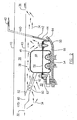
- the sealed annular cavity 66 which is situated within but isolated from the pressurized core compartment 30, provides a significant pressure drop ⁇ P to the pressure within the manifold 46, which is substantially close to the pressure of the bypass air flow in the annular bypass air duct 28.
- This pressure drop or pressure differential ⁇ P helps the discharge of the second portion 42 of the bypass air flow from the manifold 46 and impingement of same on the outer surface of the turbine case 50.
Landscapes
- Engineering & Computer Science (AREA)
- Mechanical Engineering (AREA)
- General Engineering & Computer Science (AREA)
- Chemical & Material Sciences (AREA)
- Combustion & Propulsion (AREA)
- Turbine Rotor Nozzle Sealing (AREA)
- Structures Of Non-Positive Displacement Pumps (AREA)
Claims (15)
- Moteur à turbine à gaz d'un turboréacteur à double flux d'aéronef comprenant :un boîtier extérieur annulaire (10) entourant un ensemble de ventilateur (14) ;un boîtier central annulaire (13) positionné dans le boîtier extérieur (10) et logeant un ensemble de compresseur (16), un ensemble de générateur de gaz de combustion (26) et un ensemble de turbine (18 ; 24), les boîtiers extérieur et central annulaires (10 ; 13) définissant un conduit d'air de dérivation annulaire (28) entre eux pour diriger le passage au travers de celui-ci d'un flux d'air de dérivation entraîné par l'ensemble de ventilateur (14) ;un compartiment central (30) configuré dans le boîtier central annulaire (13), le compartiment central (30) présentant une entrée (32) définie dans le boîtier central annulaire (13) pour l'introduction d'une première partie (34) du flux d'air de dérivation dans le compartiment central (30) pour refroidir un nombre de composants de moteur situés dans le compartiment central (30) et présentant une sortie (36) définie dans le boîtier central annulaire (13) en aval de l'entrée (32), le compartiment central (30) étant étanche pour permettre à la première partie (34) du flux d'air de dérivation d'être évacuée seulement par la sortie (36) et de revenir au conduit d'air de dérivation annulaire (28) ; etun appareil de commande active du jeu des extrémités (ATCC) (38) situé dans le compartiment central étanche (30), l'appareil ATCC (38) présentant une entrée (40) définie dans le boîtier central annulaire (13) pour l'introduction d'une seconde partie (42) du flux d'air de dérivation dans l'appareil ATCC (38) et présentant un passage de ventilation (44) en communication fluidique avec l'atmosphère, caractérisé en ce que l'appareil ATCC (38) est étanche pour empêcher le mélange de la seconde partie (42) du flux d'air de dérivation avec la première partie (34) du flux d'air de dérivation.
- Moteur selon la revendication 1, dans lequel l'appareil ATCC (38) comprend un manifold annulaire (46) autour de l'ensemble de turbine (18 ; 24) pour l'évacuation de la seconde partie (42) du flux d'air de dérivation pour refroidir l'ensemble de turbine (18 ; 24), réduisant par là-même des jeux entre des composants de turbine.
- Moteur selon la revendication 2, dans lequel l'appareil ATCC (38) comprend une cavité annulaire étanche définie radialement entre le manifold annulaire (46) et un boîtier de turbine (50) à refroidir par la seconde partie (42) du flux d'air de dérivation, la cavité annulaire étanche (66) étant empêchée de communiquer fluidiquement avec le compartiment central (30).
- Moteur selon la revendication 3, dans lequel le manifold annulaire (46) comprend une pluralité de trous (56) définis dans le manifold annulaire (46) pour permettre à la seconde partie (42) du flux d'air de dérivation de former une pluralité de courants d'air évacués du manifold annulaire (42) et heurtant une surface extérieure du boîtier de turbine (50).
- Moteur selon la revendication 3 ou 4, dans lequel le passage de ventilation (44) est en communication fluidique avec la cavité annulaire étanche (66).
- Moteur selon la revendication 5, dans lequel le passage de ventilation (44) comprend une sortie évacuant la seconde partie (42) du flux d'air de dérivation dans l'atmosphère dans une direction arrière.
- Moteur selon l'une quelconque des revendications 3 à 6, dans lequel l'appareil ATCC (38) comprend des dispositifs de montage pour le montage du manifold annulaire (46) sur le boîtier de turbine (50), les dispositifs de montage formant des parois étanches annulaires avant et arrière respectives (62, 64) s'étendant radialement entre le manifold annulaire (46) et le boîtier de turbine (50) pour définir par là-même la cavité annulaire étanche (66).
- Moteur selon l'une quelconque des revendications 2 à 7, dans lequel l'appareil ATCC (38) comprend un passage d'entrée (52) s'étendant de l'entrée (40) de l'appareil ATCC (38) au manifold annulaire (46).
- Moteur selon la revendication 8, dans lequel l'appareil ATCC (38) comprend une soupape (60) reliée dans le passage d'entrée (52) pour la commande d'un débit de la seconde partie (42) du flux d'air de dérivation, commandant par là-même lesdits jeux entre des composants de turbine.
- Moteur selon la revendication 9, dans lequel le passage de ventilation (44) est relié à la paroi étanche annulaire arrière (64).
- Moteur selon l'une quelconque des revendications précédentes, dans lequel les entrées respectives (32, 40) du compartiment central (30) et de l'appareil ATCC (38) sont définies par des première et seconde ouvertures dans le boîtier central annulaire (13), sont exemptes de composants s'étendant sensiblement radialement dans le conduit d'air de dérivation annulaire (28).
- Procédé d'utilisation d'air de dérivation d'un moteur de turbine à gaz de turboréacteur à double flux pour refroidir le moteur tout en réduisant des pertes de poussée d'air de dérivation, le procédé comprenant les étapes suivantes :a) la direction d'une première partie (34) d'air de dérivation d'un conduit d'air de dérivation (28) du moteur dans un compartiment central (30) d'un boîtier central (13) du moteur pour refroidir un nombre de composants de moteur dans le compartiment central (30) de manière à maintenir sensiblement une pression d'air de la première partie d'air de dérivation et la réinjection suivante de la première partie (34) d'air de dérivation dans un flux d'air de dérivation principal passant par le conduit d'air de dérivation (28) ;b) la direction d'une seconde partie (42) d'air de dérivation du conduit d'air de dérivation (28) pour passer par un appareil de commande active du jeu des extrémités (ATCC) (38) dans le compartiment central (30) pour refroidir un boîtier de turbine annulaire (50) et la ventilation suivante de la seconde partie (42) d'air de dérivation vers l'atmosphère ; caractérisé par l'étape suivantec) l'isolation de la seconde partie (42) d'air de dérivation par rapport à la première partie d'air de dérivation (34) pour empêcher le mélange l'une avec l'autre.
- Procédé selon la revendication 12, dans lequel l'étape (b) comprend une autre étape consistant à amener la seconde partie (42) d'air de dérivation à former une pluralité de courants d'air (56) s'évacuant d'un plénum (48) et heurtant une surface extérieure d'un boîtier de turbine annulaire (50).
- Procédé selon la revendication 13, dans lequel l'action de heurter est réalisée dans une cavité étanche (66) isolée du compartiment central (30), la cavité étanche (66) étant en communication fluidique avec l'atmosphère pour créer une chute de pression dans la cavité étanche (66) par rapport à une pression dans le plénum (48), résultant par là-même en ladite action d'heurter.
- Procédé selon la revendication 14, dans lequel la cavité étanche (66) est définie radialement entre le plénum (48) et le boîtier de turbine (50).
Applications Claiming Priority (1)
| Application Number | Priority Date | Filing Date | Title |
|---|---|---|---|
| US12/411,495 US8092146B2 (en) | 2009-03-26 | 2009-03-26 | Active tip clearance control arrangement for gas turbine engine |
Publications (3)
| Publication Number | Publication Date |
|---|---|
| EP2236772A2 EP2236772A2 (fr) | 2010-10-06 |
| EP2236772A3 EP2236772A3 (fr) | 2014-07-23 |
| EP2236772B1 true EP2236772B1 (fr) | 2015-09-30 |
Family
ID=42167690
Family Applications (1)
| Application Number | Title | Priority Date | Filing Date |
|---|---|---|---|
| EP10250560.9A Active EP2236772B1 (fr) | 2009-03-26 | 2010-03-24 | Moteur à turbine à gaz avec dispositif actif de contrôle de jeu en bout d'aube et procédé d'exploitation associé |
Country Status (3)
| Country | Link |
|---|---|
| US (1) | US8092146B2 (fr) |
| EP (1) | EP2236772B1 (fr) |
| CA (1) | CA2696623C (fr) |
Families Citing this family (54)
| Publication number | Priority date | Publication date | Assignee | Title |
|---|---|---|---|---|
| US7491029B2 (en) | 2005-10-14 | 2009-02-17 | United Technologies Corporation | Active clearance control system for gas turbine engines |
| GB0906059D0 (en) * | 2009-04-08 | 2009-05-20 | Rolls Royce Plc | Thermal control system for turbines |
| GB201104043D0 (en) * | 2011-03-10 | 2011-04-20 | Rolls Royce Plc | A gas turbine engine |
| US8826668B2 (en) * | 2011-08-02 | 2014-09-09 | Siemens Energy, Inc. | Two stage serial impingement cooling for isogrid structures |
| US9475584B2 (en) * | 2011-09-02 | 2016-10-25 | Honeywell International Inc. | Cabin pressure control system thrust recovery outflow valve and method that enable ram air recovery |
| US9039346B2 (en) | 2011-10-17 | 2015-05-26 | General Electric Company | Rotor support thermal control system |
| US9157331B2 (en) * | 2011-12-08 | 2015-10-13 | Siemens Aktiengesellschaft | Radial active clearance control for a gas turbine engine |
| US9316111B2 (en) * | 2011-12-15 | 2016-04-19 | Pratt & Whitney Canada Corp. | Active turbine tip clearance control system |
| US9115595B2 (en) * | 2012-04-09 | 2015-08-25 | General Electric Company | Clearance control system for a gas turbine |
| US9719372B2 (en) * | 2012-05-01 | 2017-08-01 | General Electric Company | Gas turbomachine including a counter-flow cooling system and method |
| ITTO20120519A1 (it) | 2012-06-14 | 2013-12-15 | Avio Spa | Turbina a gas per motori aeronautici |
| US9341074B2 (en) | 2012-07-25 | 2016-05-17 | General Electric Company | Active clearance control manifold system |
| US10557368B2 (en) | 2013-04-12 | 2020-02-11 | United Technologies Corporation | Gas turbine engine rapid response clearance control system with variable volume turbine case |
| US9266618B2 (en) * | 2013-11-18 | 2016-02-23 | Honeywell International Inc. | Gas turbine engine turbine blade tip active clearance control system and method |
| US10330012B2 (en) * | 2014-02-04 | 2019-06-25 | United Technologies Corporation | Brackets for gas turbine engine components |
| US10443429B2 (en) * | 2014-02-13 | 2019-10-15 | United Technologies Corporation | Gas turbine nacelle ventilation manifold having a circumferential varying cross-sectional area |
| US9593589B2 (en) | 2014-02-28 | 2017-03-14 | General Electric Company | System and method for thrust bearing actuation to actively control clearance in a turbo machine |
| EP2918787B1 (fr) * | 2014-03-12 | 2017-10-18 | Rolls-Royce Deutschland Ltd & Co KG | Système de guidage d'écoulement et moteur à combustion rotatif |
| WO2016025054A2 (fr) * | 2014-05-29 | 2016-02-18 | General Electric Company | Éléments de turbine à gaz ayant des caractéristiques de refroidissement |
| US9874105B2 (en) * | 2015-01-26 | 2018-01-23 | United Technologies Corporation | Active clearance control systems |
| US9938874B2 (en) * | 2015-06-29 | 2018-04-10 | General Electric Company | Power generation system exhaust cooling |
| US10060316B2 (en) | 2015-06-29 | 2018-08-28 | General Electric Company | Power generation system exhaust cooling |
| US10030558B2 (en) | 2015-06-29 | 2018-07-24 | General Electric Company | Power generation system exhaust cooling |
| US10087801B2 (en) | 2015-06-29 | 2018-10-02 | General Electric Company | Power generation system exhaust cooling |
| US10215070B2 (en) | 2015-06-29 | 2019-02-26 | General Electric Company | Power generation system exhaust cooling |
| US9835092B2 (en) | 2015-06-30 | 2017-12-05 | United Technologies Corporation | Seals for gas turbine engine nacelle cowlings |
| US10738791B2 (en) * | 2015-12-16 | 2020-08-11 | General Electric Company | Active high pressure compressor clearance control |
| US10087772B2 (en) | 2015-12-21 | 2018-10-02 | General Electric Company | Method and apparatus for active clearance control for high pressure compressors using fan/booster exhaust air |
| US10975721B2 (en) | 2016-01-12 | 2021-04-13 | Pratt & Whitney Canada Corp. | Cooled containment case using internal plenum |
| PL232314B1 (pl) | 2016-05-06 | 2019-06-28 | Gen Electric | Maszyna przepływowa zawierająca system regulacji luzu |
| US10329941B2 (en) * | 2016-05-06 | 2019-06-25 | United Technologies Corporation | Impingement manifold |
| US10316759B2 (en) | 2016-05-31 | 2019-06-11 | General Electric Company | Power generation system exhaust cooling |
| US10309246B2 (en) | 2016-06-07 | 2019-06-04 | General Electric Company | Passive clearance control system for gas turbomachine |
| US10392944B2 (en) | 2016-07-12 | 2019-08-27 | General Electric Company | Turbomachine component having impingement heat transfer feature, related turbomachine and storage medium |
| US10605093B2 (en) | 2016-07-12 | 2020-03-31 | General Electric Company | Heat transfer device and related turbine airfoil |
| US10308366B2 (en) * | 2016-08-22 | 2019-06-04 | General Electric Company | Embedded electric machine |
| US20180073435A1 (en) * | 2016-09-09 | 2018-03-15 | Pratt & Whitney Canada Corp. | Noise-mitigating transfer duct for active tip clearance control system of gas turbine engine |
| FR3058459B1 (fr) * | 2016-11-04 | 2018-11-09 | Safran Aircraft Engines | Dispositif de refroidissement pour une turbine d'une turbomachine |
| CN106382136B (zh) * | 2016-11-18 | 2017-07-25 | 中国科学院工程热物理研究所 | 一种跨音速动叶叶顶间隙主动控制装置 |
| US10914185B2 (en) * | 2016-12-02 | 2021-02-09 | General Electric Company | Additive manufactured case with internal passages for active clearance control |
| US10415421B2 (en) * | 2017-02-06 | 2019-09-17 | United Technologies Corporation | Thrust rating dependent active tip clearance control system |
| FR3067387B1 (fr) * | 2017-06-07 | 2019-06-28 | Safran Aircraft Engines | Ecope d'alimentation en air pour l'alimentation d'un systeme de refroidissement et de controle des jeux d'une turbine |
| US10458281B2 (en) | 2017-06-12 | 2019-10-29 | United Technologies Corporation | Resilient mounting assembly for a turbine engine |
| FR3067751B1 (fr) * | 2017-06-15 | 2019-07-12 | Safran Aircraft Engines | Dispositif de refroidissement d'un carter annulaire externe de turbine |
| GB201718234D0 (en) * | 2017-11-03 | 2017-12-20 | Rolls Royce Plc | Cooling Arrangement for a turbine casing of a gas turbine engine |
| FR3082872B1 (fr) * | 2018-06-25 | 2021-06-04 | Safran Aircraft Engines | Dispositif de refroidissement d'un carter de turbomachine |
| US11156128B2 (en) | 2018-08-22 | 2021-10-26 | General Electric Company | Embedded electric machine |
| FR3095005B1 (fr) * | 2019-04-09 | 2021-03-19 | Safran Aircraft Engines | Turbomachine pour un aeronef |
| FR3105983B1 (fr) * | 2020-01-08 | 2022-01-07 | Safran Aircraft Engines | Dispositif de refroidissement d’un carter d’une turbomachine |
| US12149154B2 (en) | 2021-07-22 | 2024-11-19 | General Electric Company | Electric machine having a hybrid insulative-conductive manifold |
| CN116085067A (zh) | 2021-11-05 | 2023-05-09 | 通用电气公司 | 具有流体导管系统的燃气涡轮发动机及其操作方法 |
| US11788425B2 (en) * | 2021-11-05 | 2023-10-17 | General Electric Company | Gas turbine engine with clearance control system |
| US20230417150A1 (en) * | 2022-06-22 | 2023-12-28 | Pratt & Whitney Canada Corp. | Augmented cooling for tip clearance optimization |
| CN117846715A (zh) * | 2022-09-30 | 2024-04-09 | 中国航空发动机研究院 | 一种高压涡轮主动间隙控制装置及控制方法 |
Family Cites Families (20)
| Publication number | Priority date | Publication date | Assignee | Title |
|---|---|---|---|---|
| US4329114A (en) * | 1979-07-25 | 1982-05-11 | The United States Of America As Represented By The Administrator Of The National Aeronautics And Space Administration | Active clearance control system for a turbomachine |
| US4493184A (en) * | 1983-03-07 | 1985-01-15 | United Technologies Corporation | Pressurized nacelle compartment for active clearance controlled gas turbine engines |
| GB2169962B (en) * | 1985-01-22 | 1988-07-13 | Rolls Royce | Blade tip clearance control |
| US5048288A (en) * | 1988-12-20 | 1991-09-17 | United Technologies Corporation | Combined turbine stator cooling and turbine tip clearance control |
| GB2236147B (en) * | 1989-08-24 | 1993-05-12 | Rolls Royce Plc | Gas turbine engine with turbine tip clearance control device and method of operation |
| US5116199A (en) * | 1990-12-20 | 1992-05-26 | General Electric Company | Blade tip clearance control apparatus using shroud segment annular support ring thermal expansion |
| GB9027986D0 (en) * | 1990-12-22 | 1991-02-13 | Rolls Royce Plc | Gas turbine engine clearance control |
| US5188506A (en) * | 1991-08-28 | 1993-02-23 | General Electric Company | Apparatus and method for preventing leakage of cooling air in a shroud assembly of a gas turbine engine |
| GB9210642D0 (en) * | 1992-05-19 | 1992-07-08 | Rolls Royce Plc | Rotor shroud assembly |
| US5273396A (en) * | 1992-06-22 | 1993-12-28 | General Electric Company | Arrangement for defining improved cooling airflow supply path through clearance control ring and shroud |
| US5261228A (en) * | 1992-06-25 | 1993-11-16 | General Electric Company | Apparatus for bleeding air |
| FR2766517B1 (fr) * | 1997-07-24 | 1999-09-03 | Snecma | Dispositif de ventilation d'un anneau de turbomachine |
| US6139257A (en) * | 1998-03-23 | 2000-10-31 | General Electric Company | Shroud cooling assembly for gas turbine engine |
| US6246138B1 (en) * | 1998-12-24 | 2001-06-12 | Honeywell International Inc. | Microturbine cooling system |
| DE10019437A1 (de) * | 2000-04-19 | 2001-12-20 | Rolls Royce Deutschland | Verfahren und Vorrichtung zum Kühlen der Gehäuse von Turbinen von Strahltriebwerken |
| US7108479B2 (en) * | 2003-06-19 | 2006-09-19 | General Electric Company | Methods and apparatus for supplying cooling fluid to turbine nozzles |
| US6997673B2 (en) * | 2003-12-11 | 2006-02-14 | Honeywell International, Inc. | Gas turbine high temperature turbine blade outer air seal assembly |
| US7434402B2 (en) * | 2005-03-29 | 2008-10-14 | Siemens Power Generation, Inc. | System for actively controlling compressor clearances |
| US7491029B2 (en) * | 2005-10-14 | 2009-02-17 | United Technologies Corporation | Active clearance control system for gas turbine engines |
| US7823389B2 (en) * | 2006-11-15 | 2010-11-02 | General Electric Company | Compound clearance control engine |
-
2009
- 2009-03-26 US US12/411,495 patent/US8092146B2/en active Active
-
2010
- 2010-03-16 CA CA2696623A patent/CA2696623C/fr not_active Expired - Fee Related
- 2010-03-24 EP EP10250560.9A patent/EP2236772B1/fr active Active
Also Published As
| Publication number | Publication date |
|---|---|
| CA2696623A1 (fr) | 2010-09-26 |
| CA2696623C (fr) | 2017-01-03 |
| US8092146B2 (en) | 2012-01-10 |
| EP2236772A2 (fr) | 2010-10-06 |
| US20100247297A1 (en) | 2010-09-30 |
| EP2236772A3 (fr) | 2014-07-23 |
Similar Documents
| Publication | Publication Date | Title |
|---|---|---|
| EP2236772B1 (fr) | Moteur à turbine à gaz avec dispositif actif de contrôle de jeu en bout d'aube et procédé d'exploitation associé | |
| US9316111B2 (en) | Active turbine tip clearance control system | |
| US11512608B2 (en) | Passive transpirational flow acoustically lined guide vane | |
| CN101178014B (zh) | 双重级间冷却发动机 | |
| JP6736620B2 (ja) | ガスタービンエンジン用の空気送達システム | |
| EP2375005B1 (fr) | Procédé de contrôle du jeu d'étanchéité en bout d'aube de turbine | |
| JP5080076B2 (ja) | アクティブクリアランス制御のためのガスタービンエンジンリングの熱制御 | |
| US8721257B2 (en) | Rotor blade tip clearance control | |
| EP1440004B1 (fr) | Systeme de refroidissement passif de l'installation d'un groupe auxiliaire de bord | |
| JP5383973B2 (ja) | ガスタービンエンジンアクティブクリアランス制御の使用済み冷却空気を排気するシステム及び方法 | |
| US5577381A (en) | Exhaust nozzle cooling scheme for gas turbine engine | |
| EP3453840B1 (fr) | Système de commande de jeu actif de moteur à turbine à gaz utilisant un séparateur de particules d'entrée | |
| EP3090163B1 (fr) | Gestion thermique de tambour de compresseur | |
| EP2236750B1 (fr) | Aufprall-Kühlanordnung für einen Gasturbinenmotor | |
| US10907503B2 (en) | Compressors with integrated secondary air flow systems | |
| JP2005519228A (ja) | マルチ・スプール・バイパス・ターボファン・エンジン | |
| JP2003214117A (ja) | 地上又は航空ガスタービン用ディフューザ | |
| US8137075B2 (en) | Compressor impellers, compressor sections including the compressor impellers, and methods of manufacturing | |
| JP2007162698A5 (fr) | ||
| US6582186B2 (en) | Vane assembly | |
| EP1185765A1 (fr) | Appareil servant a reduire le refroidissement de la gaine de sortie du dispositif combustor | |
| CA2968540C (fr) | Conduit de transfert attenuant le bruit destine a un systeme de controle de degagement de pointe actif d'une turbine a gaz | |
| JPS6193258A (ja) | 航空機用ガスタ−ビンエンジン及びその運転方法 |
Legal Events
| Date | Code | Title | Description |
|---|---|---|---|
| PUAI | Public reference made under article 153(3) epc to a published international application that has entered the european phase |
Free format text: ORIGINAL CODE: 0009012 |
|
| AK | Designated contracting states |
Kind code of ref document: A2 Designated state(s): AT BE BG CH CY CZ DE DK EE ES FI FR GB GR HR HU IE IS IT LI LT LU LV MC MK MT NL NO PL PT RO SE SI SK SM TR |
|
| AX | Request for extension of the european patent |
Extension state: AL BA ME RS |
|
| PUAL | Search report despatched |
Free format text: ORIGINAL CODE: 0009013 |
|
| AK | Designated contracting states |
Kind code of ref document: A3 Designated state(s): AT BE BG CH CY CZ DE DK EE ES FI FR GB GR HR HU IE IS IT LI LT LU LV MC MK MT NL NO PL PT RO SE SI SK SM TR |
|
| AX | Request for extension of the european patent |
Extension state: AL BA ME RS |
|
| RIC1 | Information provided on ipc code assigned before grant |
Ipc: F02K 3/02 20060101ALI20140618BHEP Ipc: F02C 6/08 20060101ALI20140618BHEP Ipc: F01D 11/24 20060101AFI20140618BHEP Ipc: F01D 25/12 20060101ALI20140618BHEP |
|
| 17P | Request for examination filed |
Effective date: 20141114 |
|
| RBV | Designated contracting states (corrected) |
Designated state(s): AT BE BG CH CY CZ DE DK EE ES FI FR GB GR HR HU IE IS IT LI LT LU LV MC MK MT NL NO PL PT RO SE SI SK SM TR |
|
| GRAP | Despatch of communication of intention to grant a patent |
Free format text: ORIGINAL CODE: EPIDOSNIGR1 |
|
| INTG | Intention to grant announced |
Effective date: 20150529 |
|
| GRAS | Grant fee paid |
Free format text: ORIGINAL CODE: EPIDOSNIGR3 |
|
| GRAA | (expected) grant |
Free format text: ORIGINAL CODE: 0009210 |
|
| AK | Designated contracting states |
Kind code of ref document: B1 Designated state(s): AT BE BG CH CY CZ DE DK EE ES FI FR GB GR HR HU IE IS IT LI LT LU LV MC MK MT NL NO PL PT RO SE SI SK SM TR |
|
| REG | Reference to a national code |
Ref country code: CH Ref legal event code: EP Ref country code: GB Ref legal event code: FG4D |
|
| REG | Reference to a national code |
Ref country code: AT Ref legal event code: REF Ref document number: 752547 Country of ref document: AT Kind code of ref document: T Effective date: 20151015 |
|
| REG | Reference to a national code |
Ref country code: IE Ref legal event code: FG4D |
|
| REG | Reference to a national code |
Ref country code: DE Ref legal event code: R096 Ref document number: 602010027850 Country of ref document: DE |
|
| PG25 | Lapsed in a contracting state [announced via postgrant information from national office to epo] |
Ref country code: GR Free format text: LAPSE BECAUSE OF FAILURE TO SUBMIT A TRANSLATION OF THE DESCRIPTION OR TO PAY THE FEE WITHIN THE PRESCRIBED TIME-LIMIT Effective date: 20151231 Ref country code: NO Free format text: LAPSE BECAUSE OF FAILURE TO SUBMIT A TRANSLATION OF THE DESCRIPTION OR TO PAY THE FEE WITHIN THE PRESCRIBED TIME-LIMIT Effective date: 20151230 Ref country code: FI Free format text: LAPSE BECAUSE OF FAILURE TO SUBMIT A TRANSLATION OF THE DESCRIPTION OR TO PAY THE FEE WITHIN THE PRESCRIBED TIME-LIMIT Effective date: 20150930 Ref country code: LV Free format text: LAPSE BECAUSE OF FAILURE TO SUBMIT A TRANSLATION OF THE DESCRIPTION OR TO PAY THE FEE WITHIN THE PRESCRIBED TIME-LIMIT Effective date: 20150930 Ref country code: LT Free format text: LAPSE BECAUSE OF FAILURE TO SUBMIT A TRANSLATION OF THE DESCRIPTION OR TO PAY THE FEE WITHIN THE PRESCRIBED TIME-LIMIT Effective date: 20150930 |
|
| REG | Reference to a national code |
Ref country code: NL Ref legal event code: MP Effective date: 20150930 |
|
| REG | Reference to a national code |
Ref country code: LT Ref legal event code: MG4D |
|
| REG | Reference to a national code |
Ref country code: AT Ref legal event code: MK05 Ref document number: 752547 Country of ref document: AT Kind code of ref document: T Effective date: 20150930 |
|
| REG | Reference to a national code |
Ref country code: FR Ref legal event code: PLFP Year of fee payment: 7 |
|
| PG25 | Lapsed in a contracting state [announced via postgrant information from national office to epo] |
Ref country code: HR Free format text: LAPSE BECAUSE OF FAILURE TO SUBMIT A TRANSLATION OF THE DESCRIPTION OR TO PAY THE FEE WITHIN THE PRESCRIBED TIME-LIMIT Effective date: 20150930 Ref country code: SE Free format text: LAPSE BECAUSE OF FAILURE TO SUBMIT A TRANSLATION OF THE DESCRIPTION OR TO PAY THE FEE WITHIN THE PRESCRIBED TIME-LIMIT Effective date: 20150930 |
|
| PG25 | Lapsed in a contracting state [announced via postgrant information from national office to epo] |
Ref country code: CZ Free format text: LAPSE BECAUSE OF FAILURE TO SUBMIT A TRANSLATION OF THE DESCRIPTION OR TO PAY THE FEE WITHIN THE PRESCRIBED TIME-LIMIT Effective date: 20150930 Ref country code: IS Free format text: LAPSE BECAUSE OF FAILURE TO SUBMIT A TRANSLATION OF THE DESCRIPTION OR TO PAY THE FEE WITHIN THE PRESCRIBED TIME-LIMIT Effective date: 20160130 Ref country code: SK Free format text: LAPSE BECAUSE OF FAILURE TO SUBMIT A TRANSLATION OF THE DESCRIPTION OR TO PAY THE FEE WITHIN THE PRESCRIBED TIME-LIMIT Effective date: 20150930 Ref country code: EE Free format text: LAPSE BECAUSE OF FAILURE TO SUBMIT A TRANSLATION OF THE DESCRIPTION OR TO PAY THE FEE WITHIN THE PRESCRIBED TIME-LIMIT Effective date: 20150930 Ref country code: IT Free format text: LAPSE BECAUSE OF FAILURE TO SUBMIT A TRANSLATION OF THE DESCRIPTION OR TO PAY THE FEE WITHIN THE PRESCRIBED TIME-LIMIT Effective date: 20150930 Ref country code: NL Free format text: LAPSE BECAUSE OF FAILURE TO SUBMIT A TRANSLATION OF THE DESCRIPTION OR TO PAY THE FEE WITHIN THE PRESCRIBED TIME-LIMIT Effective date: 20150930 Ref country code: ES Free format text: LAPSE BECAUSE OF FAILURE TO SUBMIT A TRANSLATION OF THE DESCRIPTION OR TO PAY THE FEE WITHIN THE PRESCRIBED TIME-LIMIT Effective date: 20150930 |
|
| PG25 | Lapsed in a contracting state [announced via postgrant information from national office to epo] |
Ref country code: RO Free format text: LAPSE BECAUSE OF FAILURE TO SUBMIT A TRANSLATION OF THE DESCRIPTION OR TO PAY THE FEE WITHIN THE PRESCRIBED TIME-LIMIT Effective date: 20150930 Ref country code: PL Free format text: LAPSE BECAUSE OF FAILURE TO SUBMIT A TRANSLATION OF THE DESCRIPTION OR TO PAY THE FEE WITHIN THE PRESCRIBED TIME-LIMIT Effective date: 20150930 Ref country code: PT Free format text: LAPSE BECAUSE OF FAILURE TO SUBMIT A TRANSLATION OF THE DESCRIPTION OR TO PAY THE FEE WITHIN THE PRESCRIBED TIME-LIMIT Effective date: 20160201 Ref country code: AT Free format text: LAPSE BECAUSE OF FAILURE TO SUBMIT A TRANSLATION OF THE DESCRIPTION OR TO PAY THE FEE WITHIN THE PRESCRIBED TIME-LIMIT Effective date: 20150930 |
|
| REG | Reference to a national code |
Ref country code: DE Ref legal event code: R097 Ref document number: 602010027850 Country of ref document: DE |
|
| PLBE | No opposition filed within time limit |
Free format text: ORIGINAL CODE: 0009261 |
|
| STAA | Information on the status of an ep patent application or granted ep patent |
Free format text: STATUS: NO OPPOSITION FILED WITHIN TIME LIMIT |
|
| PG25 | Lapsed in a contracting state [announced via postgrant information from national office to epo] |
Ref country code: BE Free format text: LAPSE BECAUSE OF NON-PAYMENT OF DUE FEES Effective date: 20160331 Ref country code: DK Free format text: LAPSE BECAUSE OF FAILURE TO SUBMIT A TRANSLATION OF THE DESCRIPTION OR TO PAY THE FEE WITHIN THE PRESCRIBED TIME-LIMIT Effective date: 20150930 |
|
| 26N | No opposition filed |
Effective date: 20160701 |
|
| PG25 | Lapsed in a contracting state [announced via postgrant information from national office to epo] |
Ref country code: MC Free format text: LAPSE BECAUSE OF FAILURE TO SUBMIT A TRANSLATION OF THE DESCRIPTION OR TO PAY THE FEE WITHIN THE PRESCRIBED TIME-LIMIT Effective date: 20150930 Ref country code: LU Free format text: LAPSE BECAUSE OF FAILURE TO SUBMIT A TRANSLATION OF THE DESCRIPTION OR TO PAY THE FEE WITHIN THE PRESCRIBED TIME-LIMIT Effective date: 20160324 |
|
| REG | Reference to a national code |
Ref country code: CH Ref legal event code: PL |
|
| PG25 | Lapsed in a contracting state [announced via postgrant information from national office to epo] |
Ref country code: SI Free format text: LAPSE BECAUSE OF FAILURE TO SUBMIT A TRANSLATION OF THE DESCRIPTION OR TO PAY THE FEE WITHIN THE PRESCRIBED TIME-LIMIT Effective date: 20150930 |
|
| REG | Reference to a national code |
Ref country code: IE Ref legal event code: MM4A |
|
| PG25 | Lapsed in a contracting state [announced via postgrant information from national office to epo] |
Ref country code: BE Free format text: LAPSE BECAUSE OF FAILURE TO SUBMIT A TRANSLATION OF THE DESCRIPTION OR TO PAY THE FEE WITHIN THE PRESCRIBED TIME-LIMIT Effective date: 20150930 |
|
| PG25 | Lapsed in a contracting state [announced via postgrant information from national office to epo] |
Ref country code: IE Free format text: LAPSE BECAUSE OF NON-PAYMENT OF DUE FEES Effective date: 20160324 Ref country code: LI Free format text: LAPSE BECAUSE OF NON-PAYMENT OF DUE FEES Effective date: 20160331 Ref country code: CH Free format text: LAPSE BECAUSE OF NON-PAYMENT OF DUE FEES Effective date: 20160331 |
|
| REG | Reference to a national code |
Ref country code: FR Ref legal event code: PLFP Year of fee payment: 8 |
|
| REG | Reference to a national code |
Ref country code: DE Ref legal event code: R082 Ref document number: 602010027850 Country of ref document: DE Representative=s name: SCHMITT-NILSON SCHRAUD WAIBEL WOHLFROM PATENTA, DE |
|
| PG25 | Lapsed in a contracting state [announced via postgrant information from national office to epo] |
Ref country code: MT Free format text: LAPSE BECAUSE OF FAILURE TO SUBMIT A TRANSLATION OF THE DESCRIPTION OR TO PAY THE FEE WITHIN THE PRESCRIBED TIME-LIMIT Effective date: 20150930 |
|
| REG | Reference to a national code |
Ref country code: FR Ref legal event code: PLFP Year of fee payment: 9 |
|
| PG25 | Lapsed in a contracting state [announced via postgrant information from national office to epo] |
Ref country code: SM Free format text: LAPSE BECAUSE OF FAILURE TO SUBMIT A TRANSLATION OF THE DESCRIPTION OR TO PAY THE FEE WITHIN THE PRESCRIBED TIME-LIMIT Effective date: 20150930 Ref country code: CY Free format text: LAPSE BECAUSE OF FAILURE TO SUBMIT A TRANSLATION OF THE DESCRIPTION OR TO PAY THE FEE WITHIN THE PRESCRIBED TIME-LIMIT Effective date: 20150930 Ref country code: HU Free format text: LAPSE BECAUSE OF FAILURE TO SUBMIT A TRANSLATION OF THE DESCRIPTION OR TO PAY THE FEE WITHIN THE PRESCRIBED TIME-LIMIT; INVALID AB INITIO Effective date: 20100324 |
|
| PG25 | Lapsed in a contracting state [announced via postgrant information from national office to epo] |
Ref country code: TR Free format text: LAPSE BECAUSE OF FAILURE TO SUBMIT A TRANSLATION OF THE DESCRIPTION OR TO PAY THE FEE WITHIN THE PRESCRIBED TIME-LIMIT Effective date: 20150930 Ref country code: MK Free format text: LAPSE BECAUSE OF FAILURE TO SUBMIT A TRANSLATION OF THE DESCRIPTION OR TO PAY THE FEE WITHIN THE PRESCRIBED TIME-LIMIT Effective date: 20150930 Ref country code: MT Free format text: LAPSE BECAUSE OF FAILURE TO SUBMIT A TRANSLATION OF THE DESCRIPTION OR TO PAY THE FEE WITHIN THE PRESCRIBED TIME-LIMIT Effective date: 20160331 |
|
| PG25 | Lapsed in a contracting state [announced via postgrant information from national office to epo] |
Ref country code: BG Free format text: LAPSE BECAUSE OF FAILURE TO SUBMIT A TRANSLATION OF THE DESCRIPTION OR TO PAY THE FEE WITHIN THE PRESCRIBED TIME-LIMIT Effective date: 20150930 |
|
| REG | Reference to a national code |
Ref country code: DE Ref legal event code: R119 Ref document number: 602010027850 Country of ref document: DE |
|
| PG25 | Lapsed in a contracting state [announced via postgrant information from national office to epo] |
Ref country code: DE Free format text: LAPSE BECAUSE OF NON-PAYMENT OF DUE FEES Effective date: 20201001 |
|
| P01 | Opt-out of the competence of the unified patent court (upc) registered |
Effective date: 20230530 |
|
| PGFP | Annual fee paid to national office [announced via postgrant information from national office to epo] |
Ref country code: GB Payment date: 20260219 Year of fee payment: 17 |
|
| PGFP | Annual fee paid to national office [announced via postgrant information from national office to epo] |
Ref country code: FR Payment date: 20260219 Year of fee payment: 17 |