EP2236780A1 - Vorrichtung zum Vorwärmen eines Fluids, ihr Montageverfahren und ein Verbindungssystem zwischen der Luftleitung und der Kurbelgehäuse-Entlüftungsleitung, das sie umfasst, für einen Verbrennungsmotor - Google Patents
Vorrichtung zum Vorwärmen eines Fluids, ihr Montageverfahren und ein Verbindungssystem zwischen der Luftleitung und der Kurbelgehäuse-Entlüftungsleitung, das sie umfasst, für einen Verbrennungsmotor Download PDFInfo
- Publication number
- EP2236780A1 EP2236780A1 EP10158170A EP10158170A EP2236780A1 EP 2236780 A1 EP2236780 A1 EP 2236780A1 EP 10158170 A EP10158170 A EP 10158170A EP 10158170 A EP10158170 A EP 10158170A EP 2236780 A1 EP2236780 A1 EP 2236780A1
- Authority
- EP
- European Patent Office
- Prior art keywords
- tube
- thermistor
- sleeve
- housing
- adhesive
- Prior art date
- Legal status (The legal status is an assumption and is not a legal conclusion. Google has not performed a legal analysis and makes no representation as to the accuracy of the status listed.)
- Withdrawn
Links
- 238000010438 heat treatment Methods 0.000 title claims abstract description 17
- 238000000034 method Methods 0.000 title claims abstract description 5
- 239000012530 fluid Substances 0.000 title claims description 13
- 238000002485 combustion reaction Methods 0.000 title claims description 8
- 239000000853 adhesive Substances 0.000 claims abstract description 16
- 230000001070 adhesive effect Effects 0.000 claims abstract description 16
- 229910052582 BN Inorganic materials 0.000 claims abstract description 4
- PZNSFCLAULLKQX-UHFFFAOYSA-N Boron nitride Chemical compound N#B PZNSFCLAULLKQX-UHFFFAOYSA-N 0.000 claims abstract description 4
- PNEYBMLMFCGWSK-UHFFFAOYSA-N aluminium oxide Inorganic materials [O-2].[O-2].[O-2].[Al+3].[Al+3] PNEYBMLMFCGWSK-UHFFFAOYSA-N 0.000 claims abstract description 4
- 239000004033 plastic Substances 0.000 claims abstract description 4
- 239000004593 Epoxy Substances 0.000 claims abstract description 3
- 239000000463 material Substances 0.000 claims abstract description 3
- 239000003292 glue Substances 0.000 claims description 28
- 229910052751 metal Inorganic materials 0.000 claims description 11
- 239000002184 metal Substances 0.000 claims description 11
- 229910052782 aluminium Inorganic materials 0.000 claims description 10
- XAGFODPZIPBFFR-UHFFFAOYSA-N aluminium Chemical compound [Al] XAGFODPZIPBFFR-UHFFFAOYSA-N 0.000 claims description 10
- 230000000295 complement effect Effects 0.000 claims description 3
- 230000000694 effects Effects 0.000 claims description 3
- 230000005611 electricity Effects 0.000 claims description 3
- 238000003780 insertion Methods 0.000 claims description 3
- 230000037431 insertion Effects 0.000 claims description 3
- 239000007788 liquid Substances 0.000 claims description 3
- 210000002105 tongue Anatomy 0.000 claims description 3
- 238000007654 immersion Methods 0.000 claims description 2
- 239000011256 inorganic filler Substances 0.000 claims description 2
- 229910003475 inorganic filler Inorganic materials 0.000 claims description 2
- 238000005096 rolling process Methods 0.000 claims description 2
- 238000005485 electric heating Methods 0.000 claims 1
- 238000003303 reheating Methods 0.000 claims 1
- 239000012815 thermoplastic material Substances 0.000 description 7
- 238000007789 sealing Methods 0.000 description 4
- 239000007789 gas Substances 0.000 description 3
- 229920006335 epoxy glue Polymers 0.000 description 2
- 238000012423 maintenance Methods 0.000 description 2
- XLYOFNOQVPJJNP-UHFFFAOYSA-N water Substances O XLYOFNOQVPJJNP-UHFFFAOYSA-N 0.000 description 2
- 229910000838 Al alloy Inorganic materials 0.000 description 1
- 239000004020 conductor Substances 0.000 description 1
- 239000000470 constituent Substances 0.000 description 1
- 230000008878 coupling Effects 0.000 description 1
- 238000010168 coupling process Methods 0.000 description 1
- 238000005859 coupling reaction Methods 0.000 description 1
- 239000010687 lubricating oil Substances 0.000 description 1
- 238000005259 measurement Methods 0.000 description 1
- 239000007769 metal material Substances 0.000 description 1
- 239000013464 silicone adhesive Substances 0.000 description 1
- 229910000679 solder Inorganic materials 0.000 description 1
- 230000003746 surface roughness Effects 0.000 description 1
- 238000012546 transfer Methods 0.000 description 1
- 238000003466 welding Methods 0.000 description 1
Images


Classifications
-
- F—MECHANICAL ENGINEERING; LIGHTING; HEATING; WEAPONS; BLASTING
- F01—MACHINES OR ENGINES IN GENERAL; ENGINE PLANTS IN GENERAL; STEAM ENGINES
- F01M—LUBRICATING OF MACHINES OR ENGINES IN GENERAL; LUBRICATING INTERNAL COMBUSTION ENGINES; CRANKCASE VENTILATING
- F01M13/00—Crankcase ventilating or breathing
- F01M13/04—Crankcase ventilating or breathing having means for purifying air before leaving crankcase, e.g. removing oil
-
- F—MECHANICAL ENGINEERING; LIGHTING; HEATING; WEAPONS; BLASTING
- F16—ENGINEERING ELEMENTS AND UNITS; GENERAL MEASURES FOR PRODUCING AND MAINTAINING EFFECTIVE FUNCTIONING OF MACHINES OR INSTALLATIONS; THERMAL INSULATION IN GENERAL
- F16L—PIPES; JOINTS OR FITTINGS FOR PIPES; SUPPORTS FOR PIPES, CABLES OR PROTECTIVE TUBING; MEANS FOR THERMAL INSULATION IN GENERAL
- F16L53/00—Heating of pipes or pipe systems; Cooling of pipes or pipe systems
- F16L53/30—Heating of pipes or pipe systems
- F16L53/35—Ohmic-resistance heating
-
- H—ELECTRICITY
- H05—ELECTRIC TECHNIQUES NOT OTHERWISE PROVIDED FOR
- H05B—ELECTRIC HEATING; ELECTRIC LIGHT SOURCES NOT OTHERWISE PROVIDED FOR; CIRCUIT ARRANGEMENTS FOR ELECTRIC LIGHT SOURCES, IN GENERAL
- H05B3/00—Ohmic-resistance heating
- H05B3/02—Details
- H05B3/06—Heater elements structurally combined with coupling elements or holders
-
- F—MECHANICAL ENGINEERING; LIGHTING; HEATING; WEAPONS; BLASTING
- F01—MACHINES OR ENGINES IN GENERAL; ENGINE PLANTS IN GENERAL; STEAM ENGINES
- F01M—LUBRICATING OF MACHINES OR ENGINES IN GENERAL; LUBRICATING INTERNAL COMBUSTION ENGINES; CRANKCASE VENTILATING
- F01M13/00—Crankcase ventilating or breathing
- F01M13/0011—Breather valves
- F01M2013/0027—Breather valves with a de-icing or defrosting system
-
- F—MECHANICAL ENGINEERING; LIGHTING; HEATING; WEAPONS; BLASTING
- F01—MACHINES OR ENGINES IN GENERAL; ENGINE PLANTS IN GENERAL; STEAM ENGINES
- F01M—LUBRICATING OF MACHINES OR ENGINES IN GENERAL; LUBRICATING INTERNAL COMBUSTION ENGINES; CRANKCASE VENTILATING
- F01M13/00—Crankcase ventilating or breathing
- F01M13/04—Crankcase ventilating or breathing having means for purifying air before leaving crankcase, e.g. removing oil
- F01M2013/0455—Crankcase ventilating or breathing having means for purifying air before leaving crankcase, e.g. removing oil with a de-icing or defrosting system
-
- F—MECHANICAL ENGINEERING; LIGHTING; HEATING; WEAPONS; BLASTING
- F02—COMBUSTION ENGINES; HOT-GAS OR COMBUSTION-PRODUCT ENGINE PLANTS
- F02N—STARTING OF COMBUSTION ENGINES; STARTING AIDS FOR SUCH ENGINES, NOT OTHERWISE PROVIDED FOR
- F02N11/00—Starting of engines by means of electric motors
- F02N11/08—Circuits specially adapted for starting of engines
- F02N2011/0881—Components of the circuit not provided for by previous groups
- F02N2011/0896—Inverters for electric machines, e.g. starter-generators
Definitions
- the present invention relates to a device for heating a fluid circulating in a thermally conductive tube, in particular in a motor vehicle, a method of assembling this device and a system incorporating it for quick connection to an intake nozzle.
- air of a gas leakage pipe of an internal combustion engine is widely known by the English name "blow-by".
- the quick connections of motor vehicles have the function of connecting the fluid transfer pipes to the engine components.
- fluid heaters are used in pollution control systems where the gaseous residues of the combustion of the engine which accumulate in the crankcase and which contain, in particular, the combustion engine, are reinjected into the air intake pipe. 'water. In very cold weather, this water can freeze and cause the clogging of the hose, which can cause in case of total obstruction an increase in the pressure in the crankcase leading to a discharge of the lubricating oil contained in the crankcase. Measurement gauge plugs. This can result in significant damage to the motor.
- heating devices based on “CTP” components with positive temperature coefficient (“PTC” in English for Positive Temperature Coefficient) to heat a fluid flowing in a thermally conductive tube, typically aluminum.
- PTC positive temperature coefficient
- the heating elements with “CTP” components are of small surface (diameter of about 8 mm), which leads to use a metal tube to artificially increase the exchange surface between the fluid and the heating element.
- the "CTP" component is welded directly to the tube, with a perfect thermal connection between this component and the metal tube.
- it is usually carried out overmolding the welded zone with a thermoplastic material, but with a sealing that may leave the plastic / metal connection which is not perfectly waterproof and which can very quickly generate a creepage distance due to the phenomenon of differential expansion between the two metallic and thermoplastic materials.
- This first solution therefore has the disadvantage of not being reliable vis-à-vis the sealing requirement.
- the tube is overmolded by a thermoplastic material, with the intention of creating a housing for the insertion of the "CTP" component, which is then perfectly isolated from the fluid.
- a disadvantage of this second solution lies in the thickness of thermoplastic material required for sealing which degrades the thermal performance of the heating device.
- the document EP-B1-1 164,264 has a "CTP” thermistor heating device mounted around a metal tube, where several "CTP” components interconnected by an electrically conductive strip and by electrical contact pins of the thermistor are applied under high pressure against the tube metal carrier fluid to be heated, through an electrically insulating silicone adhesive.
- the electrical contact of these components with the tube is obtained by the joining by riveting on this tube of one of the contact pins and also thanks to the surface roughness of the tube.
- a major disadvantage of the heating device described in this document lies in its difficult maintenance, especially because of the joining of the components "CTP" and the contact pins associated with the tube.
- a device is such that this device further comprises a plastic connection sleeve mounted around the tube and defining, radially between the tube and the sleeve, a housing which receives the thermistor away from the tube. and which contains a thermally conductive adhesive coming into contact with the tube and surrounding the thermistor, so that this glue provides thermal conduction between the thermistor and the tube.
- the adhesive according to the invention thus provides a high-performance thermal bridge between the thermistor and the tube, which are advantageously separated from each other by a small distance, for example of the order of a millimeter.
- said glue is able to adhere to the tube, which metal is advantageously based on aluminum (ie exclusively or predominantly made of aluminum, including for example an aluminum alloy), so as to keep it in position inside the sleeve and further ensure the sealing of the connection.
- the adhesive according to the invention not only achieves the aforementioned thermal bridge, but also advantageously guarantees, on the one hand, the tightness of the assembly because it completely envelops the whole of the thermistor and, secondly, maintaining the tube in the connection system thanks to its good adhesive power on the tube.
- the thermistor is preferably with a "CTP" effect, and on both sides are respectively welded two metal tongues, all being immersed away from the tube in the glue.
- said housing has an inlet opening outside the sleeve for the insertion of the thermistor and ends with a bottom preferably at least partly opposite this inlet, so that this housing extends substantially tangentially to the tube.
- the inlet and the bottom of this housing are interconnected by a wall, a radially inner face of which terminates in contact with the tube, this wall being of cross-section, for example polygonal or rounded, and being truncated by a concave arcuate portion. circle formed by the tube protruding into this housing.
- the connector can be mounted by clipping on the sleeve, by means of clipping means which are formed on said support portion of the connector and which cooperate with complementary means formed on the outer face said housing near said entrance.
- clipping means which are formed on said support portion of the connector and which cooperate with complementary means formed on the outer face said housing near said entrance.
- the sleeve can form a connecting piece in which is fitted an end of the tube, this sleeve having an axially outer end connection to the tube preferably in the shape of a fir tail, and an opposite end can be locked on this tube by a locking member such as a pin, for example.
- said adhesive is provided electrically insulating to avoid any short circuit, and it may advantageously be an epoxy thermal glue which is preferably loaded with one or more inorganic fillers such as alumina and / or boron nitride.
- the thermistor according to the invention can then be positioned at approximately 1 mm from the tube, and it can advantageously then have a thermal conductivity of approximately 1 W m -1 K -1 .
- the tube is based on aluminum and may have a cylinder-shaped wall split along its length.
- This split tube can be obtained by a rolling process very inexpensive to implement, from an aluminum sheet that is shaped by successive operations to give it its final cylindrical shape.
- the thermally conductive glue according to the invention which is spread over the entire wall of the tube accessible in the housing of the sleeve, it is possible to overcome the imperfections of this wall and the shape tolerances of the tube (in particular of its circularity being able to be imperfect), which was not possible in the prior art abovementioned using overmoulding of the tube with a thermoplastic material.
- An assembly method according to the invention of a reheat device as defined above essentially comprises the filling of said sleeve housing by said adhesive in the liquid state so that it comes into contact with the tube, then total immersion of the thermistor in this glue so that the latter ensures the heat conduction between the thermistor and the tube while maintaining the latter in a sealed manner inside the sleeve.
- a quick coupling system according to the invention to an air intake end of a gas leakage pipe of an internal combustion engine comprises a reheat device as also defined above.
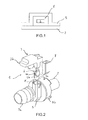
- the connector 3 is in this example clip on the sleeve 5, via clipping means 3c (see figures 3 and 6 ) formed on the support portion 3a of the connector 3 and cooperating with complementary means 5c (see figure 3 ) formed on the outer face of the housing 7 near its radially outer inlet 7a for the sleeve 5, by which is inserted the glue 8 and then the thermistor 4.
- the housing 7 ends with a bottom 7b (see figure 6 ) next to this input 7a and connected thereto by a wall 7c in this example generally prismatic and of almost rectangular section (see in particular the figure 4 ), whose radially inner face ends in contact with the tube 2.
- this wall 7c could alternatively present another type of geometry, for example generally cylindrical (ie of curved section, for example elliptical or circular), provided that its internal volume is sufficient to surround the thermistor 4.
- this wall 7c of the sleeve 5 is truncated by being completed by a concave circular arc portion 2a formed by the tube 2 itself which projects into the housing 7.
- the thermistor 4 once immersed in the housing 7 filled with the thermal glue 8 is surrounded by it being located at a distance from the tube 2 (approximately 1 mm separating the latter from the adjacent tab 4b of the thermistor 4).
- the glue 8 thus provides the thermal bridge between the "CTP" component 4a and the tube 2, also ensuring the seal around the thermistor 4 because it completely surrounds the latter and also the maintenance of the tube 2 in the connector because it is intended to strongly adhere to the constituent material of the tube 2 (eg aluminum).
- this thermal glue 8 an epoxy glue loaded with alumina and / or boron nitride, the epoxy glues being characterized in particular by a very good adhesion to aluminum and these charges to improve the thermal conductivity of the glue 8 without making it electrically conductive.
- the Applicant has established that a thermal conductivity value of 1 Wm -1 K -1 for this glue 8 gives very good results when the thermistor 4 is placed about 1 mm from the tube.
- the thermal glue 8 makes it possible to increase the heat exchange surface since it "brings back" heat diffused from the back of the thermistor 4 onto the tube 2.
- the Applicant has established by studying the steady-state heat flow in the housing 7 that the glue 8 effectively conducts heat to the tube 2, which serves as a diffuser for the fluid.
- the housing 7 for the thermistor 4 which is formed between the tube 2 and the wall 7c of the sleeve 5 and which is previously filled with the thermal glue 8 coming into contact with the tube 2, makes it possible to ensure that this thermistor 4 is well coated by the glue 8 after being immersed in it.
- This adhesive 8 must be provided sufficiently liquid to prevent the imprisonment of air bubbles, because the air is a very poor conductor of heat.
- this housing 7 makes it possible to overcome the differences in the volume of glue 8 required from one tube 2 to another because of the usual imperfections of these tubes 2, thus ensuring a sufficient volume of glue 8 (this volume is represented symbolically at the figure 2 , where it is seen that it marries the walls 2a, 7a and 7c of the housing 7) to properly wrap the thermistor 4 and tabs 4b, 4c associated which must all be protected from ambient humidity.
Landscapes
- Engineering & Computer Science (AREA)
- General Engineering & Computer Science (AREA)
- Mechanical Engineering (AREA)
- Measuring Temperature Or Quantity Of Heat (AREA)
Applications Claiming Priority (1)
| Application Number | Priority Date | Filing Date | Title |
|---|---|---|---|
| FR0901532A FR2943718B1 (fr) | 2009-03-30 | 2009-03-30 | Dispositif de rechauffage d'un fluide,son procede d'assemblage et systeme de raccordement l'incorporant pour embout d'admission d'air d'un tuyau de fuite des gaz. |
Publications (1)
| Publication Number | Publication Date |
|---|---|
| EP2236780A1 true EP2236780A1 (de) | 2010-10-06 |
Family
ID=41066745
Family Applications (1)
| Application Number | Title | Priority Date | Filing Date |
|---|---|---|---|
| EP10158170A Withdrawn EP2236780A1 (de) | 2009-03-30 | 2010-03-29 | Vorrichtung zum Vorwärmen eines Fluids, ihr Montageverfahren und ein Verbindungssystem zwischen der Luftleitung und der Kurbelgehäuse-Entlüftungsleitung, das sie umfasst, für einen Verbrennungsmotor |
Country Status (2)
| Country | Link |
|---|---|
| EP (1) | EP2236780A1 (de) |
| FR (1) | FR2943718B1 (de) |
Cited By (4)
| Publication number | Priority date | Publication date | Assignee | Title |
|---|---|---|---|---|
| DE102010033757A1 (de) * | 2010-08-09 | 2012-02-09 | Dbk David + Baader Gmbh | Fluidleiteinrichtung |
| WO2014184333A1 (de) * | 2013-05-17 | 2014-11-20 | Dbk David + Baader Gmbh | Blowby-einrichtung |
| KR20190002326U (ko) * | 2018-03-09 | 2019-09-18 | 허친슨 | 열 내연 엔진을 위한 유체를 가열하기 위한 장치 |
| CN110500465A (zh) * | 2018-05-17 | 2019-11-26 | 哈金森公司 | 用于机动车辆的流体连接装置 |
Families Citing this family (2)
| Publication number | Priority date | Publication date | Assignee | Title |
|---|---|---|---|---|
| FR3106390B1 (fr) | 2020-01-20 | 2021-12-10 | Hutchinson | Coque chauffante pour raccord trois voies |
| FR3106365B1 (fr) | 2020-01-20 | 2022-10-14 | Hutchinson | Dispositif de raccordement fluidique et de chauffage de fluide |
Citations (5)
| Publication number | Priority date | Publication date | Assignee | Title |
|---|---|---|---|---|
| WO1999033497A1 (en) * | 1997-12-31 | 1999-07-08 | A.T.C.T.- Advanced Thermal Chips Technologies Ltd. | Autoclave device and ptc heating arrangement for use therewith |
| EP1164264A1 (de) * | 2000-06-14 | 2001-12-19 | DBK David + Baader GmbH | Blowby-Heizung |
| US6546921B1 (en) * | 2002-04-30 | 2003-04-15 | Miniature Precision Components | Heated PCV valve |
| WO2004003420A1 (de) * | 2002-06-27 | 2004-01-08 | David & Baader-Dbk-Spezial-Fabrik Elektrischer Apparate Und Heizwiderstaende Gmbh | Heizvorrichtung für eine fluidleitung und verfahren zur herstellung |
| US20070186913A1 (en) * | 2006-02-14 | 2007-08-16 | Honda Motor Co., Ltd. | Engine with breather apparatus |
-
2009
- 2009-03-30 FR FR0901532A patent/FR2943718B1/fr not_active Expired - Fee Related
-
2010
- 2010-03-29 EP EP10158170A patent/EP2236780A1/de not_active Withdrawn
Patent Citations (6)
| Publication number | Priority date | Publication date | Assignee | Title |
|---|---|---|---|---|
| WO1999033497A1 (en) * | 1997-12-31 | 1999-07-08 | A.T.C.T.- Advanced Thermal Chips Technologies Ltd. | Autoclave device and ptc heating arrangement for use therewith |
| EP1164264A1 (de) * | 2000-06-14 | 2001-12-19 | DBK David + Baader GmbH | Blowby-Heizung |
| EP1164264B1 (de) | 2000-06-14 | 2005-11-02 | DBK David + Baader GmbH | Blowby-Heizung |
| US6546921B1 (en) * | 2002-04-30 | 2003-04-15 | Miniature Precision Components | Heated PCV valve |
| WO2004003420A1 (de) * | 2002-06-27 | 2004-01-08 | David & Baader-Dbk-Spezial-Fabrik Elektrischer Apparate Und Heizwiderstaende Gmbh | Heizvorrichtung für eine fluidleitung und verfahren zur herstellung |
| US20070186913A1 (en) * | 2006-02-14 | 2007-08-16 | Honda Motor Co., Ltd. | Engine with breather apparatus |
Cited By (6)
| Publication number | Priority date | Publication date | Assignee | Title |
|---|---|---|---|---|
| DE102010033757A1 (de) * | 2010-08-09 | 2012-02-09 | Dbk David + Baader Gmbh | Fluidleiteinrichtung |
| WO2014184333A1 (de) * | 2013-05-17 | 2014-11-20 | Dbk David + Baader Gmbh | Blowby-einrichtung |
| US9777608B2 (en) | 2013-05-17 | 2017-10-03 | Dbk David + Baader Gmbh | Blow-by device |
| KR20190002326U (ko) * | 2018-03-09 | 2019-09-18 | 허친슨 | 열 내연 엔진을 위한 유체를 가열하기 위한 장치 |
| CN110500465A (zh) * | 2018-05-17 | 2019-11-26 | 哈金森公司 | 用于机动车辆的流体连接装置 |
| CN110500465B (zh) * | 2018-05-17 | 2022-08-02 | 哈金森公司 | 用于机动车辆的流体连接装置 |
Also Published As
| Publication number | Publication date |
|---|---|
| FR2943718B1 (fr) | 2015-06-26 |
| FR2943718A1 (fr) | 2010-10-01 |
Similar Documents
| Publication | Publication Date | Title |
|---|---|---|
| EP2236780A1 (de) | Vorrichtung zum Vorwärmen eines Fluids, ihr Montageverfahren und ein Verbindungssystem zwischen der Luftleitung und der Kurbelgehäuse-Entlüftungsleitung, das sie umfasst, für einen Verbrennungsmotor | |
| EP3277542B1 (de) | Durchgangsanordnung für einen kabelbaum in einem triebwerk | |
| FR2899683A1 (fr) | Capteur de temperature et procede de fabrication de celui-ci | |
| EP2828630A1 (de) | Temperatursensor | |
| FR2979017A1 (fr) | Capteur d'echappement pour un moteur a combustion interne | |
| FR2711393A1 (fr) | Système comprenant une prise de température notamment sur tubulure plastique. | |
| WO2013149971A1 (fr) | Dispositif de chauffage électrique de fluide pour véhicule automobile et procédé d'assemblage dudit dispositif de chauffage | |
| WO2020193597A1 (fr) | Boitier de protection pour capteur de température de véhicule | |
| EP3555457B1 (de) | Leitung zur durchführung von flüssigem kühlmittel für einen verbrennungsmotor eines kraftfahrzeugs | |
| EP3569910B1 (de) | Flüssigkeitsanschlussvorrichtung für ein kraftfahrzeug | |
| FR2973604A1 (fr) | Dispositif de fixation d'un conducteur electrique dans un compresseur | |
| EP3538803B1 (de) | Verbindungskörper, verschraubungen und hydraulisches system für den durchgang einer flüssigkeit zwischen zwei hydraulischen kreisläufen, zugehöriges verfahren und montage | |
| FR3000133A1 (fr) | Ligne d'echappement de vehicule automobile comportant une rotule perfectionnee | |
| FR2853710A1 (fr) | Ensemble thermostatique a commande electrique et vanne thermostatique equipee d'un tel ensemble | |
| EP3286535A1 (de) | Hochtemperatursensor mit integriertem verbinder | |
| FR2851315A1 (fr) | Vanne de regulation d'un fluide equipee d'un dispositif de chauffage | |
| EP4479638B1 (de) | Verfahren zur herstellung eines kreislaufes für ein kraftfahrzeug | |
| FR2984494A1 (fr) | Capteur de temperature | |
| FR2906576A1 (fr) | Agencement de refroidissement d'un injecteur comportant un empilement de rondelles. | |
| FR2906575A1 (fr) | Agencement de refroidissement d'un injecteur comportant deux bagues coaxiales. | |
| FR3062477A1 (fr) | Capteur de temperature avec joint d'etancheite elastomere | |
| FR3146767A1 (fr) | Boitier de protection de connecteurs electriques dans un environnement chaud | |
| FR3078742A1 (fr) | Detection electrique du raccordement d’un dispositif de rechauffage de fluide pour un moteur thermique a combustion interne | |
| EP1611934B1 (de) | Fluidfilter mit Sensor | |
| WO2026078091A1 (fr) | Radiateur électrique pour véhicule automobile |
Legal Events
| Date | Code | Title | Description |
|---|---|---|---|
| PUAI | Public reference made under article 153(3) epc to a published international application that has entered the european phase |
Free format text: ORIGINAL CODE: 0009012 |
|
| AK | Designated contracting states |
Kind code of ref document: A1 Designated state(s): AT BE BG CH CY CZ DE DK EE ES FI FR GB GR HR HU IE IS IT LI LT LU LV MC MK MT NL NO PL PT RO SE SI SK SM TR |
|
| AX | Request for extension of the european patent |
Extension state: AL BA ME RS |
|
| 17P | Request for examination filed |
Effective date: 20110321 |
|
| STAA | Information on the status of an ep patent application or granted ep patent |
Free format text: STATUS: THE APPLICATION IS DEEMED TO BE WITHDRAWN |
|
| 18D | Application deemed to be withdrawn |
Effective date: 20161001 |