EP2236966A2 - Unité de commande pour un dispositif de séchage, dispositif de séchage et ensemble de séchage - Google Patents
Unité de commande pour un dispositif de séchage, dispositif de séchage et ensemble de séchage Download PDFInfo
- Publication number
- EP2236966A2 EP2236966A2 EP10157768A EP10157768A EP2236966A2 EP 2236966 A2 EP2236966 A2 EP 2236966A2 EP 10157768 A EP10157768 A EP 10157768A EP 10157768 A EP10157768 A EP 10157768A EP 2236966 A2 EP2236966 A2 EP 2236966A2
- Authority
- EP
- European Patent Office
- Prior art keywords
- control unit
- drying
- drying device
- set forth
- module
- Prior art date
- Legal status (The legal status is an assumption and is not a legal conclusion. Google has not performed a legal analysis and makes no representation as to the accuracy of the status listed.)
- Withdrawn
Links
Images


Classifications
-
- F—MECHANICAL ENGINEERING; LIGHTING; HEATING; WEAPONS; BLASTING
- F26—DRYING
- F26B—DRYING SOLID MATERIALS OR OBJECTS BY REMOVING LIQUID THEREFROM
- F26B3/00—Drying solid materials or objects by processes involving the application of heat
- F26B3/02—Drying solid materials or objects by processes involving the application of heat by convection, i.e. heat being conveyed from a heat source to the materials or objects to be dried by a gas or vapour, e.g. air
-
- F—MECHANICAL ENGINEERING; LIGHTING; HEATING; WEAPONS; BLASTING
- F26—DRYING
- F26B—DRYING SOLID MATERIALS OR OBJECTS BY REMOVING LIQUID THEREFROM
- F26B21/00—Arrangements for supplying or controlling air or other gases for drying solid materials or objects
- F26B21/30—Controlling, e.g. regulating, parameters of gas supply
-
- E—FIXED CONSTRUCTIONS
- E04—BUILDING
- E04B—GENERAL BUILDING CONSTRUCTIONS; WALLS, e.g. PARTITIONS; ROOFS; FLOORS; CEILINGS; INSULATION OR OTHER PROTECTION OF BUILDINGS
- E04B1/00—Constructions in general; Structures which are not restricted either to walls, e.g. partitions, or floors or ceilings or roofs
- E04B1/62—Insulation or other protection; Elements or use of specified material therefor
- E04B1/70—Drying or keeping dry, e.g. by air vents
Definitions
- the invention relates to a control unit for a drying device as set forth in the preamble of claim 1.
- the invention relates also to a drying device as set forth in claim 13.
- the invention relates to a drying arrangement as set forth in claim 15.
- An object of the invention is to enhance and simplify the operation and connection of dryers in worksite conditions used in the drying of premises, parts of buildings.
- Prior known e.g. from Finnish patent application Fl 20050121 , is an air circulating flat surface dryer, comprising a targeting box sealed against a surface to be dried, a fan inside the box, electrical resistances and a duct system. An electrical connection for the fan and the electrical resistances is integrated as a permanent part of the circulating air flat surface dryer.
- An object of the invention is to eliminate the drawbacks associated with dryers of the above type, i.e. drying devices and drying arrangements.
- Another object of the invention is to provide a new drying arrangement, which is particularly apt for the drying of premises, such as floors of premises, or generally for the drying of flat surfaces in parts of a building.
- a control unit of the invention for a drying device is characterized by what is presented in claim 1. Preferred embodiments for the invention are presented in the dependent claims.
- the control unit according to the invention is designed for a drying device of the type intended especially for the drying of fixed structures, said drying device including most preferably a fan and an electrical resistance, and said control unit enabling the drying device to be controlled and connected to and disconnected from an electric power supply, most preferably a mains electricity network.
- control unit is arranged as a module, comprising:
- the drying device according to the invention is intended for the drying of damp or moisture-affected parts of a building or the like, and it comprises at least a fan and an electrical resistance and is connectable to an electric power supply, most preferably to a mains electricity network.
- the drying device is provided with a connector, especially a second connector component, by way of which it is connectable to a control unit as set forth in any of the claims directed to a control unit, such as to a control unit as defined above.
- the drying arrangement according to the invention is intended for the drying of damp or moisture-affected parts of a building or the like, said drying arrangement comprising a plurality of drying devices, such as flat surface dryers, including most preferably a fan and an electrical resistance, and a control unit as set forth in any of the claims directed to a control unit, such as a control unit as defined above, for controlling the drying devices and connecting and disconnecting the same to and from an electric power supply, most preferably an electricity network.
- a control unit such as a control unit as defined above
- a benefit offered by the invention is that a single module of the invention enables two or most preferably a plurality of drying devices to be connected thereto, said devices being controlled within the extent of one and the same heating cycle or optionally by alternating the heating cycles. Alternating the heating cycles of drying devices offers the benefit of having a mains electricity network or the like subjected to a load more consistent than in the case of just a single heating cycle.
- Another benefit offered by the invention is that the module enables an external device to be connected thereto for complementing a module control and monitoring.
- Still another benefit of the invention is that possible fault alarms or the like of the drying devices are capable of being centralized in the module and in such a way that the supply of electricity at least to the electrical resistance of a drying device is discontinued by means of a second coupling element of the module.
- the drying arrangement provided by the invention is intended particularly for the drying of premises or parts of buildings. In the case of water damage incidents or the like, it is especially the floors which soak plenty of moisture that must be removed from the structures by an appropriate drying operation.
- Various flat surface dryers such as the one disclosed in the above-cited Finnish patent application Fl-20050121 , have been developed for the purpose.
- the drying arrangement according to the invention comprises a plurality of drying devices 1, such as flat surface dryers 10.
- the drying devices 1; 10 are adapted to cover at least part of a water-logged, wetted floor area or the like LA (cf. fig. 2 ).
- the drying device 1; 10 of the invention comprises a fan 110 for the circulation of air and at least one electrical resistance 120 for the heating of air (cf. fig. 4 ).
- the fan 110 and the electrical resistance 120 are accommodated in a targeting box 130 provided with a suitable duct system 140.
- a control unit 2 In communication with the drying device 1; 10 is a control unit 2 for controlling the drying device and for connecting and disconnecting the same to and from an electric power supply, most preferably an electricity network 3.
- the control unit 2 is designed as an independent module 20.
- the control unit 2 and the module 20 comprise a plurality of connectors 5; 5 1 , 5 2 , 5 3 ,...,5 6 , a timer element 21 and a first coupling element 22, as well as an electrical connection 4.
- the module 20 is provided with a plurality of connectors 5; 5 1 , 5 2 , 5 3 ,...,5 6 , especially first connector components 51, most preferably female connector components, by way of which the control unit 2, especially the elements 21, 22, is connectable to not less than two, most preferably to a plurality of drying devices 1; 1 1 , 1 2 , 1 3 ,.., 1 5 , as illustrated specifically in fig. 3 .
- Each drying device 1 is respectively provided with a connecting wire 150 and with connectors, i.e. second connector components 52, most preferably male connector components, compatible with the module's 20 connectors 5, i.e. the first connector components 51, for attaching the drying device 1 in a detachable manner to the respective module, as revealed e.g. in fig. 4 .
- the first coupling element 22 comprises preferably a controlled on/off switch, such as a relay, which comprises a control member 221 and a coupler 222 by which the drying devices 1; 1 1 , 1 2 , 1 3 ,.., 1 5 , coupled with the connectors 5; 5 1 , 5 2 , 5 3 ,...,5 6 , are connected to an electric power supply (cf. fig. 3 ).
- the first coupling element 22 and the timer element 23 are interconnected with each other, such that the coupling element 22, especially the coupler 222, is controlled by the timer element 23. This enables timing the operation of the drying device 1; 1 1 , 1 2 , 1 3 ,.., 1 5 and connecting and disconnecting the same to and from an electric power supply in response to a clock in the timer element.
- the module 20 is provided with an electrical connection 4 for connecting an electricity network 3 or the like electric power supply to the control unit 2, and further from the control unit 2, by way of the connectors 5; 51, to one or more drying devices 1; 1 1 , 1 2 , 1 3 ,.., 1 5 .
- the electrical connection 4 comprises most preferably a conventional electric wire 41 and an insertion plug 42 for coupling the control unit 2 to a socket-outlet 31 linked to the electricity network 3.
- the first coupling element 22 of the control unit 2 comprises, not a controlled on/off switch, but instead a controlled changeover switch 222a (cf. fig. 3 ).
- At least two drying devices, or optionally drying device groups 1A and 1B as in the exemplary embodiment of figs. 1 and 2 are connectable and respectively disconnectable by way of respective connector groups 5A, 5B in an alternating manner to and from the electrical connection 4 and thereby to and from the electricity network 3.
- the changeover switch 222a is bi-positional, i.e. it is provided with two changeover terminals 2221 and 2222, enabling a changeover of connection therebetween.
- the changeover switch 222a further has its changeover terminals connected by way of conductors to two connector groups, i.e. to the first and second connector groups 5A, 5B, and to the respective drying device groups 1A, 1B connected thereby to the connectors 5; 5 1 , 5 2 , 5 3 and 5, 5 4 , 5 5 of the connector groups.
- the changeover switch 222a is multi-positional, i.e. the changeover switch includes several, e.g. 3 pcs of changeover terminals, between which the connection can be varied, and respectively several, such as 3 pcs of connector groups and respectively drying device groups, which are thus in an alternating manner capable of being coupled to and uncoupled from the electrical connection 4 and thereby to and from the electricity network 3, respectively.
- the module 20 further comprises a second coupling element 23 for coupling and uncoupling the drying devices 1; 1 1 ; 1 2 , 1 3 ,.., 1 5 , coupled with the connectors 5; 5 1 , 5 2 , 5 3 ,...,5 6 , to and from an electric power supply in response to a separate control message, e.g. upon receiving a fault alarm or a separate control message from a drying device or an accessory 70.
- a separate control message e.g. upon receiving a fault alarm or a separate control message from a drying device or an accessory 70.
- the second coupling element 23 comprises also a controlled on/off switch, such as a relay, which respectively comprises a control member 231 and a coupler 232.
- a controlled on/off switch such as a relay
- the module 20 is accommodated in an enclosure 6; preferably a closed enclosure.
- the module 20 has its connectors 5; 5 1 , 5 2 , 5 3 ,...,5 6 , especially its first or female connectors 51, mounted on the enclosure walls, particularly on side walls 61, 62.
- the electrical connection 4 has its electric wire 41 delivered through a wall of the enclosure 6 and attached appropriately to elements of the module, such as to the first and second coupling elements 21, 22.
- An advantage offered by the enclosure 6 is the possibility of placing the module 20 outside the drying device/drying devices and at a suitable distance therefrom. In addition, the enclosure 6 protects the module 20.
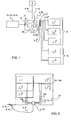
- the connectors 5; 5 1 , 5 2 , 5 3 ,...,5 6 of the module 20, especially its first or female connectors 51, and the respective second or male connectors 52 of the drying devices 1, are multi-terminal connectors.
- the connectors 5; 51, 52 have a number of terminals 5a, such as e.g. six terminals 5a 1 , 5a 2 , 5a 3 ,..., 5a 6 , and preferably also a protective earth terminal 5a PE , by way of which the module 20 and the drying devices are attachable to each other in a predetermined manner.
- the connector 5; 51, 52 is preferably cylindrical in terms of its body and circular in its cross-section. In this case, the connector has its terminals located on the body along the circumference in a peripheral area of the connector, as specifically shown in fig. 5 .
- control unit 2 and the module 20 further comprise a measuring instrument 7, such as an electrical energy measuring element 71, for measuring the electrical energy spent by one or more drying devices 1 and hence for tracking the power consumption.
- a measuring instrument 7 such as an electrical energy measuring element 71, for measuring the electrical energy spent by one or more drying devices 1 and hence for tracking the power consumption.
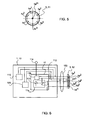
- phase conductor (electrical conductor) 410 and an O-conductor 411 of the electrical connection, respectively.
- These terminals are principally intended for electrically operated elements and equipment of the drying device 1;10 with the exception of one more electrical resistances 120 intended for heating.
- the electrical connection has its phase conductor 410 connected by way of the electrical energy measuring element 71, such as a kWh meter 711, to the first terminal 5a 1 .
- the electrical connection has its O-conductor 411 connected directly to the second terminal 5a 2 .
- the electrical connection has its O-conductor 411 connected also to a third terminal 5a 3 by way of the series-connected second coupling element's 23 switch 232 and the first coupling element's 22 switches 222.
- the first coupling element 22 is provided with a changeover switch 222a, whereby its first changeover terminal 2221 is connected to a third terminal 5a 3 of the first connector group's 5A connectors 5; 51 and, respectively, its second changeover terminal 2222 is connected to a third terminal 5a 3 of the second connector group's 5B connectors 5; 51.
- the third terminal 5a 3 is intended for the electrical resistance 120 of a drying device 1; 10.
- the connector 5 has a third terminal 5a 3 of its second connector component 52 attached by way of an appropriate conductor in the connection wire 150 to a relevant electrical resistance 120.
- this terminal 5a 3 the electrical resistance of a drying device 1; 10 is controlled to switch on and off, i.e. is coupled to and uncoupled from an electric power supply.
- a fourth terminal 5a 4 of the connector 5; 51, 52 is a fault message terminal, which is reserved for fault alarms, malfunction notifications or the like information coming from the drying device 1; 10. This will be discussed subsequently further in connection with figs. 6 and 8 . Furthermore, a fifth terminal 5a 5 of the connector 5; 51, 52 is vacant, while a sixth terminal 5a 6 is reserved for disrupting the heating of a drying device 1; 10, i.e. for switching off the power supply to the electrical resistances 120, said switching-off being particularly implementable by means of a control external of the module 20, which control is obtainable from an accessory 70 attachable to the module 20 by way of the connectors 5; 51, 52, as will be subsequently described by way of example in reference to figs. 6 and 8 .
- the connector has its fifth terminal 5a 5 reserved for some appropriate extra application.
- the module 20 has the fourth terminal 5a 4 of its connector 5; 51 attached by way of an indicator lamp 9, such as an LED lamp, to the phase conductor 410.
- This terminal is adapted to function as a detector for fault alarms or the like of the drying device 1; 10.
- the indicator lamp 9 is adapted to switch on as a fault alarm is received from one or more drying devices.
- the electric wire 41 has its protective earth conductor 412 connected to the seventh terminal 5a PE and at the same time, among other things, to the enclosure 6 of the module 20.
- the drying device 1; 10 of the invention is provided with a fan 110 and an electrical resistance 120.
- the electrical components of a drying device are connected to a wire 150, and to a connector 5 included therein, particularly to a second connector component 52, most preferably to a male connector component (cf. e.g. fig. 4 ).
- the fan 110 and the electrical resistance 120 are connected by way of appropriate conductors to the connector's 5; 52 first and second terminals 5a 1 , 5a 2 with which the phase conductor 410 and respectively the O-conductor 411 are set to be attached as the second connector component 52 is attached to the first connector component 51 and at the same time to the module 20 and to the control unit 2.
- the drying device 1;10 comprises an alarm element 11, as specifically shown in fig. 6 .
- the alarm element 11 includes at least one sensor 11a, an alarm controller 11b, having the sensor coupled therewith, and a coupling element 11c.
- the sensor 11a is adapted to detect anomalies in the operation of a drying device and/or in the drying process.
- the sensor 11a is e.g. a temperature sensor for measuring temperature and for detecting thereby e.g. the exceeding of an allowed maximum temperature, a pressure sensor for detecting pressure generated by the fan and for monitoring thereby the operation of the fan 110.
- the alarm controller 11b is adapted to receive messages of the sensor 11a and to analyze possible malfunctions or the like.
- the coupling element 11c is most preferably established by a controlled on/off switch, such as a relay, which comprises a control member 111 and a coupler 112.
- the alarm controller 11b is connected to the coupling element 11c and it sets the coupling element in active mode upon detecting a malfunction or the like in the drying device and/or in the drying process.
- the sensor 11a is used for monitoring the condition of a drying device and/or its immediate vicinity, such as the temperature of a spot being dried.
- a message such as e.g. a temperature value, is supplied from the sensor to the alarm controller 11b.
- the alarm controller 11b is used for analyzing the sensor message, such as a measured temperature value, e.g. by comparing it with preset limit values for a measurement message, such as temperature.
- a fault alarm message will be emitted to the coupling element 11c, particularly to its control member 111.
- the coupler 112 of the coupling element 11c is closed in response to a command from the control member 111 and, by means of the coupler 112, the fourth terminal 5a 4 of the connector 5; 51, 52 is connected to the second terminal 5a 2 and further thereby to the electrical connection's 0-terminal, i.e. to earth.
- the indicator lamp 9 in the control unit 2 and in the module 20 switches on ands indicates that a fault has occurred.
- control unit 2 and particularly the module can be fitted, through the intermediary of a connector 5; 51, 52, with accessories 70, especially tracking and control elements, for monitoring and/or controlling the drying devices 1 attached to the module 20.
- accessories include e.g. a temperature measuring element 72, a moisture measuring element 73, and a communications element 8.
- One accessory 70 attachable to the control unit 2 and especially to the module 20 by way of the connector 5, is a temperature measuring element 72 for tracking the temperature of a presently dried project (cf. fig. 7 ).
- the temperature measuring element 72 is a separate element, which is detachably attachable by means of a connector 5, particularly by means of a second male connector component 52, and by means of a wire 150a connected thereto, to one of the module's 20 connectors, particularly to a first female connector component 51.
- the temperature measuring element 72 comprises a temperature sensor 721 for tracking the temperature of a presently dried project, and preferably also a coupling element 701 which includes a control member 702 and an on/off switch 703.
- the coupling element 701 is controlled by means of an appropriate limit temperature value, such as a maximum value.
- the switch 703 is disposed between the first and sixth terminals 5a 1 , 5a 6 of a connector 5; 52. Between the respective terminals in a connector 5; 51 of the module is the first coupling element 21.
- the coupling element's 701 control member 702 is adapted to operate the switch 703, such that it closes an electric circuit present between the first and sixth terminals 5a 1 , 5a 6 , as a result of which the control member 231 of the module's 20 second coupling element 23 receives such a command that the switch 232 disrupts the supply of power to the electrical resistance 120 of a drying device 1; 10 and the heating is discontinued. It should be noted that bringing out a temperature measurement value is also possible by way of the terminal 5a 5 of a connector 5; 51, 52, which terminal has been left vacant in the application of fig. 3 .
- the moisture measuring element 73 for tracking the moisture condition, such as relative humidity, of a presently dried project (cf. also fig. 7 ).
- the moisture measuring element 73 comprises a moisture sensor 731 for tracking the moisture of a presently dried project, and preferably also a coupling element 701 which includes a control member 702 and an on/off switch 703.
- the coupling element 701 is controlled by means of an appropriate limit moisture value, such as a minimum value.
- the construction and operation are analogous to those of the above-described temperature measuring element 72.
- the switch 703 When the moisture condition of a presently dried project is discovered to fall short of a set limit moisture value, the switch 703 is operated to close an electric circuit present between the first and sixth terminals 5a 1 , 5a 6 , as a result of which the control member 231 of the module's 20 second coupling element 23 receives such a command that the switch 232 disrupts the supply of power to the electrical resistance 120 of a drying device 1; 10 and the heating is discontinued. It should be noted in this case as well that bringing out a moisture measurement value is also possible by way of the terminal 5a 5 of a connector 5; 51, 52, which terminal has been left vacant in the application of fig. 3 .
- the accessory 70 is integrable with the control unit 2 and the module 20.
- the actual measuring sensors such as a temperature sensor 721 and a moisture sensor 731, be attachable, along with possible electronic sensor circuits thereof, by way of the connector 5; 51, 52 to the module 20 and to respective measuring elements integrated therewith.
- the control unit 2, and especially the module 20 can be fitted, by way of a connector 5; 51, 52, with a communications element 8 for communicating information between the drying device 1; 1 1 , 1 2 , 1 3 ,.., 1 5 and the user ( fig. 8 ).
- the communications element 8 comprises a wireless transceiver unit 81, which preferably operates in a radio frequency range.
- the wireless transceiver unit 81 comprises most preferably a mobile communicator, such as a GSM mobile communicator.
- the transceiver unit 81 is coupled between the first and second terminals 5a 1 , 5a 2 of a connector 5, particularly a male connector component 52, by way of which terminals it receives electric power from the module 20 and further from the electric power supply 3 by way of the electrical connection 4.
- the communications element has its first coupling unit 82, which is established by a relay or the like, disposed between the first and fourth terminals 5a 1 , 5a 4 .
- the coupling unit 82 has its control member 821, such as a relay winding, engaged with the discussed terminals, and its switch 822 fitted in the input of the transceiver unit 81.
- the communications element 8 works most preferably as follows.
- the first coupling element's 82 control member 821 such as a relay winding, operates and closes the switch 822, whereby the transceiver unit's 81 input is supplied with an appropriate message, such as a change of voltage level, which is detected.
- This change is interpreted as an alarm message and transmitted in an appropriate mode, such as in a voice, text or data message, forward to a predetermined destination, such as to a specific subscriber number in the case of a mobile communicator.
- the communications element 8 further comprises a second coupling element 83, established by a relay or the like, having its switch 832 disposed between the first and sixth terminals 5a 1 , 5a 6 .
- the second coupling element 83 has its control member 831, such as a relay winding, coupled with an appropriate output of the transceiver unit 81.
- the second coupling element 83 When an appropriate message, such as a text message, is received by the transceiver unit 81, the second coupling element 83 has its control member 831 adapted to supply the switch 832 with a control command for closing an electric circuit present between the first and sixth terminals 5a 1 ; 5a 6 , whereby the control member 231 of the module's 20 second coupling element 23 receives such a control command that the switch 232 disrupts the supply of power to the electrical resistance 120 of a drying device 1; 10 and the heating is discontinued.
- the heating can be activated with an appropriate second message, such as a second text message, which is received by the transceiver unit 81.
- the second coupling element's 83 control member 831 is adapted to supply the switch 832 with a control command for opening an electric circuit present between the first and sixth terminals 5a 1 , 5a 6 , whereby the control member 231 of the module's 20 second coupling element 23 receives such a control command that the switch 232 closes and allows again the supply of power to the electrical resistance 120 of a drying device 1; 10.
- the communications element 8 is integrable with the control unit 2 and with the module 20. This enables applying the same procedure which is used for integrating an electrical energy measuring element 71, fig. 3 , with the actual module 20.
- the invention relates also to a drying arrangement, which is particularly intended for the drying of premises, such as moist or wetted parts of a building or the like.
- the drying arrangement such as an arrangement as shown in figs. 1 and 3 , comprises a plurality of drying devices 1; 1 1 , 1 2 , 1 3 ,.., 1 5 , such as flat surface dryers 10.
- Each drying device 1; 10 is most preferably provided with a fan 11 and at least one electrical resistance 12.
- the drying arrangement comprises a control unit 2 as set forth in any of the preceding embodiments, which has been configured as a module 20, for controlling the drying devices 1 and for connecting and disconnecting the same to and from an electric power supply, most preferably the electricity network 3, as well as for tracking the operation of the drying device.
Landscapes
- Engineering & Computer Science (AREA)
- Mechanical Engineering (AREA)
- General Engineering & Computer Science (AREA)
- Architecture (AREA)
- Physics & Mathematics (AREA)
- Electromagnetism (AREA)
- Civil Engineering (AREA)
- Structural Engineering (AREA)
- Life Sciences & Earth Sciences (AREA)
- Microbiology (AREA)
- Drying Of Solid Materials (AREA)
Applications Claiming Priority (1)
| Application Number | Priority Date | Filing Date | Title |
|---|---|---|---|
| FI20095344A FI20095344A (fi) | 2009-03-31 | 2009-03-31 | Ohjausyksikkö kuivauslaitetta varten, kuivauslaite ja kuivausjärjestely |
Publications (2)
| Publication Number | Publication Date |
|---|---|
| EP2236966A2 true EP2236966A2 (fr) | 2010-10-06 |
| EP2236966A3 EP2236966A3 (fr) | 2015-09-09 |
Family
ID=40510341
Family Applications (1)
| Application Number | Title | Priority Date | Filing Date |
|---|---|---|---|
| EP10157768.2A Withdrawn EP2236966A3 (fr) | 2009-03-31 | 2010-03-25 | Unité de commande pour un dispositif de séchage, dispositif de séchage et ensemble de séchage |
Country Status (2)
| Country | Link |
|---|---|
| EP (1) | EP2236966A3 (fr) |
| FI (1) | FI20095344A (fr) |
Cited By (1)
| Publication number | Priority date | Publication date | Assignee | Title |
|---|---|---|---|---|
| DE102017108537A1 (de) * | 2017-04-21 | 2018-10-25 | Stefan Bendrich | Steuer- und Regeleinheit für mobile Gebäudetrocknungsgeräte |
Family Cites Families (3)
| Publication number | Priority date | Publication date | Assignee | Title |
|---|---|---|---|---|
| FR2762470B3 (fr) * | 1997-04-21 | 1999-07-23 | Francis Scarella | Ensemble programmateur, delesteur et enregistreur pour la gestion de convecteurs electriques |
| FR2879853A1 (fr) * | 2004-12-21 | 2006-06-23 | Epiq | Appareil et procede d'attribution de puissance electrique |
| FI119952B (fi) * | 2005-02-03 | 2009-05-15 | Korpikorpi Oy | Kiertoilmatasokuivaaja |
-
2009
- 2009-03-31 FI FI20095344A patent/FI20095344A/fi not_active Application Discontinuation
-
2010
- 2010-03-25 EP EP10157768.2A patent/EP2236966A3/fr not_active Withdrawn
Cited By (1)
| Publication number | Priority date | Publication date | Assignee | Title |
|---|---|---|---|---|
| DE102017108537A1 (de) * | 2017-04-21 | 2018-10-25 | Stefan Bendrich | Steuer- und Regeleinheit für mobile Gebäudetrocknungsgeräte |
Also Published As
| Publication number | Publication date |
|---|---|
| FI20095344A7 (fi) | 2010-10-01 |
| FI20095344A (fi) | 2010-10-01 |
| FI20095344A0 (fi) | 2009-03-31 |
| EP2236966A3 (fr) | 2015-09-09 |
Similar Documents
| Publication | Publication Date | Title |
|---|---|---|
| EP2871730B1 (fr) | Système de tableau de distribution | |
| EP2342666B1 (fr) | Appareil et procédé de mappage d'un réseau câblé | |
| CN113597658A (zh) | 集成的电力面板 | |
| CN102265469A (zh) | 电插座系统内部的无线收发器 | |
| US20090167494A1 (en) | Intelligent Power Cord Device ( iCord) | |
| JP2018508916A (ja) | 電力スイッチをまたぐIoT通信 | |
| EP3271987B1 (fr) | Dispositifs de câblage intelligent | |
| CN106299904A (zh) | 线缆结构、电源线结构和电器设备 | |
| EP3419040A1 (fr) | Module complémentaire pour un dispositif électrique monté sur rail din | |
| CN101640345A (zh) | 数字式自动监控及断电的安全电源插座 | |
| EP2236966A2 (fr) | Unité de commande pour un dispositif de séchage, dispositif de séchage et ensemble de séchage | |
| US20130106199A1 (en) | Master slave radio control system | |
| CN108646090B (zh) | 电表和电表控制系统 | |
| EP3104180A1 (fr) | Dispositif de surveillance des paramètres électriques d'une charge électrique | |
| EP2221586A1 (fr) | Connexion d'alimentation électrique | |
| WO2015114338A1 (fr) | Fiche d'alimentation électrique, douille, insert et systèmes | |
| JP4866283B2 (ja) | 動作保証機能付集合住宅幹線電流制御システム | |
| KR20080112781A (ko) | 타임설정이 가능한 그린 콘센트 | |
| US20190157817A1 (en) | Smart receptacle having plug blade detection | |
| CN212908381U (zh) | 模块化漏电保护器及模块化智能漏电保护插座 | |
| KR20150113058A (ko) | 통신 모듈 어댑터 | |
| KR102132920B1 (ko) | 전력 절감 장치를 포함하는 전력 모니터링 시스템 | |
| JP5786192B2 (ja) | 電力管理機能付きコンセント | |
| CN110915083A (zh) | 电气设备和相关联的附加功能模块 | |
| EP1306955A3 (fr) | Réseau à haute tension mobile |
Legal Events
| Date | Code | Title | Description |
|---|---|---|---|
| PUAI | Public reference made under article 153(3) epc to a published international application that has entered the european phase |
Free format text: ORIGINAL CODE: 0009012 |
|
| AK | Designated contracting states |
Kind code of ref document: A2 Designated state(s): AT BE BG CH CY CZ DE DK EE ES FI FR GB GR HR HU IE IS IT LI LT LU LV MC MK MT NL NO PL PT RO SE SI SK SM TR |
|
| AX | Request for extension of the european patent |
Extension state: AL BA ME RS |
|
| PUAL | Search report despatched |
Free format text: ORIGINAL CODE: 0009013 |
|
| AK | Designated contracting states |
Kind code of ref document: A3 Designated state(s): AT BE BG CH CY CZ DE DK EE ES FI FR GB GR HR HU IE IS IT LI LT LU LV MC MK MT NL NO PL PT RO SE SI SK SM TR |
|
| AX | Request for extension of the european patent |
Extension state: AL BA ME RS |
|
| RIC1 | Information provided on ipc code assigned before grant |
Ipc: F26B 21/06 20060101AFI20150731BHEP |
|
| STAA | Information on the status of an ep patent application or granted ep patent |
Free format text: STATUS: THE APPLICATION IS DEEMED TO BE WITHDRAWN |
|
| 18D | Application deemed to be withdrawn |
Effective date: 20160310 |