EP2236979A2 - Procédé et dispositif d'inspection optique d'une surface au moins partiellement réfléchissante sur un objet - Google Patents
Procédé et dispositif d'inspection optique d'une surface au moins partiellement réfléchissante sur un objet Download PDFInfo
- Publication number
- EP2236979A2 EP2236979A2 EP10003123A EP10003123A EP2236979A2 EP 2236979 A2 EP2236979 A2 EP 2236979A2 EP 10003123 A EP10003123 A EP 10003123A EP 10003123 A EP10003123 A EP 10003123A EP 2236979 A2 EP2236979 A2 EP 2236979A2
- Authority
- EP
- European Patent Office
- Prior art keywords
- intensity
- intensity profile
- images
- pattern
- exposure time
- Prior art date
- Legal status (The legal status is an assumption and is not a legal conclusion. Google has not performed a legal analysis and makes no representation as to the accuracy of the status listed.)
- Withdrawn
Links
- 238000000034 method Methods 0.000 title claims abstract description 34
- 238000007689 inspection Methods 0.000 title abstract description 10
- 230000003287 optical effect Effects 0.000 title abstract description 5
- 238000004590 computer program Methods 0.000 claims abstract 2
- 238000011156 evaluation Methods 0.000 claims description 22
- 238000010521 absorption reaction Methods 0.000 claims description 13
- 238000010586 diagram Methods 0.000 description 30
- 238000001914 filtration Methods 0.000 description 13
- 230000008901 benefit Effects 0.000 description 11
- 230000000737 periodic effect Effects 0.000 description 7
- 230000008859 change Effects 0.000 description 5
- 230000007547 defect Effects 0.000 description 5
- 238000004519 manufacturing process Methods 0.000 description 4
- 238000005259 measurement Methods 0.000 description 4
- 230000000694 effects Effects 0.000 description 3
- 238000005286 illumination Methods 0.000 description 3
- 230000010354 integration Effects 0.000 description 3
- 238000012805 post-processing Methods 0.000 description 3
- 239000003086 colorant Substances 0.000 description 2
- 238000013178 mathematical model Methods 0.000 description 2
- 238000001454 recorded image Methods 0.000 description 2
- 238000005070 sampling Methods 0.000 description 2
- 238000013459 approach Methods 0.000 description 1
- 230000002238 attenuated effect Effects 0.000 description 1
- 230000001276 controlling effect Effects 0.000 description 1
- 238000013016 damping Methods 0.000 description 1
- 230000007423 decrease Effects 0.000 description 1
- 230000002950 deficient Effects 0.000 description 1
- 238000005516 engineering process Methods 0.000 description 1
- ZINJLDJMHCUBIP-UHFFFAOYSA-N ethametsulfuron-methyl Chemical compound CCOC1=NC(NC)=NC(NC(=O)NS(=O)(=O)C=2C(=CC=CC=2)C(=O)OC)=N1 ZINJLDJMHCUBIP-UHFFFAOYSA-N 0.000 description 1
- 230000004907 flux Effects 0.000 description 1
- 239000011888 foil Substances 0.000 description 1
- 238000010191 image analysis Methods 0.000 description 1
- 238000003384 imaging method Methods 0.000 description 1
- 230000006872 improvement Effects 0.000 description 1
- 238000009776 industrial production Methods 0.000 description 1
- 238000002955 isolation Methods 0.000 description 1
- 238000013507 mapping Methods 0.000 description 1
- 239000000463 material Substances 0.000 description 1
- 238000005457 optimization Methods 0.000 description 1
- 239000011148 porous material Substances 0.000 description 1
- 238000007639 printing Methods 0.000 description 1
- 238000012545 processing Methods 0.000 description 1
- 230000000750 progressive effect Effects 0.000 description 1
- 238000002310 reflectometry Methods 0.000 description 1
- 230000001105 regulatory effect Effects 0.000 description 1
- 230000004044 response Effects 0.000 description 1
- 230000000630 rising effect Effects 0.000 description 1
- 238000000926 separation method Methods 0.000 description 1
- 239000000758 substrate Substances 0.000 description 1
- 230000009897 systematic effect Effects 0.000 description 1
- 230000002123 temporal effect Effects 0.000 description 1
- 238000012360 testing method Methods 0.000 description 1
- 230000007704 transition Effects 0.000 description 1
Images




Classifications
-
- G—PHYSICS
- G01—MEASURING; TESTING
- G01B—MEASURING LENGTH, THICKNESS OR SIMILAR LINEAR DIMENSIONS; MEASURING ANGLES; MEASURING AREAS; MEASURING IRREGULARITIES OF SURFACES OR CONTOURS
- G01B11/00—Measuring arrangements characterised by the use of optical techniques
- G01B11/24—Measuring arrangements characterised by the use of optical techniques for measuring contours or curvatures
- G01B11/25—Measuring arrangements characterised by the use of optical techniques for measuring contours or curvatures by projecting a pattern, e.g. one or more lines, moiré fringes on the object
- G01B11/2513—Measuring arrangements characterised by the use of optical techniques for measuring contours or curvatures by projecting a pattern, e.g. one or more lines, moiré fringes on the object with several lines being projected in more than one direction, e.g. grids, patterns
-
- G—PHYSICS
- G01—MEASURING; TESTING
- G01B—MEASURING LENGTH, THICKNESS OR SIMILAR LINEAR DIMENSIONS; MEASURING ANGLES; MEASURING AREAS; MEASURING IRREGULARITIES OF SURFACES OR CONTOURS
- G01B11/00—Measuring arrangements characterised by the use of optical techniques
- G01B11/24—Measuring arrangements characterised by the use of optical techniques for measuring contours or curvatures
- G01B11/25—Measuring arrangements characterised by the use of optical techniques for measuring contours or curvatures by projecting a pattern, e.g. one or more lines, moiré fringes on the object
- G01B11/2518—Projection by scanning of the object
-
- G—PHYSICS
- G01—MEASURING; TESTING
- G01N—INVESTIGATING OR ANALYSING MATERIALS BY DETERMINING THEIR CHEMICAL OR PHYSICAL PROPERTIES
- G01N21/00—Investigating or analysing materials by the use of optical means, i.e. using sub-millimetre waves, infrared, visible or ultraviolet light
- G01N21/84—Systems specially adapted for particular applications
- G01N21/88—Investigating the presence of flaws or contamination
- G01N21/8806—Specially adapted optical and illumination features
-
- G—PHYSICS
- G01—MEASURING; TESTING
- G01B—MEASURING LENGTH, THICKNESS OR SIMILAR LINEAR DIMENSIONS; MEASURING ANGLES; MEASURING AREAS; MEASURING IRREGULARITIES OF SURFACES OR CONTOURS
- G01B2210/00—Aspects not specifically covered by any group under G01B, e.g. of wheel alignment, caliper-like sensors
- G01B2210/52—Combining or merging partially overlapping images to an overall image
-
- G—PHYSICS
- G01—MEASURING; TESTING
- G01N—INVESTIGATING OR ANALYSING MATERIALS BY DETERMINING THEIR CHEMICAL OR PHYSICAL PROPERTIES
- G01N21/00—Investigating or analysing materials by the use of optical means, i.e. using sub-millimetre waves, infrared, visible or ultraviolet light
- G01N21/84—Systems specially adapted for particular applications
- G01N21/88—Investigating the presence of flaws or contamination
- G01N21/8806—Specially adapted optical and illumination features
- G01N2021/8829—Shadow projection or structured background, e.g. for deflectometry
Definitions
- the invention further relates to an apparatus for optically inspecting an at least partially reflecting surface on an object, having a pattern with a plurality of lighter and darker areas forming a first spatial intensity course having a first spatial period, with a receptacle for positioning the object the surface relative to the pattern such that the first intensity profile falls on the surface, comprising a control unit for shifting the first intensity profile relative to the surface by a defined sliding distance, the surface along the sliding distance having a plurality of different positions relative to the first intensity profile assumes, with at least one image pickup unit with at least one image sensor which detects a light intensity, for taking a plurality of images, wherein the images differ the surface with the first intensity profile to the under defencelic hen show positions, and with an evaluation unit for determining properties of the surface in dependence on the images.
- Such a method and such a device are for example from WO 2009/007130 A1 known.
- product quality plays an increasingly important role.
- high quality can be achieved through suitably designed, stable production processes.
- the quality parameters of a product must be controlled as accurately, reliably and completely as possible in order to detect quality defects at an early stage.
- the quality of a surface plays an important role in product characteristics. These may be decorative surfaces, such as painted surfaces in motor vehicles, or technical surfaces, such as the surface of finely machined metallic pistons or bearings.
- Deflectometry is a very promising concept for at least partially reflective surfaces, where a pattern with lighter and darker areas is considered over the surface to be inspected. The pattern is shifted relative to the surface. Due to the changes experienced by the areas considered by the reflection, it is possible to visually inspect the reflective surface. For example, the local slope of a surface point may be determined from at least three images having different relative positions of the pattern. Based on the local inclinations, scratches, pores, bumps, voids and other dimensional defects can be detected. The degree of gloss and scattering properties of the surface can also be determined by means of deflectometry.
- the aforementioned WO 2009/007130 A1 describes a device and a method of the type mentioned, wherein the surface is inspected by means of the deflectometry. All details on the deflectometric evaluation, which are available in WO 2009/007130 A1 are intended to be incorporated herein by reference.
- the known device has a tunnel whose inner wall is provided with a stripe pattern which forms a sinusoidal intensity profile. An article with the surface to be inspected, in this case a motor vehicle, is moved through the tunnel. Meanwhile, the surface to be inspected is detected by several cameras. Due to the relative movements From the surface of the pattern, the intensity profile travels over the surface as seen by the cameras. For the practical realization of the method, it is advantageous if each surface point to be inspected is recorded at at least four different positions relative to the pattern, the at least four different positions covering exactly one period of the intensity profile.
- the accuracy of the inspection depends on the accuracy of the intensity profile. If the actual intensity profile of the pattern deviates from the ideal intensity profile that is used in the evaluation of the images, inaccuracies arise when determining the properties of the surface.
- a particularly simple inspection allows an ideal sinusoidal intensity curve. However, the provision of an ideally ideally sinusoidal intensity curve is very complicated and thus cost-intensive. The same applies to other intensity gradients, which change at least in areas continuously in their intensity.
- This object is achieved according to one aspect of the invention by a method of the type mentioned, wherein the light intensity of the first intensity profile is varied when picking up at least one of the images with a defined characteristic.
- this object is achieved by a device of the type mentioned, with an adjusting device which varies the light intensity of the first intensity profile when recording at least one of the images with a defined characteristic.
- the new method and apparatus vary the intensity of the first intensity profile when taking the images used for the evaluation, i. while the image sensor of the image acquisition unit is being exposed (ie during the exposure time).
- the light flux reaching the image sensor is modulated by varying the intensity of light when taking the image.
- the basic brightness in the region of the pattern is varied during the exposure time. This affects the mapping of the intensity curve within the corresponding image. Varying the light intensity during image acquisition causes a filtering whose parameters depend on the defined characteristic. This characteristic describes the way in which the light intensity is changed over time when taking pictures. The filtering has a special effect on those areas of the image whose image content changes during image acquisition, ie during the exposure time.
- the characteristic means that changes in the corresponding areas - seen over the exposure time - do not enter the recorded image on an equal footing, but are weighted within the exposure time.
- the filtering or modulation changes the "appearance" of the intensity curve on the surface from the viewpoint of the image acquisition unit, and therefore makes it possible to optimize the quality of the intensity profile in an intelligent and somewhat virtual manner.
- a nearly ideal sinusoid can be generated from a pattern having black and white block stripes, i. from a pattern with a rectangular intensity gradient.
- the advantage of the new method and apparatus is that a simple, easy-to-produce pattern with low quality and shape fidelity requirements of the desired intensity profile can be used by improving the "visible" intensity response within the captured image by varying the intensity of light.
- the improved intensity curve allows one Higher measuring accuracy when inspecting the surface, because the image analysis is based on an idealized mathematical model of the intensity curve used. Any deviation from the idealized mathematical model leads to measurement inaccuracies. Since the variation of the light intensity can be carried out very precisely in an economical and relatively simple manner, the use of the new method and the new device results in an economical and metrological advantage over the costly production of ideally ideal patterns.
- the light intensity is varied with a largely trapezoidal characteristic.
- the characteristic and thus the change in the light intensity is at least largely trapezoidal.
- a value may be provided which reduces the incident on the image sensor light intensity to zero.
- the maximum value is preferably set to a value which utilizes or does not unnecessarily reduce a maximum available light intensity.
- the trapezoidal characteristic leads to a kind of light ramp with rising and falling edge on the image sensor.
- the light intensity is varied by varying a diaphragm in front of the image sensor during an exposure time.
- an image acquisition unit has an adjustable aperture that is varied (before image acquisition) for setting depth of field and exposure time.
- the aperture is not adjusted during an image acquisition.
- the defined characteristic is realized by adjusting the aperture during image recording, ie, when the shutter of the image recording unit is open.
- the use of the aperture has the advantage that the existing "hardware" is used. The variation of the light intensity according to the invention can thus be achieved very inexpensively.
- the light intensity is varied by means of a variable absorption filter in front of the image sensor during the exposure time.
- an additional optical element is arranged in front of the image sensor, which can vary by absorption, the light intensity, which impinges on the image sensor.
- the use of an absorption filter offers the possibility of selectively filtering out individual light frequencies.
- the embodiment of the absorption filter as an electrically variable absorption filter makes it possible to realize the characteristic automatically.
- the absorption filter offers the advantage that a color separation can be carried out directly when using a pattern with partial patterns of different color on the absorption filter.
- a light source is arranged in the region of the surface to be inspected, wherein the light intensity is varied by varying the brightness of the light source during the exposure time.
- the light intensity is varied in a particularly simple and cost-effective manner, since light sources are generally already present in the deflectometry. These are controlled here in their brightness.
- the light source can also consist of a plurality of individual light sources, which are controlled to vary the light intensity together and in the same direction in their brightness. This has the advantage that a corresponding control can be implemented very easily and economically.
- the use of a fluorescent tube with 100 Hz is conceivable here, the flicker is used.
- the intensity of light is varied in a similar manner during the exposure time of each individual image.
- the luminous intensity in each image used for the evaluation is varied with the same characteristic.
- characteristics that start with a basic value and end at the basic value are preferred here.
- a periodic sequence of the characteristic can very easily be generated, the period of which corresponds in each case to an image acquisition.
- This embodiment leads to a simple automation of the new method. At the same time this ensures that the pictures are taken in a very fast sequence.
- Another advantage of the similar variation is the comparability of multiple images within one slide distance. But also the comparability of pictures, which are created in different sliding distances, is given. In this way, for example, systematic measurement errors can be easily detected and corrected.
- the first intensity profile in the at least one image is recorded with a relative movement of the intensity profile in the direction of the intensity profile.
- the exposure time is selected so that the intensity profile during the exposure time by a significant fraction of a period of Intensity curve moves relative to the image pickup unit.
- the resulting changes in the intensity profile are additionally weighted with the characteristic.
- deviations of the provided real intensity curve from the ideal intensity curve can be very purposefully reduced, changed or even completely removed together with the temporal variation of the light intensity.
- the characteristic is used to filter the image over time.
- the image is filtered via the location of the intensity profile. Mathematically speaking, the characteristic is folded with the change in the intensity profile over the exposure time at each location recorded in the image.
- a very good, continuous sinusoidal course can be generated.
- the resulting optimization of the intensity profile leads to a particularly high accuracy when inspecting the surface.
- the application in a rectangular intensity curve allows very easy to produce patterns. In a simple manner, they can be embodied in two colors in the case of a single intensity profile and in three colors in the case of two overlapping intensity profiles.
- clearly demarcated edges orthogonal to the intensity profile strip edges
- control the variation of the light intensity as a function of the movement of the object relative to the pattern by generating a control signal for the light intensity by spatially scanning the pattern or an auxiliary pattern connected thereto.
- a preferred example for generating the control signal is described in a parallel, simultaneously filed patent application of the applicant.
- an effective exposure time when taking pictures is increased by increasing the shift distance.
- the effective exposure time when taking an image is increased by multiplying a surface point to be inspected with the pattern, taking advantage of the periodicity of the intensity profile.
- the images are recorded over several periods, so that each individual period is scanned with a comparatively smaller number of images.
- sorting or combining the images it is then possible to virtually increase the sampling rate.
- images taken in periods following the first period are regarded as images which have also been taken in the first period.
- the images can be summarized over all periods on images over a period.
- the images are sorted or combined in such a way that they cover one period of the intensity progression in progressive phase position one after the other.
- the images are sorted so that their exposure times virtually overlap, so that despite the high effective exposure time, a seemingly denser sequence of images can be brought about.
- the greater effective exposure time allows the characteristic to be varied within a wider range of values.
- a constant effective exposure time is an advantage.
- the sliding distance is an integer multiple of the period of the first intensity profile.
- the shift distance is two, three or n times the period of the intensity curve, where n is an integer.
- n is an integer.
- the pattern is a passive pattern.
- a passive pattern in the sense of this embodiment is a fixed (invariable) and typically non-self-luminous pattern.
- a passive pattern may be printed, painted, etched or glued onto a substrate.
- Passive patterns are very easy and inexpensive to deploy. However, it is difficult, if not impossible, to provide an exactly sinusoidal pattern with passive patterns of consistent quality and reproducibility.
- the combination of the new filtering with passive patterns allows a very high sample quality in conjunction with a very cost-effective production.
- a fixed or a spatially moved pattern can be used.
- the surface to be inspected is advantageously moved relative to the fixed pattern.
- the shifting of the first intensity profile relative to the surface is achieved by the defined sliding distance.
- a moving pattern can be used on a fixed surface. Also conceivable is a combination of a moving pattern and a moving surface, so that a relative movement between the surface and the pattern is superposed by superposition of the movements of the pattern and the surface yields. Decisive for the deflektometric inspection of the surface is ultimately only the relative movement between surface and pattern.
- Fig. 1 shows the device 10 in a side view. It has a base plate 12, are arranged on the holding parts 14 and 16.
- the holding part 16 includes a drive and is connected via a line 18 to a control and evaluation unit 20.
- Fig. 1 is a partially sectioned side view, so that only one of the two holding parts 14 and 16 is shown.
- the holding parts 14 and 16 support a tubular element 22 which has a longitudinal axis 24.
- the longitudinal axis 24 is aligned parallel to the base plate 12.
- the support members 14 and 16 support the tubular member 22 on its outer jacket. This is realized here so that the tubular element 22 can rotate about its longitudinal axis 24.
- a film 26 is arranged in this case.
- the film 26 serves as a support for a pattern 28.
- the pattern 28 has darker areas 30 and brighter areas 32.
- the alternating regions 30, 32 form two transversely arranged, periodic intensity profiles 34, 36 each having a defined period.
- the brighter and darker regions 30, 32 form the pattern 28 with rectangular intensity gradients 34, 36.
- the regions 30, 32 adjoin each other in a stepwise manner.
- the intensity profiles may be formed approximately sinusoidal, sawtooth or other substantially continuous transitions. In particular, a trapezoidal intensity curve is conceivable.
- the pattern 28 results here from two groups of strips orthogonal to one another. The choice of the angle under which the stripe groups intersect can be chosen freely. It is also possible to use several groups of strips, which run parallel to each other and thus do not intersect.
- Each group of strips has strips arranged parallel to one another, which in each case have the same strip width within the strip group and have the same distances from one another.
- the strip groups may have different strip widths from each other.
- the first and second intensity curves 34 and 36 result in the direction of the strip groups, with the two intensity profiles 34, 36 having different periods due to the different strip widths.
- For optical inspection is an image pickup unit in the form of a camera 38 with an image sensor 40.
- the camera 38 is connected via a line 44 to the control and evaluation unit 20.
- the control and evaluation unit 20 is designed to evaluate the images of the camera 38 by means of a reflectometry in order to detect surface defects on an object.
- the device 10 further has a receptacle 48, on which an object 50 is arranged.
- the object 50 has the surface 52 to be inspected.
- a light source 54 is arranged below the receptacle 48 .
- an alternative or additional light source 54 ' is shown above the tubular element 22. This leads in conjunction with a translucent material of the tubular element 22 an illumination within the tubular element 22.
- the receptacle 48 can be moved in the direction of an arrow 58, so that the object 52 is transported into the tubular element 22.
- an absorption filter 42 is shown in front of the camera 38 and thus in the imaging path in front of the image sensor 40.
- the absorption filter 42 is capable of absorbing light passing therethrough. It is connected via a line 46 to the control and evaluation unit 20, which adjusts the amount of light to be absorbed.
- the absorption filter serves to vary the light intensity of the first intensity profile that reaches the image sensor with a characteristic.
- the absorption filter 42 may be used as a further adjusting device for varying the light intensity, a variable aperture.
- the light source 54 is connected via a line 56 to the control and evaluation unit 20. Also, the alternative or additional light source 54 'is connected via a line 56', which is shown here in dashed lines, with the control and evaluation unit 20. In this exemplary embodiment, the control and evaluation unit 20 is also designed to vary the brightness of the light sources 54, 54 'in order in this way to vary the intensity of light incident on the image sensor during the exposure time.
- Fig. 2 shows the device 10 from Fig. 1 in a top view from above.
- the holding part 16 has a drive roller 60 which bears against the outer casing of the tubular element 22 and sets it in rotation.
- the holding element 14 has a bearing roller 62, on which the tubular element 22 is supported with its outer jacket.
- the drive roller 60 and the bearing roller 62 are rotatably supported in the holding part 16 and 14.
- Fig. 3 shows the device 10 from Fig. 1 and 2 in a side view on the optical inspection of the surface 52.
- the receptacle 48 has been moved with the object 50 in the interior of the tubular element 22.
- the Surface 52 rotates tube member 22 about its longitudinal axis 24 and thereby moves foil 26.
- first intensity trace 34 and second intensity trace 36 are translated relative to surface 52.
- the control and evaluation unit 20 controls the drive of the holding part 16 such that the tubular element 22 rotates about the longitudinal axis 24.
- An annular arrangement of light sources 54 'around the tubular element 22 is also conceivable.
- a plurality of images are successively taken with the image recording unit 38, wherein the intensity profiles 34 and 36 are each located at different positions relative to the surface 52.
- the inspection of the surface 52 takes place within a receiving region 66, which contains the surface 52 to be inspected.
- a surface that can not be fully detected within the receiving area 66 can be inspected piece by piece in several steps.
- the images taken with the camera 38 are transmitted to the control and evaluation device 20 for post-processing, further processing and evaluation.
- the variation of the light intensity detected by the image sensor 40 can be done in various ways.
- One possibility is to change the absorption filter 42 in terms of its properties in such a way that the desired characteristic is achieved. Alternatively or additionally, this can be done with the diaphragm.
- Another possibility is to change the brightness of the light sources 54 and / or 54 'with the control and evaluation unit 20. With a plurality of light sources 54, 54 ', it is advantageous if all the light sources are varied together and in the same direction in their brightness.
- the instantaneous position of the pattern 28 is detected regularly by the control and evaluation unit 20. On the basis of the instantaneous position, it is possible to generate the characteristic in synchronism with the movement of the pattern 28. Furthermore, the image acquisition, in particular the beginning and the end of the exposure time, can be controlled as a function of the instantaneous position of the pattern 28.
- Fig. 4 shows a further embodiment of the new device.
- the embodiment in Fig. 4 differs from the embodiment in Fig. 1 by the use of a conveyor belt as a receptacle 48.
- the light source 54 is fixed in this case fixed to the base plate 12 on the conveyor belt. This results in that the light source 54 is always in the same spatial position within the rotating tubular element 22 and thus ensures a constant illumination, apart from the variation by the control and evaluation unit 20.
- the use of the conveyor belt as a receptacle 48 has the advantage in that a plurality of articles 50 can be inspected quickly.
- this embodiment allows a very simple integration of the device 10 in existing production processes.
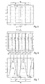
- Fig. 5 shows a diagram with an abscissa, on which the time is plotted, and an ordinate, on which an intensity present on the surface 52 is plotted.
- a first rectangular intensity profile 68 is shown.
- the intensity profile 68 has a period length with the normalized value 1.
- the intensity profile is shifted along the abscissa by a sliding distance 69.
- the sliding distance 69 includes a first period 70 and a second period 71 of the first intensity profile 68.
- the intensity profile 68 is shifted at a constant speed and is exemplified here for a period of time 72 at a particular point on the surface 52 with a one pixel resolution by the camera 38 recorded.
- the illustration shows the time during the shift, which is centered in time in the period 72.
- Fig. 6 shows a diagram with the abscissa Fig. 5 and an ordinate describing the state of the camera 38. If the state has the value 0, then the shutter of the camera 38 is closed. The image sensor is not exposed. If the value at the ordinate is 1, the shutter of the camera 38 is opened and an image is taken. Within the diagram, exposure times 74 are shown. The exposure time 74 at the reference time 0 corresponds to the period 72, so that the shutter of the camera is opened at the beginning of the period 72 and closed at the end of the period 72.
- Fig. 7 shows a diagram with the abscissa Fig. 5 , where the ordinate in Fig. 7 describes the intensity within the recorded images.
- multiple vertices 76 are shown.
- the value at the interpolation point 76 at the time 0 arises because the camera 38, due to its function during the exposure time 74, and thus during the period 72, integrates over the corresponding area of the intensity profile 68.
- the other interpolation points 76 result from the respective exposure times 74 in conjunction with the corresponding regions of the intensity profile 68.
- the interpolation points 76 define a curve 78.
- the curve 78 here runs trapezoidal and is periodic, due to the integration by the camera 38 is due.
- Curve 78 is shown here for a single camera pixel.
- An array having a plurality of pixels for capturing the images at an exposure time 74 results in an image showing as content a periodic trapezoidal virtual intensity trace 78 across the location.
- Fig. 6 By taking temporally successive pictures, as in Fig. 6 is shown, then arise images showing the shifting of the trapezoidal virtual intensity curve 78.
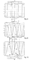
- Fig. 8 shows the diagram Fig. 5 with the intensity profile 68, the sliding distance 69 and the first and second periods 70 and 71. Within the diagram, a period 80 is marked, which is chosen substantially larger in comparison with the period 72.
- Fig. 9 shows a diagram with the abscissa Fig. 8 and an ordinate about the light intensity.
- a periodic, trapezoidal light ramp 82 is shown.
- the time period 80 corresponds to a single trapezoid of the light ramp 82.
- the exposure time 74 is selected equal to the time period 80.
- the camera thus captures a complete trapezoid of the light ramp 82 and, in addition, a substantially larger area of the intensity profile 68 than in FIG Fig. 5 the case is.
- the choice of the exposure time 74 can also be made independently of the periodicity of the characteristic 82, whereby the effective characteristic can additionally be varied.
- a shifted light ramp 82 ' which can be generated from the light ramp 82 by being displaced along an arrow 84.
- Fig. 10 shows a diagram with the abscissa and the ordinate Fig. 7 , Within the diagram, multiple vertices 86 are shown distributed over the two periods 70 and 71.
- the value at fulcrum 86 at time 0 results from the integration over the exposure time 74 in conjunction with the light ramp 82.
- the range of the intensity curve 68 within the time period 80 is integrated, with the individual values of the intensity profile 68 being weighted with the light ramp. In a corresponding manner, this is done for all interpolation points 86.
- the plurality of interpolation points 86 result in a sinusoidal curve 88.
- the characteristic is convoluted within the exposure time, in this case the one trapezoid, with the intensity profile. From this convolution, the curve 88 arises as a continuous curve.
- the curve 88 would arise when using the method, when the light ramp 82 would be moved in infinitely small steps over the intensity profile 68. Due to the real exposure time 74 required, only the discrete support points 86 lying on the curve 88 can be detected. Due to the real longer exposure time 74, the curve 88 includes fewer vertices 86 than the curve 78. It is also possible that even fewer vertices may be detected within such a curve.
- an interval the sliding distance, is considered, over which a pattern is constantly moved and over which several images are taken.
- the pattern includes first and second fringe patterns superimposed orthogonal to each other.
- the first fringe pattern has a first intensity profile with a first fringe period and the second fringe pattern has a second intensity curve with a second fringe period.
- five pictures are taken. Further assume that the interval includes exactly three first fringe periods of the first fringe pattern and four fringe periods of the second fringe pattern.
- the number of frames here violates the general sampling theorem with respect to the first fringe periods and second fringe periods. Nevertheless, the two subpatterns can be distinguished, since their aliasing frequencies, which result from subsampling, are different.
- the use of several, in this case three and four fringe periods, allows the exposure time of individual images, as in the Fig. 5 to 10 described, be chosen larger. It follows that a characteristic, here a filter function, can be broadened. In other words, the relative filter width of the filtering can be increased by extending the exposure time. In addition, a relative frequency difference between the first and second intensity profile is small here, which has an advantageous effect on an interpretation of the filtering.
- This angle offers the optimum possibility of being able to record the two intensity profiles simultaneously with an image recording unit and then be able to differentiate correctly, as described in the introduction WO 2009/007130 A1 is described.
- the disclosure of this application is incorporated herein by reference.
- a rectangular intensity curve is used for both the first and the second intensity profile, so that these intensity curves contain only odd harmonics in addition to a fundamental wave.
- the third harmonic dominates, ie the harmonic at three times the frequency of the fundamental. Therefore, two simple filter functions are combined, with the first filter function suppressing the third harmonic of the first intensity curve and the second filter function suppressing the third harmonic of the second intensity curve. This leads to a low-pass characteristic of second order and thus at the same time to a good damping of higher harmonics.
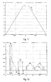
- the resulting filter function is the convolution of both simple filter functions and has a trapezoidal shape with a width:
- Fig. 11 shows a graph with an abscissa over time and an ordinate on the value of the filter function. Within the diagram is a curve 90 showing the filter function described above.
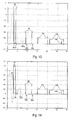
- Fig. 12 shows a diagram with an abscissa on the frequencies and an ordinate on the amplitude.
- the first intensity curve is the first Fourier-transformed intensity curve 92 and the second intensity curve is second Fourier-transformed. Intensity curve 94 shown.
- the Fourier-transformed intensity curves 92, 94 each have a fundamental wave 96, third harmonic 98, fifth harmonic 100, and seventh harmonic 102.
- the ninth harmonic 104 of the first Fourier-transformed intensity curve 92 is shown.
- a filter characteristic 106 is shown which is represented by the filter function in the form of the curve 90 in FIG Fig. 11 is generated.
- the filter characteristic 96 has two zeros 108 on the third harmonics 98 of the intensity curves 92 and 94. As a result, the third harmonics 98 are completely filtered out of the intensity curves 92 and 94.
- the higher harmonics 100, 102 and 104 are very strongly attenuated and only slightly passed by the filter characteristic 106.
- FIGS. 13 and 14 show the diagram of the Fig. 12 wherein the filter characteristic 106 has been changed by an additional subsequent digital filtering into the filter characteristics 106a and 106b.
- the filter characteristic 106a in FIG Fig. 13 has an additional zero 108 which is at the location of the fundamental wave 96 of the second intensity curve 94. It is thus achieved that not only is there a low-pass filtering of the intensity profiles 92, 94, but the second intensity profile 94 is substantially completely filtered out.
- the filter characteristic 106b is in Fig. 14 in a similar manner as the filter characteristic 106a emerged. However, the filter characteristic 106b has a further zero point 108 with respect to the filter characteristic 106. This zero point 108 is located at the position of the fundamental wave 96 of the first intensity curve 92. In this way, corresponding to the procedure in FIG Fig. 15 , the first intensity profile 92 is essentially filtered out of the images.
- Fig. 15 shows a diagram with an abscissa on the location and an ordinate on the light intensity. Within the diagram, two sine approximations 100 and 102 are shown. These sine approximations 100, 102 represent an approximation to an ideal sine, which result when the method according to the invention, as in FIGS Fig. 15 and 16 described, is applied to the in the example mentioned rectangular intensity curves 92 and 94.
- Fig. 16 shows a flowchart of a preferred method of the type according to the invention in a simplified representation.
- a step 114 first the initial position of the surface 52 is read in along its direction of movement. This can be done in a known manner with the aid of position sensors that detect the position of the surface 52.
- a step 116 a count variable i is set to zero.
- the count variable i is incremented by one.
- an image is taken.
- steps 122 and 124 are parallel.
- step 122 the considered first intensity profile 34 is shifted relative to the surface 52.
- the light intensity is varied in step 124.
- step 126 After a predetermined time or by appropriately driving the camera 38 by means of the control and evaluation unit 20, the recording is terminated in step 126.
- step 132 surface defects depending on the local surface slopes are determined, for example, by using a threshold criterion.
- an output signal is then generated which, for example, in the case of a detected surface defect, ensures that the surface point identified as defective is marked or stored in a manner.
- the sliding distance within which the plurality of images are taken corresponds, in some embodiments, to exactly one period of the intensity profile.
- each surface point to be inspected is recorded within the sliding distance at least four times, because this allows a very simple determination of the local inclination of the surface point according to the so-called 4-bucket method. This is in the aforementioned WO 2009/007130 A1 which is hereby incorporated by reference in its entirety.
- post-processing it is advantageous to post-process the images after recording. This can be done, for example, by digital filtering during evaluation of the images. In this case, a high number of images per shift distance has the advantage that a high number of harmonics can additionally be digitally filtered out. Thus, the post-processing can increase the accuracy of the intensity profile and thus the accuracy in inspecting the surface even further.
- post-processing may advantageously involve separating a plurality of superimposed intensity traces from each other as shown in FIG WO 2009/007130 A1 is explained.
- the exposure time can be adjusted based on the information about instantaneous position or instantaneous speed. This is done by using the current position or the instantaneous speed of the beginning and end of the image capture (opening of the camera shutter) are determined.
Landscapes
- Physics & Mathematics (AREA)
- General Physics & Mathematics (AREA)
- Engineering & Computer Science (AREA)
- Computer Vision & Pattern Recognition (AREA)
- Chemical & Material Sciences (AREA)
- Life Sciences & Earth Sciences (AREA)
- Health & Medical Sciences (AREA)
- Analytical Chemistry (AREA)
- Biochemistry (AREA)
- General Health & Medical Sciences (AREA)
- Immunology (AREA)
- Pathology (AREA)
- Investigating Materials By The Use Of Optical Means Adapted For Particular Applications (AREA)
Applications Claiming Priority (1)
| Application Number | Priority Date | Filing Date | Title |
|---|---|---|---|
| DE200910017465 DE102009017465B4 (de) | 2009-04-03 | 2009-04-03 | Verfahren und Vorrichtung zum optischen Inspizieren einer zumindest teilweise reflektierenden Oberfläche an einem Gegenstand |
Publications (2)
| Publication Number | Publication Date |
|---|---|
| EP2236979A2 true EP2236979A2 (fr) | 2010-10-06 |
| EP2236979A3 EP2236979A3 (fr) | 2015-12-02 |
Family
ID=42340685
Family Applications (1)
| Application Number | Title | Priority Date | Filing Date |
|---|---|---|---|
| EP10003123.6A Withdrawn EP2236979A3 (fr) | 2009-04-03 | 2010-03-24 | Procédé et dispositif d'inspection optique d'une surface au moins partiellement réfléchissante sur un objet |
Country Status (3)
| Country | Link |
|---|---|
| EP (1) | EP2236979A3 (fr) |
| JP (1) | JP5612891B2 (fr) |
| DE (1) | DE102009017465B4 (fr) |
Cited By (3)
| Publication number | Priority date | Publication date | Assignee | Title |
|---|---|---|---|---|
| EP2386848A1 (fr) * | 2010-05-11 | 2011-11-16 | Visuol Technologies | Installation de contrôle de la qualité d'une surface d'un objet |
| WO2014016001A1 (fr) * | 2012-07-25 | 2014-01-30 | Siemens Aktiengesellschaft | Codage de couleur pour mesure en trois dimensions, en particulier sur des surfaces dispersives transparentes |
| FR3101420A1 (fr) | 2019-09-30 | 2021-04-02 | Saint-Gobain Glass France | Méthode d’évaluation de la qualité optique d’une zone délimitée d’un vitrage |
Families Citing this family (2)
| Publication number | Priority date | Publication date | Assignee | Title |
|---|---|---|---|---|
| DE102014207022A1 (de) | 2014-04-11 | 2015-10-29 | Siemens Aktiengesellschaft | Tiefenbestimmung einer Oberfläche eines Prüfobjektes |
| US10753726B2 (en) | 2017-03-26 | 2020-08-25 | Cognex Corporation | System and method for 3D profile determination using model-based peak selection |
Citations (1)
| Publication number | Priority date | Publication date | Assignee | Title |
|---|---|---|---|---|
| WO2009007130A1 (fr) | 2007-07-12 | 2009-01-15 | Carl Zeiss Ag | Procédé et dispositif d'inspection optimisée d'une surface sur un objet |
Family Cites Families (7)
| Publication number | Priority date | Publication date | Assignee | Title |
|---|---|---|---|---|
| JP3054227B2 (ja) * | 1990-06-28 | 2000-06-19 | マツダ株式会社 | 表面欠陥検査装置 |
| US5336024A (en) * | 1993-02-17 | 1994-08-09 | Matsushita Electric Works, Ltd. | Precision drilling method |
| JP3201217B2 (ja) * | 1995-04-17 | 2001-08-20 | 日産自動車株式会社 | 表面欠陥検査装置 |
| JP3767201B2 (ja) * | 1998-09-18 | 2006-04-19 | オムロン株式会社 | 光式センサ |
| DE10355010A1 (de) * | 2003-11-25 | 2005-06-23 | Waliczek, Peter | Meßvorrichtung und Meßverfahren zur Erfassung von Oberflächen von 3D Objekten, mit auf einem drehenden Zylinder angebrachten Projektionsmuster |
| JP3921547B2 (ja) * | 2004-08-27 | 2007-05-30 | 国立大学法人 和歌山大学 | ラインセンサ及びライン状プロジェクタによる形状計測方法と装置 |
| DE102005038535A1 (de) * | 2005-08-16 | 2007-02-22 | Michael Probst | Rotationssymetrischer Streifenprojektor für die symetrische Ausleuchtung reflektierender Freiformflächen zur Detektierung von Oberflächenfehlern |
-
2009
- 2009-04-03 DE DE200910017465 patent/DE102009017465B4/de not_active Expired - Fee Related
-
2010
- 2010-03-24 EP EP10003123.6A patent/EP2236979A3/fr not_active Withdrawn
- 2010-04-05 JP JP2010087388A patent/JP5612891B2/ja not_active Expired - Fee Related
Patent Citations (1)
| Publication number | Priority date | Publication date | Assignee | Title |
|---|---|---|---|---|
| WO2009007130A1 (fr) | 2007-07-12 | 2009-01-15 | Carl Zeiss Ag | Procédé et dispositif d'inspection optimisée d'une surface sur un objet |
Cited By (8)
| Publication number | Priority date | Publication date | Assignee | Title |
|---|---|---|---|---|
| EP2386848A1 (fr) * | 2010-05-11 | 2011-11-16 | Visuol Technologies | Installation de contrôle de la qualité d'une surface d'un objet |
| FR2960060A1 (fr) * | 2010-05-11 | 2011-11-18 | Visuol Technologies | Installation de controle de la qualite d'une surface d'un objet |
| FR2960059A1 (fr) * | 2010-05-11 | 2011-11-18 | Visuol Technologies | Installation de controle de la qualite d'une surface d'un objet |
| WO2014016001A1 (fr) * | 2012-07-25 | 2014-01-30 | Siemens Aktiengesellschaft | Codage de couleur pour mesure en trois dimensions, en particulier sur des surfaces dispersives transparentes |
| US9404741B2 (en) | 2012-07-25 | 2016-08-02 | Siemens Aktiengesellschaft | Color coding for 3D measurement, more particularly for transparent scattering surfaces |
| FR3101420A1 (fr) | 2019-09-30 | 2021-04-02 | Saint-Gobain Glass France | Méthode d’évaluation de la qualité optique d’une zone délimitée d’un vitrage |
| WO2021063847A1 (fr) | 2019-09-30 | 2021-04-08 | Saint-Gobain Glass France | Méthode d'évaluation de la qualité optique d'une zone délimitée d'un vitrage |
| US12130244B2 (en) | 2019-09-30 | 2024-10-29 | Saint-Gobain Glass France | Method for evaluating the optical quality of a delineated region of a glazing |
Also Published As
| Publication number | Publication date |
|---|---|
| JP2010243496A (ja) | 2010-10-28 |
| DE102009017465B4 (de) | 2011-02-17 |
| JP5612891B2 (ja) | 2014-10-22 |
| DE102009017465A1 (de) | 2010-10-07 |
| EP2236979A3 (fr) | 2015-12-02 |
Similar Documents
| Publication | Publication Date | Title |
|---|---|---|
| EP1697061B1 (fr) | Procede pour reconnaitre une structure a appliquer sur un substrat, au moyen de plusieurs cameras, et dispositif a cet effet | |
| EP3479058B1 (fr) | Procédé et dispositif servant à mesurer des dommages subis par une carrosserie | |
| EP3278302B1 (fr) | Système de mesure de déplacement d'une machine et procédé de fonctionnement du système de mesure de déplacement | |
| EP0228500B2 (fr) | Méthode et dispositif pour la mesure sans contact du profil d'une roue des roues d'ensembles de roues de voie ferrée | |
| DE102008015499B4 (de) | Verfahren und Vorrichtung zur Bestimmung der 3D-Koordinaten eines Objekts | |
| EP2710794A2 (fr) | Procédé pour produire et évaluer une image | |
| EP2167948A1 (fr) | Procédé et dispositif d'inspection optimisée d'une surface sur un objet | |
| EP2589926B1 (fr) | Dispositif et procédé de mesure optique de la forme d'un objet mobile | |
| WO2007065704A1 (fr) | Dispositif et procede pour realiser des mesures a la surface d'un corps | |
| WO2015169730A1 (fr) | Procédé et capteur servant à déterminer la surface d'un objet par déflectométrie | |
| DE102009017465B4 (de) | Verfahren und Vorrichtung zum optischen Inspizieren einer zumindest teilweise reflektierenden Oberfläche an einem Gegenstand | |
| EP3433577A1 (fr) | Dispositif et procédé pour combiner des signaux de mesure à partir de signaux d'éclairage | |
| DE102010017604B4 (de) | Verfahren zum optischen Messen von Strukturen eines Objekts | |
| WO2021204521A1 (fr) | Procédé et dispositif d'inspection pour l'inspection optique d'une surface | |
| EP4133234B1 (fr) | Dispositif et procédé de mesure optique pour déterminer la forme tridimensionnelle d'un objet | |
| WO2017037248A1 (fr) | Procédé de mesure par filtre spatial et dispositif de mesure par filtre spatial | |
| EP2221609A2 (fr) | Procédé et dispositif d'inspection optique d'une surface sur un objet | |
| DE10303282B4 (de) | Verfahren zur Inline-Qualitätsprüfung und zum Authentizitätsnachweis von bedruckten und/oder geprägten bahnförmigen Materialien | |
| AT520351B1 (de) | Freiformflächeninspektion mit schaltbarer Lichtquelle | |
| DE102022125409A1 (de) | Verfahren und Vorrichtung zur Aufnahme mehrerer Abbildungen eines Objekts mit unterschiedlichen Beleuchtungskonfigurationen | |
| DE102022116317A1 (de) | Verfahren zur Detektion einer Verschmutzung auf einer Kamera eines Fahrzeugs, Kamera und Fahrerassistenzsystem | |
| DE2623578C2 (de) | Vorrichtung zur automatischen Bestimmung der Größe und Anzahl von Teilchen in einem Teilchenfeld | |
| EP2799847A1 (fr) | Procédé de contrôle optique de surfaces d'objets | |
| DE3010559C2 (de) | Einrichtungen zur Feststellung von Fehlern in regelmäßigen Mustern | |
| EP2237026A1 (fr) | Dispositif pour l'inspection optique d'une surface sur un objet |
Legal Events
| Date | Code | Title | Description |
|---|---|---|---|
| PUAI | Public reference made under article 153(3) epc to a published international application that has entered the european phase |
Free format text: ORIGINAL CODE: 0009012 |
|
| AK | Designated contracting states |
Kind code of ref document: A2 Designated state(s): AT BE BG CH CY CZ DE DK EE ES FI FR GB GR HR HU IE IS IT LI LT LU LV MC MK MT NL NO PL PT RO SE SI SK SM TR |
|
| AX | Request for extension of the european patent |
Extension state: AL BA ME RS |
|
| PUAL | Search report despatched |
Free format text: ORIGINAL CODE: 0009013 |
|
| AK | Designated contracting states |
Kind code of ref document: A3 Designated state(s): AT BE BG CH CY CZ DE DK EE ES FI FR GB GR HR HU IE IS IT LI LT LU LV MC MK MT NL NO PL PT RO SE SI SK SM TR |
|
| AX | Request for extension of the european patent |
Extension state: AL BA ME RS |
|
| RIC1 | Information provided on ipc code assigned before grant |
Ipc: G01B 11/25 20060101AFI20151028BHEP Ipc: G01N 21/88 20060101ALI20151028BHEP |
|
| GRAP | Despatch of communication of intention to grant a patent |
Free format text: ORIGINAL CODE: EPIDOSNIGR1 |
|
| 17P | Request for examination filed |
Effective date: 20160601 |
|
| RBV | Designated contracting states (corrected) |
Designated state(s): AT BE BG CH CY CZ DE DK EE ES FI FR GB GR HR HU IE IS IT LI LT LU LV MC MK MT NL NO PL PT RO SE SI SK SM TR |
|
| INTG | Intention to grant announced |
Effective date: 20160712 |
|
| GRAS | Grant fee paid |
Free format text: ORIGINAL CODE: EPIDOSNIGR3 |
|
| STAA | Information on the status of an ep patent application or granted ep patent |
Free format text: STATUS: GRANT OF PATENT IS INTENDED |
|
| STAA | Information on the status of an ep patent application or granted ep patent |
Free format text: STATUS: THE APPLICATION IS DEEMED TO BE WITHDRAWN |
|
| 18D | Application deemed to be withdrawn |
Effective date: 20161123 |