EP2237015A2 - Appareil de mesure de concentration de matières particulières - Google Patents
Appareil de mesure de concentration de matières particulières Download PDFInfo
- Publication number
- EP2237015A2 EP2237015A2 EP09014750A EP09014750A EP2237015A2 EP 2237015 A2 EP2237015 A2 EP 2237015A2 EP 09014750 A EP09014750 A EP 09014750A EP 09014750 A EP09014750 A EP 09014750A EP 2237015 A2 EP2237015 A2 EP 2237015A2
- Authority
- EP
- European Patent Office
- Prior art keywords
- particulate matter
- exhaust gas
- filter
- detection filter
- matter detection
- Prior art date
- Legal status (The legal status is an assumption and is not a legal conclusion. Google has not performed a legal analysis and makes no representation as to the accuracy of the status listed.)
- Withdrawn
Links
Images






Classifications
-
- G—PHYSICS
- G01—MEASURING; TESTING
- G01N—INVESTIGATING OR ANALYSING MATERIALS BY DETERMINING THEIR CHEMICAL OR PHYSICAL PROPERTIES
- G01N15/00—Investigating characteristics of particles; Investigating permeability, pore-volume or surface-area of porous materials
- G01N15/06—Investigating concentration of particle suspensions
- G01N15/0606—Investigating concentration of particle suspensions by collecting particles on a support
- G01N15/0618—Investigating concentration of particle suspensions by collecting particles on a support of the filter type
-
- F—MECHANICAL ENGINEERING; LIGHTING; HEATING; WEAPONS; BLASTING
- F01—MACHINES OR ENGINES IN GENERAL; ENGINE PLANTS IN GENERAL; STEAM ENGINES
- F01N—GAS-FLOW SILENCERS OR EXHAUST APPARATUS FOR MACHINES OR ENGINES IN GENERAL; GAS-FLOW SILENCERS OR EXHAUST APPARATUS FOR INTERNAL-COMBUSTION ENGINES
- F01N13/00—Exhaust or silencing apparatus characterised by constructional features
- F01N13/009—Exhaust or silencing apparatus characterised by constructional features having two or more separate purifying devices arranged in series
- F01N13/0093—Exhaust or silencing apparatus characterised by constructional features having two or more separate purifying devices arranged in series the purifying devices are of the same type
-
- F—MECHANICAL ENGINEERING; LIGHTING; HEATING; WEAPONS; BLASTING
- F01—MACHINES OR ENGINES IN GENERAL; ENGINE PLANTS IN GENERAL; STEAM ENGINES
- F01N—GAS-FLOW SILENCERS OR EXHAUST APPARATUS FOR MACHINES OR ENGINES IN GENERAL; GAS-FLOW SILENCERS OR EXHAUST APPARATUS FOR INTERNAL-COMBUSTION ENGINES
- F01N2560/00—Exhaust systems with means for detecting or measuring exhaust gas components or characteristics
- F01N2560/05—Exhaust systems with means for detecting or measuring exhaust gas components or characteristics the means being a particulate sensor
-
- F—MECHANICAL ENGINEERING; LIGHTING; HEATING; WEAPONS; BLASTING
- F01—MACHINES OR ENGINES IN GENERAL; ENGINE PLANTS IN GENERAL; STEAM ENGINES
- F01N—GAS-FLOW SILENCERS OR EXHAUST APPARATUS FOR MACHINES OR ENGINES IN GENERAL; GAS-FLOW SILENCERS OR EXHAUST APPARATUS FOR INTERNAL-COMBUSTION ENGINES
- F01N2560/00—Exhaust systems with means for detecting or measuring exhaust gas components or characteristics
- F01N2560/07—Exhaust systems with means for detecting or measuring exhaust gas components or characteristics the means being an exhaust gas flow rate or velocity meter or sensor, intake flow meters only when exclusively used to determine exhaust gas parameters
-
- F—MECHANICAL ENGINEERING; LIGHTING; HEATING; WEAPONS; BLASTING
- F01—MACHINES OR ENGINES IN GENERAL; ENGINE PLANTS IN GENERAL; STEAM ENGINES
- F01N—GAS-FLOW SILENCERS OR EXHAUST APPARATUS FOR MACHINES OR ENGINES IN GENERAL; GAS-FLOW SILENCERS OR EXHAUST APPARATUS FOR INTERNAL-COMBUSTION ENGINES
- F01N2560/00—Exhaust systems with means for detecting or measuring exhaust gas components or characteristics
- F01N2560/08—Exhaust systems with means for detecting or measuring exhaust gas components or characteristics the means being a pressure sensor
-
- F—MECHANICAL ENGINEERING; LIGHTING; HEATING; WEAPONS; BLASTING
- F01—MACHINES OR ENGINES IN GENERAL; ENGINE PLANTS IN GENERAL; STEAM ENGINES
- F01N—GAS-FLOW SILENCERS OR EXHAUST APPARATUS FOR MACHINES OR ENGINES IN GENERAL; GAS-FLOW SILENCERS OR EXHAUST APPARATUS FOR INTERNAL-COMBUSTION ENGINES
- F01N3/00—Exhaust or silencing apparatus having means for purifying, rendering innocuous, or otherwise treating exhaust
- F01N3/02—Exhaust or silencing apparatus having means for purifying, rendering innocuous, or otherwise treating exhaust for cooling, or for removing solid constituents of, exhaust
- F01N3/021—Exhaust or silencing apparatus having means for purifying, rendering innocuous, or otherwise treating exhaust for cooling, or for removing solid constituents of, exhaust by means of filters
-
- F—MECHANICAL ENGINEERING; LIGHTING; HEATING; WEAPONS; BLASTING
- F01—MACHINES OR ENGINES IN GENERAL; ENGINE PLANTS IN GENERAL; STEAM ENGINES
- F01N—GAS-FLOW SILENCERS OR EXHAUST APPARATUS FOR MACHINES OR ENGINES IN GENERAL; GAS-FLOW SILENCERS OR EXHAUST APPARATUS FOR INTERNAL-COMBUSTION ENGINES
- F01N3/00—Exhaust or silencing apparatus having means for purifying, rendering innocuous, or otherwise treating exhaust
- F01N3/02—Exhaust or silencing apparatus having means for purifying, rendering innocuous, or otherwise treating exhaust for cooling, or for removing solid constituents of, exhaust
- F01N3/021—Exhaust or silencing apparatus having means for purifying, rendering innocuous, or otherwise treating exhaust for cooling, or for removing solid constituents of, exhaust by means of filters
- F01N3/031—Exhaust or silencing apparatus having means for purifying, rendering innocuous, or otherwise treating exhaust for cooling, or for removing solid constituents of, exhaust by means of filters having means for by-passing filters, e.g. when clogged or during cold engine start
Definitions
- the present invention relates to a technical field of exhaust gas purification of an internal combustion engine, and more particularly to a particulate matter concentration measuring apparatus for measuring the concentration of particulate matter included in exhaust gas from a diesel engine.
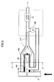
- FIG. 1 shows a known particulate matter concentration measuring apparatus 20PM (PM sensor), as described in Patent Document 1, capable of detecting the concentration of particulate matter (PM) including carbon (C) as a main component in exhaust gas of a diesel engine.
- the particulate matter concentration measuring apparatus 20PM includes an exhaust line 21, a secondary exhaust line 21A branching from the exhaust line 21, a particulate matter detection filter 22A provided in the secondary exhaust line 21A, and a differential pressure sensor 22B measuring differential pressure between inlet and outlet of the particulate matter detection filter 22A.
- a flow rate meter 24 and a temperature sensor T1 are provided in the particulate matter detection filter 22A.
- a heater 22H is provided in the particulate matter detection filter 22A.
- a differential pressure ⁇ P across the particulate matter detection filter 22A, a temperature T of exhaust gas in the secondary exhaust line 21A, and a flow amount Q2 of exhaust gas in the secondary exhaust line 21A are measured. Then, based on the measured values of the differential pressure ⁇ P, the temperature T of the exhaust gas, and the flow amount Q2 of the exhaust gas, a value of PM [g/h] which is the mass of particulate matter collected on the particulate matter detection filter 22A per unit time is calculated.
- a value of PM conc [g/cm 3 ] which is the concentration of particulate matter (PM) in the exhaust gas is calculated.
- PM conc [g/cm 3 ] which is the concentration of particulate matter (PM) in the exhaust gas.
- a heater 22H is provided so as to burn and remove particulate matter (PM) when the particulate matter (PM) is accumulated on the particulate matter detection filter 22A to some extent.
- Patent Document 1 discloses a Diesel Particulate Filter (DPF) 22 made of porous ceramic material and provided in the exhaust line 21 of an exhaust gas purification apparatus 20. Further, the secondary exhaust line 21A is connected to the exhaust line 21 on the upstream side of the Diesel Particulate Filter (DPF) 22, and based on a value of PM conc [g/m 3 ] which is concentration of particulate matter (PM) in exhaust gas and an engine operating status or a flow amount Q1 of the exhaust gas introduced into the Diesel Particulate Filter (DPF) 22, a value of PM enter full filter [g/h] which is the mass of particulate matter (PM) introduced into the Diesel Particulate Filter (DPF) 22 is calculated.
- PM conc [g/m 3 ] which is concentration of particulate matter (PM) in exhaust gas and an engine operating status or a flow amount Q1 of the exhaust gas introduced into the Diesel Particulate Filter (DPF) 22
- PM enter full filter [g/h] which is the mass of particulate matter (
- the collected particulate matter (PM) is likely to be gradually accumulated with continuous use of the Diesel Particulate Filter (DPF) 22. If the accumulation of the particulate matter (PM) in the Diesel Particulate Filter (DPF) 22 is ignored, a pressure caused by exhaust gas may become too high, which may lower fuel economy and/or cause engine damage.
- the accumulated particulate matter (PM) is burned and removed at regular intervals in the Diesel Particulate Filter (DPF) 22 so as to regenerate the Diesel Particulate Filter (DPF) 22.
- Diesel Particulate Filter (DPF) 22 To regenerate the Diesel Particulate Filter (DPF) 22, high-temperature exhaust gas is introduced into the Diesel Particulate Filter (DPF) 22 so that the accumulated particulate matter (PM) can be burned and removed.
- PM accumulated particulate matter
- Patent Document 1 by obtaining the value of PM enter full filter [g/h] which is the mass of particulate matter (PM) collected on the Diesel Particulate Filter (DPF) 22, it becomes possible to accurately determine whether an amount of particulate matter (PM) having been actually collected on the Diesel Particulate Filter (DPF) 22 exceeds a predetermined threshold value which necessitates the regeneration of the Diesel Particulate Filter (DPF) 22.
- Patent Document 1 EP1916394A1
- a particulate matter concentration measuring apparatus capable of measuring concentration of particulate matter in exhaust gas passing through an exhaust line (21) of a diesel engine.
- the particulate matter concentration measuring apparatus (40PM) includes an exhaust gas collecting line (41A) branched from the exhaust line (21) and having a cross-sectional area smaller than that of the exhaust line (21), a particulate matter detection filter (42A) provided in the exhaust gas collecting line (41A), a differential pressure sensor (42B) sensing differential pressure between inlet and outlet of the particulate matter detection filter (42A), a passage wall (42E) disposed so that exhaust gas flows to a downstream side of the particulate matter detection filter (42A), a unit including an inlet side passage (42a) through which exhaust gas passes, the exhaust gas having passed through the inlet side passage (42a) flowing into the particulate matter detection filter (42A), and a unit including an outlet side passage (42s) though which the exhaust gas having passed through the part
- outlet side passage (42s) defines a space having a cross-sectional area 1.0 times or more larger than a cross-sectional area of a space defined by the inlet side passage (42a), the cross-sectional areas being substantially perpendicular to a longitudinal axis of the particulate matter detection filter (42A).
- exhaust gas having passed through the particulate matter detection filter may flow to the downstream side without being left or held and as a result, it may become possible to accurately measure the differential pressure and accordingly, the concentration of particulate matter (PM) may be more accurately measured.
- FIG. 2 shows an exemplary configuration of a particulate matter concentration measuring apparatus 40PM according to a first embodiment of the present invention.
- the same reference numerals are used for the same or equivalent elements described above and the descriptions thereof may be omitted.
- the particulate matter concentration measuring apparatus 40PM (PM sensor) of FIG. 2 in a case where a problem occurs in the Diesel Particulate Filter (DPF) 22 and a larger amount of particulate matter (PM) than a predetermined threshold value leaks into the downstream side of the Diesel Particulate Filter (DPF) 22 in the exhaust line 21, the problem can be detected so as to flash or turn on an alarm or a lamp and the like.
- an exhaust gas collecting line 41A having an exhaust gas collection section 41a on one end thereof and there is also provided the Diesel Particulate Filter (DPF) 22 in the exhaust line 21 from a diesel engine, so that the exhaust gas collecting line 41A is connected to the exhaust line 21 on the downstream side of the Diesel Particulate Filter (DPF) 22.
- a particulate matter detection filter 42A illustrated in detail in FIG. 3 and a flow meter 44 are connected in series.
- the exhaust gas collecting line 41A is connected to a negative-pressure tank, an air intake section or the like where pressure is lower than that at the inlet of the particulate matter detection filter 42A, so that exhaust gas in the exhaust line 21 is drawn into the particulate matter detection filter 42A.
- This provides the same effect as that obtained by connecting a suction pump on the downstream side of the exhaust gas collecting line 41A, which makes it possible to reliably supply exhaust gas to the particulate matter detection filter 42A.
- a temperature sensor T1 for measuring temperature of the particulate matter detection filter 42A and a differential pressure sensor 42B for measuring differential pressure across the particulate matter detection filter 42A.
- the size of a flow passage cross-sectional area of the exhaust gas collection section 41a is smaller than that of the exhaust line 21.
- a known manometer such as a diaphram gauge, a strain-gauge-type, Bellows-type, or thermal-type manometer may be used.
- a known flow meter such as a hot wire flow meter, a venturi flow meter may be used.
- FIG. 3 shows an exemplary configuration of the particulate matter detection filter 42A.
- the particulate matter detection filter 42A has a single cell 42b only.
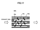
- the particulate matter detection filter 42A may be formed by stacking plural cells 42b as shown in FIG. 17 .
- a total volume of one or plural gas passages 42a of the particulate matter detection filter 42A is set to be equal to or less than 5% (e.g., in a range from 0.05% to 5%) of the total volume of the exhaust gas passage in the Diesel Particulate Filter (DPF) 22 or equal to or less than 65 ml (e.g., in a range from 0.05 ml to 65 ml) or the filtration area of one or plural gas passages 42a (see FIG. 3 ) of the particulate matter detection filter 42A is set in a range from 0.1 cm 2 to 1,000 cm 2 (preferably in a range from 1 cm 2 to 10 cm 2 ).
- the gas passage 42a is formed so as to have a rectangular cross-sectional shape or the like and one end thereof being closed (in this example of this embodiment, the rear (right-hand) side of the gas passage 42a is closed as shown in FIG.3 ).
- each cell 42b formed of porous ceramic material has an inflow-side gas passage 42a formed by closing one end of the cell 42b and leaving the other end open, so that exhaust gas introduced into the inflow-side gas passage 42a passes through the cell wall made of porous ceramic material to flow into an adjoining inflow-side gas passage 42a.
- particulate matter (PM) is trapped (collected) on an inner wall surface of the cell 42b, so that a particulate matter layer 42c is formed on the inner wall surface of the cell 42b.
- FIG. 4 shows a modification (modified example) of the cell 42b in FIG. 3 .
- exhaust gas passes through the cell wall of the cell 42b from the inflow-side gas passage which is outside of the cell 42b and flows into the outflow-side gas passage 42a (see FIG. 4 ) formed inside the cell 42b, so that the deposition of the particulate matter layer 42c is formed on the outer wall surface of the cell 42b.
- the particulate matter detection filter 42A is formed by, for example, alternately stacking the cell 42b in FIG. 3 and the cell 42b in FIG. 4 .
- the cells having a similar configuration shown in FIG. 17 may be formed in the Diesel Particulate Filter (DPF) 22 described with reference to FIG. 1 .
- DPF Diesel Particulate Filter
- the size and/or the cross-sectional shape of gas passage of the particulate matter detection filter 42A are substantially the same as those of the Diesel Particulate Filter (DPF) 22.
- the cross-sectional shape of gas passage of the particulate matter detection filter 42A may be any sectional shape such as a circular shape, square shape, octagon shape, elliptic shape.
- the porous ceramic material of the cell of the particulate matter detection filter 42A is substantially the same as that of the Diesel Particulate Filter (DPF) 22.
- the material of the cell of the particulate matter detection filter 42A may be material other than ceramic.
- the total volume of one or plural gas passages 42a of the particulate matter detection filter 42A is set to be equal to or less than 5% (e.g., in a range from 0.05% to 5%) of the total volume of the exhaust gas passage in the Diesel Particulate Filter (DPF) 22 or equal to or less than 65 ml (e.g., in a range from 0.05 ml to 65 ml) or the filtration area of one or plural gas passage 42a of the particulate matter detection filter 42A is set in a range from 0.1 cm 2 to 1,000 cm 2 (preferably in a range from 1 cm 2 to 10 cm 2 ), it may become possible to provide a uniform deposition of the particulate matter layer 42c on the surface of the cell 42b; thereby enabling simple and accurate measurement of accumulation amount of particulate matter (PM) in the Diesel Particulate Filter (DPF) 22.
- 5% e.g.
- ⁇ P denotes the differential pressure expressed in [Pa]
- the symbol “ ⁇ ” denotes the kinetic viscosity coefficient expressed in [Pa ⁇ s]
- the symbol “Q” denotes the flow rate of exhaust gas expressed in [m 3 /h]
- the symbol “ ⁇ ” denotes the length of a side of the cell expressed
- the particulate matter concentration measuring apparatus 40PM on the downstream side of the Diesel Particulate Filter (DPF) 22, in a case where a problem occurs in the Diesel Particulate Filter (DPF) 22 and a larger amount of particulate matter (PM) than a predetermined threshold value leaks into the downstream side of the Diesel Particulate Filter (DPF) 22 in the exhaust line 21, the problem may be immediately detected so as to flash or turn on an alarm or a lamp and the like.
- FIG. 5 shows a more detailed exemplary configuration of the particulate matter concentration measuring apparatus 40PM in FIG. 2 .
- the particulate matter detection filter 42A includes the exhaust gas collection section 41a formed on one end of the particulate matter detection filter 42A and is housed inside a housing 42E defining the exhaust gas collecting line 41A.
- the differential pressure sensor 42B which may be a diaphram gauge, is provided on the downstream side of the particulate matter detection filter 42A.
- One end of the differential pressure sensor 42B is connected to the upstream side of the particulate matter detection filter 42A, and the other side of the differential pressure sensor 42B is connected to the exhaust gas collecting line 41A on the downstream side of the particulate matter detection filter 42A.
- the differential pressure sensor 42B can measure the differential pressure across the cell 42b of the particulate matter detection filter 42A.
- FIG. 6 shows a partial cross-sectional view of the particulate matter concentration measuring apparatus 40PM with the housing 42E along A-A' line in FIG. 5 .
- exhaust gas introduced into the gas passage 42a passes through the cell 42b of the particulate matter detection filter 42A, flows into a space 42s defined between the particulate matter detection filter 42A and the housing 42E, and further flows to the downstream side of the exhaust gas collecting line 41A.
- the inner diameter (inner circumference) of the housing 42E may be accordingly decreased.
- the outer space of the cell 42b between the outer surface of the cell 42b and the inner surface of housing 42E i.e., the space 42s between the outer surface of the cell 42b and the passage wall facing the cell 42b and defining the passage of exhaust gas, may become narrower.
- the cell 42b is disposed in a free space as shown in FIG.
- the size of the total cross-sectional area of the outer space 42s is decreased; therefore, a value detected by the differential pressure sensor 42B may be more influenced by a factor other than soot deposited in the particulate matter detection filter 42A.
- the value of "PM conc [g/m 3 ]" i.e., the concentration of the particulate matter (PM) in exhaust gas
- the inventors of the present invention have studied the behavior of the measurement error by comparing the values of the concentration of the particulate matter (PM) in exhaust gas based on the above formulas (1) through (3) with the corresponding true values by changing the values of the parameters which are the internal diameter "d o " of the housing 42E, the length of a side “a o " in the rectangular cross-section at the inlet side of the cell 42b, and the wall thickness "t" of the cell 42b as shown in FIG. 8 .
- the measurement error is obtained by assuming that the measured value of the particulate matter (PM) in the exhaust line 21 of the configuration of FIG. 2 (described below) is regarded as the true value and by comparing the difference between the true value and the value of the concentration of the particulate matter (PM) in exhaust gas based on the above formulas (1) through (3).
- exhaust gas exhausted from a diesel engine 11 into the exhaust line 21 is introduced into a dilution tunnel 111 to which clean air also is being introduced to dilute and cool the exhaust gas to a temperature equal to or less than 52°C. Then the cooled exhaust gas is collected on a primary collection filer 115 and a secondary collection filter 116, so that the mass of the filters with collected particulate matter (PM) is measured using a microbalance to directly measure the amount of particulate matter (PM) in the exhaust gas. Then, the measured amount of the particulate matter (PM) is converted into the value of the concentration of the exhaust gas in the exhaust line 21 and the obtained value is defined as the true value.
- the measurement error is obtained by comparing the true value with the calculated value of "PM conc [g/m 3 ]" of the particulate matter concentration measuring apparatus 40PM (distance between diesel engine (E/G) and particulate matter concentration measuring apparatus 40 PM is 1.5 m to 2.0 m) provided in the same exhaust line 21.
- PM conc [g/m 3 ] distance between diesel engine (E/G) and particulate matter concentration measuring apparatus 40 PM is 1.5 m to 2.0 m
- Table 1 shows the measurement errors between the calculation values and true values of the concentration of particulate matter (PNM) obtained as described above in examples 1 through 7 and comparative examples 1 through 3 which vary depending on the values of the parameters described above.
- comparative examples differ from examples in that the measurement error exceeds 10%.
- FIG. 10 shows the relationships between the Area ratios and the Measurement errors in Table 1.
- the measurement error of the particulate matter concentration measuring apparatus 40PM varies mainly depending on the Area ratio and abruptly becomes worse more than 10% when the Area ratio is reduced to less than 1.0.
- the reason of the increase of the measurement error is considered that when the Area ratio is reduced to less than 1.0, the volume between the housing 42E and the cell 42b is reduced, which suggests that a factor other than soot deposited in the particulate matter detection filter 42A influences the measurement of the differential pressure.
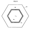
- the Area ratio of the cross-section perpendicular to a central axis "c" (extending in the longitudinal direction of the cell 42b at the center of the cross section perpendicular to the longitudinal direction of the cell 42b as shown in, for example, FIG. 12 ) be equal to or more than 1.0, preferably equal to or more than 1.5.
- the central axis "c" of the cell 42b is substantially equal to the central axis of the housing 42E.
- the Area ratio to a value equal to or more than 1.0, preferably equal to or more than 1.5, it may becomes possible to effectively reduce the influence of a factor other than soot deposited in the particulate matter detection filter 42A on the value detected by the differential pressure sensor 42B.
- the cell 42b including the exhaust gas collection section 41a in the center portion on one end of the cell 42b is formed so that the shape of the cross-sectional areas of the cell 42b and the opening of the exhaust gas collection section 41a is a rectangular shape, the cross-sectional area being perpendicular to the central axis "c".
- the cross-sectional shape along the inner surface of the housing 42E is circular shape.
- the cross-sectional shape along the outer surface of the housing 42E may be any shape so as to match the design of a vehicle in which the particulate matter concentration measuring apparatus 40PM is used.
- the present invention also includes such configuration as shown in FIG. 11 .
- the dotted line 42V defines a virtual space having the same central axis as the central axis "c" of the cell 42b and the shape similar to that of the cell 42b.
- the cross-sectional shape of the cell 42b may be any polygonal shape such as a pentagon, hexagon.
- the cross-sectional shape of the housing 42E may be the similar shape corresponding to the cross-sectional shape of the cell 42b.
- the cross-sectional shape of the cell 42b and the housing 42E is circular shape to provide smoother flow of exhaust gas.
- the same reference numerals are used for the same or equivalent elements described above and the descriptions thereof may be omitted.
- an upper limit of the Area ratio is considered below. From the viewpoint of the flow of exhaust gas passed through the cell 42b, no theoretical upper limit is placed. However, there may be some cases where a heater 42h is provided on the outer surface of the cell 42b to regenerate the cell 42b as described in the following embodiment of the present invention. In this case, when the Area ratio is too large, even if the heater 42h is driven to regenerate the cell 42b, the heat from the heater 42h may be irradiated to the outer space 42s; and as a result, the desired increase in temperature of the cell 42b may not be achieved. From this point of view, preferably, the Area ratio does not exceed 10.0.
- FIG. 14 shows an exemplary appearance of a particulate matter concentration measuring apparatus 40PM according to this embodiment of the present invention.
- the particulate matter concentration measuring apparatus 40PM includes the housing 42E having a pipe (tube) shape and made of heat-resistant metal such as stainless, and a header 42e provided on one end of the housing 42E so as to be inserted into and fixed to the exhaust line 21 shown in FIG. 2 on the downstream side of the Diesel Particulate Filter (DPF) 22.
- the particulate matter detection filter 42A made of porous ceramic material such as, preferably, Silicon Carbide (SiC).
- the header 42e constitutes the exhaust gas collecting line 41A to be inserted into the exhaust line 21.
- a flexible hose 42 is extended to the downstream end where there is provided a flow rate control unit 42G storing (housing) the differential pressure sensor 42B and the flow meter 44. Exhaust gas passed through the control unit 42G is exhausted into an exhaust tube 42g.
- the desired particulate matter concentration measuring apparatus may become smaller; therefore, it may become easier to install the particulate matter concentration measuring apparatus at a desired place in a vehicle on an as-needed basis.
- a pump 42P may be connected to the exhaust tube 42g for exhausting exhaust gas from the flow rate control unit 42G so that the exhaust gas can be forcibly exhausted.
- exhaust gas can be suctioned into the particulate matter concentration measuring apparatus and the desired particulate matter concentration measurement can be performed even in an atmosphere where there is no flow of exhaust gas through the header 42e.
- FIG. 16 shows another exemplary configuration of an exhaust gas purification apparatus 60 for purifying exhaust gas from a diesel engine, the exhaust gas purification apparatus 60 including a particulate matter concentration measuring apparatus 60PM (PM sensor).
- PM particulate matter concentration measuring apparatus
- the exhaust gas purification apparatus 60 has a similar configuration to that of the exhaust gas purification apparatus 20 in FIG. 1 in that there is the exhaust gas collecting line 41A having the exhaust gas collection section 41a connected to the exhaust line 21 on the upstream side of the Diesel Particulate Filter (DPF) 22.
- DPF Diesel Particulate Filter
- exhaust gas not having been passed through the Diesel Particulate Filter (DPF) 22 is collected by the particulate matter detection filter 42A, and based on the amount of particulate matter (PM) collected by the particulate matter detection filter 42A, in addition to the calculations according to formulas (1) through (3), the process described below is performed.
- DPF Diesel Particulate Filter
- PM conc [g/m 3 ] i.e., the concentration of the particulate matter (PM) in exhaust gas in the exhaust gas collecting line 41A
- a value of "PM enter full filter [g/h]” which is an amount of particulate matter (PM) passing through the exhaust line 21 is obtained according to the following formula (4):
- PM enter full filter g / h PM conc g / m 3 ⁇ Q ⁇ 1 m 3 / h
- the symbol “Q1” denotes the flow amount of exhaust gas passing through the Diesel Particulate Filter (DPF) 22.
- the value of "Q1" may be directly measured or may be estimated based on the engine operation state.
- valve 43 in the exhaust gas collecting line 41A, and same as the case of the valve 23 of the particulate matter concentration measuring apparatus 20PM of FIG. 1 , the valve 43 may be controlled by the flow meter 44 so that the flow amount of exhaust gas in the exhaust gas collecting line 41A is maintained at a predetermined value "Q2".
- particulate matter (PM) is gradually deposited on the particulate matter detection filter 42A (cell 42b); therefore, the particulate matter detection filter 42A is to be regenerated.
- the heater 42h on the particulate matter detection filter 42A (cell 42b).
- the heat from the heater 42h burns and removes the particulate matter (PM) including Carbon (C) as a main component and collected on the cell 42b so as to regenerate the particulate matter detection filter 42A.
- the present invention is described above by referring to preferable embodiments.
- the present invention is not limited to the specific embodiments, and within the scope of the appended claims, various modifications, transformations, alteration, exchanges, and the like may be made without departing from the scope and spirit of the present invention.
- the flow rate meter 44 may be removed, provided that the flow rate of exhaust gas passing through the exhaust gas collecting line 41A is known.
- the temperature sensor T1 may also be removed, provided that characteristic of exhaust gas is assumed to be constant.
- the heater 42h may also be removed provided that the regeneration process is not necessary.
- the valve 43 may also be removed when the flow rate is being accurately measured.
- the heater 42h used in the second embodiment of the present invention may also be used in the particulate matter concentration measuring apparatus in the first embodiment of the present invention.
Landscapes
- Chemical & Material Sciences (AREA)
- Engineering & Computer Science (AREA)
- Life Sciences & Earth Sciences (AREA)
- Analytical Chemistry (AREA)
- General Engineering & Computer Science (AREA)
- Dispersion Chemistry (AREA)
- Physics & Mathematics (AREA)
- Health & Medical Sciences (AREA)
- Combustion & Propulsion (AREA)
- Mechanical Engineering (AREA)
- Biochemistry (AREA)
- General Health & Medical Sciences (AREA)
- General Physics & Mathematics (AREA)
- Immunology (AREA)
- Pathology (AREA)
- Processes For Solid Components From Exhaust (AREA)
- Sampling And Sample Adjustment (AREA)
Applications Claiming Priority (1)
| Application Number | Priority Date | Filing Date | Title |
|---|---|---|---|
| PCT/JP2009/056750 WO2010113295A1 (fr) | 2009-03-31 | 2009-03-31 | Dispositif de mesure de la concentration d'une matière particulaire |
Publications (2)
| Publication Number | Publication Date |
|---|---|
| EP2237015A2 true EP2237015A2 (fr) | 2010-10-06 |
| EP2237015A3 EP2237015A3 (fr) | 2015-07-15 |
Family
ID=41506440
Family Applications (1)
| Application Number | Title | Priority Date | Filing Date |
|---|---|---|---|
| EP09014750.5A Withdrawn EP2237015A3 (fr) | 2009-03-31 | 2009-11-26 | Appareil de mesure de concentration de matières particulières |
Country Status (3)
| Country | Link |
|---|---|
| US (1) | US8056405B2 (fr) |
| EP (1) | EP2237015A3 (fr) |
| WO (1) | WO2010113295A1 (fr) |
Cited By (1)
| Publication number | Priority date | Publication date | Assignee | Title |
|---|---|---|---|---|
| DE102014206794A1 (de) * | 2014-04-08 | 2015-10-08 | Volkswagen Aktiengesellschaft | Verfahren zur Regenerierung eines Partikelfilters in einer Abgasanlage einer Brennkraftmaschine und Brennkraftmaschine mit einer Abgasanlage |
Families Citing this family (8)
| Publication number | Priority date | Publication date | Assignee | Title |
|---|---|---|---|---|
| US8490383B2 (en) * | 2009-09-14 | 2013-07-23 | Fev Gmbh | Exhaust system for internal combustion engine |
| WO2011114444A1 (fr) * | 2010-03-16 | 2011-09-22 | イビデン株式会社 | Capteur destiné à être utilisé dans l'épuration de l'échappement |
| JP6136351B2 (ja) * | 2013-02-22 | 2017-05-31 | いすゞ自動車株式会社 | 内燃機関の排気浄化装置 |
| US9551259B1 (en) * | 2015-08-26 | 2017-01-24 | Ford Global Technologies, Llc | Method and system for diesel particulate filter diagnostics |
| US9645068B2 (en) * | 2015-10-13 | 2017-05-09 | Ford Global Technologies, Llc | Method and system for particulate filter leakage detection |
| US9551262B1 (en) * | 2015-10-13 | 2017-01-24 | Ford Global Technologies, Llc | Method and system for particulate filter leakage detection |
| CN112858202A (zh) * | 2021-02-26 | 2021-05-28 | 江苏天瑞仪器股份有限公司 | 柴油机排放颗粒物及气体的串联式检测装置及检测方法 |
| CN119555562B (zh) * | 2024-12-18 | 2025-08-19 | 浙江同信工程项目管理有限公司 | 一种空气污染物浓度检测装置 |
Family Cites Families (19)
| Publication number | Priority date | Publication date | Assignee | Title |
|---|---|---|---|---|
| DE69514608T2 (de) * | 1994-10-13 | 2000-09-21 | Sumitomo Electric Industries, Ltd. | Partikelfilter |
| JP2001522302A (ja) * | 1997-04-28 | 2001-11-13 | インスティトゥート フューア ニーダーテンペラトゥア−プラズマフュジーク エー.ファウ.アン デル エルンスト−モリッツ−アルント−ウニヴェルジテート グライフスヴァルト | 燃焼工程からの排ガス中の有害物質を分離する方法及び装置 |
| JP4186425B2 (ja) * | 2001-03-26 | 2008-11-26 | いすゞ自動車株式会社 | 煤粒子検出センサ及びそれを使用したディーゼルパティキュレートフィルタ装置とその制御方法 |
| JP2006231111A (ja) * | 2005-02-22 | 2006-09-07 | Honda Motor Co Ltd | フィルタ |
| JP4606965B2 (ja) * | 2005-03-07 | 2011-01-05 | 本田技研工業株式会社 | 内燃機関の排気浄化装置 |
| DE102005061958A1 (de) * | 2005-12-23 | 2007-07-05 | Arvinmeritor Emissions Technologies Gmbh | Partikelfilter für eine Abgasanlage |
| DE102006048045A1 (de) * | 2006-10-11 | 2008-04-17 | Daimler Ag | Abgasreinigungsanlage für eine Brennkraftmaschine |
| EP1914537A1 (fr) * | 2006-10-17 | 2008-04-23 | Ibiden Co., Ltd. | Capteur de matière particulaire |
| PL1916394T3 (pl) * | 2006-10-17 | 2009-08-31 | Ibiden Co Ltd | Urządzenie oczyszczające gazy wydechowe, sposób oczyszczania gazów wydechowych oraz sposób pomiaru osadu cząstek stałych |
| EP1914536A1 (fr) | 2006-10-17 | 2008-04-23 | Ibiden Co., Ltd. | Capteur de matière particulaire |
| ATE460571T1 (de) * | 2006-10-17 | 2010-03-15 | Ibiden Co Ltd | Abgasreinigungsvorrichtung |
| US7658064B2 (en) * | 2006-10-17 | 2010-02-09 | Ibiden Co., Ltd. | Exhaust gas purifying apparatus |
| US7472610B2 (en) * | 2006-12-08 | 2009-01-06 | Cummins Filtration Ip, Inc | Apparatus, system, and method for differential pressure measurement across a conduit flow area change |
| JP2008212787A (ja) * | 2007-03-01 | 2008-09-18 | Denso Corp | 排ガス浄化フィルタ |
| WO2010113292A1 (fr) * | 2009-03-31 | 2010-10-07 | イビデン株式会社 | Appareil de mesure de la concentration de matière particulaire |
| WO2010113294A1 (fr) * | 2009-03-31 | 2010-10-07 | イビデン株式会社 | Appareil de mesure de la concentration de matière particulaire |
| WO2010113293A1 (fr) * | 2009-03-31 | 2010-10-07 | イビデン株式会社 | Appareil de mesure de la concentration de matière particulaire |
| WO2011033603A1 (fr) * | 2009-09-15 | 2011-03-24 | イビデン株式会社 | Détecteur de matière particulaire et dispositif d'épuration de gaz d'échappement |
| WO2011036772A1 (fr) * | 2009-09-25 | 2011-03-31 | イビデン株式会社 | Capteur de particules fines et dispositif d'épuration des gaz d'échappement |
-
2009
- 2009-03-31 WO PCT/JP2009/056750 patent/WO2010113295A1/fr not_active Ceased
- 2009-11-26 EP EP09014750.5A patent/EP2237015A3/fr not_active Withdrawn
-
2010
- 2010-01-27 US US12/694,289 patent/US8056405B2/en active Active
Cited By (2)
| Publication number | Priority date | Publication date | Assignee | Title |
|---|---|---|---|---|
| DE102014206794A1 (de) * | 2014-04-08 | 2015-10-08 | Volkswagen Aktiengesellschaft | Verfahren zur Regenerierung eines Partikelfilters in einer Abgasanlage einer Brennkraftmaschine und Brennkraftmaschine mit einer Abgasanlage |
| DE102014206794B4 (de) | 2014-04-08 | 2024-10-17 | Volkswagen Aktiengesellschaft | Verfahren zur Regenerierung eines Partikelfilters in einer Abgasanlage einer Brennkraftmaschine und Brennkraftmaschine mit einer Abgasanlage |
Also Published As
| Publication number | Publication date |
|---|---|
| WO2010113295A1 (fr) | 2010-10-07 |
| US20100242456A1 (en) | 2010-09-30 |
| US8056405B2 (en) | 2011-11-15 |
| EP2237015A3 (fr) | 2015-07-15 |
Similar Documents
| Publication | Publication Date | Title |
|---|---|---|
| EP2237015A2 (fr) | Appareil de mesure de concentration de matières particulières | |
| EP2236786B1 (fr) | Appareil de mesure de concentration de particules | |
| EP2237016A2 (fr) | Appareil de mesure de concentration de matières particulières | |
| EP2237017A2 (fr) | Appareil de mesure de concentration de matières particulières | |
| CN101165321B (zh) | 微粒物质传感器 | |
| CN101225761A (zh) | 废气净化装置 | |
| US7658064B2 (en) | Exhaust gas purifying apparatus | |
| CN101165323A (zh) | 排气净化装置 | |
| US7866146B2 (en) | Exhaust gas purifying apparatus, exhaust gas purifying method, and particulate matter measuring method | |
| KR100899968B1 (ko) | 배기 가스 정화 장치용 미립자 검출 센서 | |
| JP2012037237A (ja) | 微粒子濃度測定装置 | |
| JP2011075538A (ja) | 微粒子濃度測定装置 | |
| JP2012062755A (ja) | 微粒子濃度測定装置 | |
| JP2012177374A (ja) | 排ガス浄化装置 |
Legal Events
| Date | Code | Title | Description |
|---|---|---|---|
| PUAI | Public reference made under article 153(3) epc to a published international application that has entered the european phase |
Free format text: ORIGINAL CODE: 0009012 |
|
| 17P | Request for examination filed |
Effective date: 20091126 |
|
| AK | Designated contracting states |
Kind code of ref document: A2 Designated state(s): AT BE BG CH CY CZ DE DK EE ES FI FR GB GR HR HU IE IS IT LI LT LU LV MC MK MT NL NO PL PT RO SE SI SK SM TR |
|
| AX | Request for extension of the european patent |
Extension state: AL BA RS |
|
| PUAL | Search report despatched |
Free format text: ORIGINAL CODE: 0009013 |
|
| AK | Designated contracting states |
Kind code of ref document: A3 Designated state(s): AT BE BG CH CY CZ DE DK EE ES FI FR GB GR HR HU IE IS IT LI LT LU LV MC MK MT NL NO PL PT RO SE SI SK SM TR |
|
| AX | Request for extension of the european patent |
Extension state: AL BA RS |
|
| RIC1 | Information provided on ipc code assigned before grant |
Ipc: F01N 13/00 20100101ALI20150609BHEP Ipc: F01N 3/021 20060101ALN20150609BHEP Ipc: G01N 15/06 20060101AFI20150609BHEP Ipc: F01N 3/031 20060101ALN20150609BHEP |
|
| STAA | Information on the status of an ep patent application or granted ep patent |
Free format text: STATUS: THE APPLICATION IS DEEMED TO BE WITHDRAWN |
|
| 18D | Application deemed to be withdrawn |
Effective date: 20160116 |