EP2237255A2 - Elektrooptische Vorrichtung und Verfahren zur Ansteuerung, sowie elektronische Vorrichtung - Google Patents
Elektrooptische Vorrichtung und Verfahren zur Ansteuerung, sowie elektronische Vorrichtung Download PDFInfo
- Publication number
- EP2237255A2 EP2237255A2 EP10158539A EP10158539A EP2237255A2 EP 2237255 A2 EP2237255 A2 EP 2237255A2 EP 10158539 A EP10158539 A EP 10158539A EP 10158539 A EP10158539 A EP 10158539A EP 2237255 A2 EP2237255 A2 EP 2237255A2
- Authority
- EP
- European Patent Office
- Prior art keywords
- data
- data line
- electro
- optical device
- wiring
- Prior art date
- Legal status (The legal status is an assumption and is not a legal conclusion. Google has not performed a legal analysis and makes no representation as to the accuracy of the status listed.)
- Withdrawn
Links
- 238000000034 method Methods 0.000 title claims description 49
- 230000003287 optical effect Effects 0.000 claims abstract description 71
- 230000004044 response Effects 0.000 claims abstract description 28
- 230000008569 process Effects 0.000 claims description 28
- 238000007599 discharging Methods 0.000 claims description 23
- 230000000694 effects Effects 0.000 description 16
- 238000010586 diagram Methods 0.000 description 6
- 230000000052 comparative effect Effects 0.000 description 5
- 230000003071 parasitic effect Effects 0.000 description 4
- 230000007704 transition Effects 0.000 description 4
- 230000012447 hatching Effects 0.000 description 3
- 230000009467 reduction Effects 0.000 description 3
- 230000009471 action Effects 0.000 description 2
- 230000002411 adverse Effects 0.000 description 2
- 230000008901 benefit Effects 0.000 description 2
- 230000004048 modification Effects 0.000 description 2
- 238000012986 modification Methods 0.000 description 2
- 230000002093 peripheral effect Effects 0.000 description 2
- 230000005855 radiation Effects 0.000 description 2
- 238000005549 size reduction Methods 0.000 description 2
- 230000006872 improvement Effects 0.000 description 1
- 238000009434 installation Methods 0.000 description 1
- 239000004973 liquid crystal related substance Substances 0.000 description 1
- 239000000463 material Substances 0.000 description 1
- 239000011159 matrix material Substances 0.000 description 1
- 230000003252 repetitive effect Effects 0.000 description 1
Images


Classifications
-
- G—PHYSICS
- G09—EDUCATION; CRYPTOGRAPHY; DISPLAY; ADVERTISING; SEALS
- G09G—ARRANGEMENTS OR CIRCUITS FOR CONTROL OF INDICATING DEVICES USING STATIC MEANS TO PRESENT VARIABLE INFORMATION
- G09G3/00—Control arrangements or circuits, of interest only in connection with visual indicators other than cathode-ray tubes
- G09G3/20—Control arrangements or circuits, of interest only in connection with visual indicators other than cathode-ray tubes for presentation of an assembly of a number of characters, e.g. a page, by composing the assembly by combination of individual elements arranged in a matrix no fixed position being assigned to or needed to be assigned to the individual characters or partial characters
- G09G3/22—Control arrangements or circuits, of interest only in connection with visual indicators other than cathode-ray tubes for presentation of an assembly of a number of characters, e.g. a page, by composing the assembly by combination of individual elements arranged in a matrix no fixed position being assigned to or needed to be assigned to the individual characters or partial characters using controlled light sources
- G09G3/30—Control arrangements or circuits, of interest only in connection with visual indicators other than cathode-ray tubes for presentation of an assembly of a number of characters, e.g. a page, by composing the assembly by combination of individual elements arranged in a matrix no fixed position being assigned to or needed to be assigned to the individual characters or partial characters using controlled light sources using electroluminescent panels
- G09G3/32—Control arrangements or circuits, of interest only in connection with visual indicators other than cathode-ray tubes for presentation of an assembly of a number of characters, e.g. a page, by composing the assembly by combination of individual elements arranged in a matrix no fixed position being assigned to or needed to be assigned to the individual characters or partial characters using controlled light sources using electroluminescent panels semiconductive, e.g. using light-emitting diodes [LED]
- G09G3/3208—Control arrangements or circuits, of interest only in connection with visual indicators other than cathode-ray tubes for presentation of an assembly of a number of characters, e.g. a page, by composing the assembly by combination of individual elements arranged in a matrix no fixed position being assigned to or needed to be assigned to the individual characters or partial characters using controlled light sources using electroluminescent panels semiconductive, e.g. using light-emitting diodes [LED] organic, e.g. using organic light-emitting diodes [OLED]
- G09G3/3225—Control arrangements or circuits, of interest only in connection with visual indicators other than cathode-ray tubes for presentation of an assembly of a number of characters, e.g. a page, by composing the assembly by combination of individual elements arranged in a matrix no fixed position being assigned to or needed to be assigned to the individual characters or partial characters using controlled light sources using electroluminescent panels semiconductive, e.g. using light-emitting diodes [LED] organic, e.g. using organic light-emitting diodes [OLED] using an active matrix
-
- G—PHYSICS
- G09—EDUCATION; CRYPTOGRAPHY; DISPLAY; ADVERTISING; SEALS
- G09G—ARRANGEMENTS OR CIRCUITS FOR CONTROL OF INDICATING DEVICES USING STATIC MEANS TO PRESENT VARIABLE INFORMATION
- G09G3/00—Control arrangements or circuits, of interest only in connection with visual indicators other than cathode-ray tubes
- G09G3/20—Control arrangements or circuits, of interest only in connection with visual indicators other than cathode-ray tubes for presentation of an assembly of a number of characters, e.g. a page, by composing the assembly by combination of individual elements arranged in a matrix no fixed position being assigned to or needed to be assigned to the individual characters or partial characters
- G09G3/22—Control arrangements or circuits, of interest only in connection with visual indicators other than cathode-ray tubes for presentation of an assembly of a number of characters, e.g. a page, by composing the assembly by combination of individual elements arranged in a matrix no fixed position being assigned to or needed to be assigned to the individual characters or partial characters using controlled light sources
- G09G3/30—Control arrangements or circuits, of interest only in connection with visual indicators other than cathode-ray tubes for presentation of an assembly of a number of characters, e.g. a page, by composing the assembly by combination of individual elements arranged in a matrix no fixed position being assigned to or needed to be assigned to the individual characters or partial characters using controlled light sources using electroluminescent panels
- G09G3/32—Control arrangements or circuits, of interest only in connection with visual indicators other than cathode-ray tubes for presentation of an assembly of a number of characters, e.g. a page, by composing the assembly by combination of individual elements arranged in a matrix no fixed position being assigned to or needed to be assigned to the individual characters or partial characters using controlled light sources using electroluminescent panels semiconductive, e.g. using light-emitting diodes [LED]
-
- G—PHYSICS
- G09—EDUCATION; CRYPTOGRAPHY; DISPLAY; ADVERTISING; SEALS
- G09G—ARRANGEMENTS OR CIRCUITS FOR CONTROL OF INDICATING DEVICES USING STATIC MEANS TO PRESENT VARIABLE INFORMATION
- G09G2300/00—Aspects of the constitution of display devices
- G09G2300/04—Structural and physical details of display devices
- G09G2300/0439—Pixel structures
- G09G2300/0465—Improved aperture ratio, e.g. by size reduction of the pixel circuit, e.g. for improving the pixel density or the maximum displayable luminance or brightness
-
- G—PHYSICS
- G09—EDUCATION; CRYPTOGRAPHY; DISPLAY; ADVERTISING; SEALS
- G09G—ARRANGEMENTS OR CIRCUITS FOR CONTROL OF INDICATING DEVICES USING STATIC MEANS TO PRESENT VARIABLE INFORMATION
- G09G2300/00—Aspects of the constitution of display devices
- G09G2300/08—Active matrix structure, i.e. with use of active elements, inclusive of non-linear two terminal elements, in the pixels together with light emitting or modulating elements
-
- G—PHYSICS
- G09—EDUCATION; CRYPTOGRAPHY; DISPLAY; ADVERTISING; SEALS
- G09G—ARRANGEMENTS OR CIRCUITS FOR CONTROL OF INDICATING DEVICES USING STATIC MEANS TO PRESENT VARIABLE INFORMATION
- G09G2310/00—Command of the display device
- G09G2310/02—Addressing, scanning or driving the display screen or processing steps related thereto
- G09G2310/0224—Details of interlacing
-
- G—PHYSICS
- G09—EDUCATION; CRYPTOGRAPHY; DISPLAY; ADVERTISING; SEALS
- G09G—ARRANGEMENTS OR CIRCUITS FOR CONTROL OF INDICATING DEVICES USING STATIC MEANS TO PRESENT VARIABLE INFORMATION
- G09G2310/00—Command of the display device
- G09G2310/02—Addressing, scanning or driving the display screen or processing steps related thereto
- G09G2310/0264—Details of driving circuits
- G09G2310/0275—Details of drivers for data electrodes, other than drivers for liquid crystal, plasma or OLED displays, not related to handling digital grey scale data or to communication of data to the pixels by means of a current
-
- G—PHYSICS
- G09—EDUCATION; CRYPTOGRAPHY; DISPLAY; ADVERTISING; SEALS
- G09G—ARRANGEMENTS OR CIRCUITS FOR CONTROL OF INDICATING DEVICES USING STATIC MEANS TO PRESENT VARIABLE INFORMATION
- G09G2310/00—Command of the display device
- G09G2310/02—Addressing, scanning or driving the display screen or processing steps related thereto
- G09G2310/0264—Details of driving circuits
- G09G2310/0297—Special arrangements with multiplexing or demultiplexing of display data in the drivers for data electrodes, in a pre-processing circuitry delivering display data to said drivers or in the matrix panel, e.g. multiplexing plural data signals to one D/A converter or demultiplexing the D/A converter output to multiple columns
-
- G—PHYSICS
- G09—EDUCATION; CRYPTOGRAPHY; DISPLAY; ADVERTISING; SEALS
- G09G—ARRANGEMENTS OR CIRCUITS FOR CONTROL OF INDICATING DEVICES USING STATIC MEANS TO PRESENT VARIABLE INFORMATION
- G09G2310/00—Command of the display device
- G09G2310/06—Details of flat display driving waveforms
-
- G—PHYSICS
- G09—EDUCATION; CRYPTOGRAPHY; DISPLAY; ADVERTISING; SEALS
- G09G—ARRANGEMENTS OR CIRCUITS FOR CONTROL OF INDICATING DEVICES USING STATIC MEANS TO PRESENT VARIABLE INFORMATION
- G09G3/00—Control arrangements or circuits, of interest only in connection with visual indicators other than cathode-ray tubes
- G09G3/20—Control arrangements or circuits, of interest only in connection with visual indicators other than cathode-ray tubes for presentation of an assembly of a number of characters, e.g. a page, by composing the assembly by combination of individual elements arranged in a matrix no fixed position being assigned to or needed to be assigned to the individual characters or partial characters
- G09G3/22—Control arrangements or circuits, of interest only in connection with visual indicators other than cathode-ray tubes for presentation of an assembly of a number of characters, e.g. a page, by composing the assembly by combination of individual elements arranged in a matrix no fixed position being assigned to or needed to be assigned to the individual characters or partial characters using controlled light sources
- G09G3/30—Control arrangements or circuits, of interest only in connection with visual indicators other than cathode-ray tubes for presentation of an assembly of a number of characters, e.g. a page, by composing the assembly by combination of individual elements arranged in a matrix no fixed position being assigned to or needed to be assigned to the individual characters or partial characters using controlled light sources using electroluminescent panels
- G09G3/32—Control arrangements or circuits, of interest only in connection with visual indicators other than cathode-ray tubes for presentation of an assembly of a number of characters, e.g. a page, by composing the assembly by combination of individual elements arranged in a matrix no fixed position being assigned to or needed to be assigned to the individual characters or partial characters using controlled light sources using electroluminescent panels semiconductive, e.g. using light-emitting diodes [LED]
- G09G3/3208—Control arrangements or circuits, of interest only in connection with visual indicators other than cathode-ray tubes for presentation of an assembly of a number of characters, e.g. a page, by composing the assembly by combination of individual elements arranged in a matrix no fixed position being assigned to or needed to be assigned to the individual characters or partial characters using controlled light sources using electroluminescent panels semiconductive, e.g. using light-emitting diodes [LED] organic, e.g. using organic light-emitting diodes [OLED]
- G09G3/3275—Details of drivers for data electrodes
- G09G3/3291—Details of drivers for data electrodes in which the data driver supplies a variable data voltage for setting the current through, or the voltage across, the light-emitting elements
Definitions
- the present invention relates to an electro-optical device including an organic EL (electro luminescent) element, a liquid crystal, a method for driving thereof, and electronic apparatus.
- organic EL electro luminescent
- an electro-optical device including organic EL elements as an electric optical element is provided.
- the electro-optical device is provided with various drive circuits for supplying a predetermined current or voltage to the organic EL elements or the like.
- Such a drive circuit for example, often includes capacitative elements parallelly connected with the organic EL elements.
- a data potential is supplied to the anode of the organic EL element and one electrode of the capacitative element, and a reference potential is supplied to the cathode of the organic EL element and the other electrode of the capacitative element.
- An advantage of some aspects of the invention is to provide an electro-optical device, a driving method thereof and electronic apparatus capable of solving at least a part of the above-described problems.
- Another advantage of some aspects of the invention is to provide an electro-optical device, a driving method thereof and electronic apparatus capable of solving problems related to the electro-optical device, the driving method thereof or the electronic apparatus in the above aspects.
- the electro-optical device to solve the above-described problems, is equipped with a plurality of unit circuits arranged corresponding to crossings between a plurality of scanning lines and a plurality of data lines, a plurality of wirings that constitutes each of the plurality of scanning lines, a scanning line drive circuit that sequentially selects one of the scanning lines while sequentially selecting one of the wirings included in the scanning line, at every driving period within each unit circuit, and a data line drive circuit that, at every period within the each unit period which is a writing period before the drive period is started, outputs a data potential in response to the gradation data of the unit circuit, which corresponds to the wiring selected in the driving period within the unit period, to a data line corresponding to the unit circuit out of the each data line, in which each of the plurality of unit circuits includes an electric optical element that reaches gradation in response to the data potential, a capacitative element having a first electrode connected to a capacitance line and a second electrode
- the following operation can be realized, for example.
- a capacitative element being a subject to be charged is limited to an element included in "the unit circuit corresponding to the wiring selected in a driving period".
- discharging of the capacitative element that became the subject to be charged first is performed to an electric optical element included in a unit circuit corresponding to one selected wiring.
- the number of unit circuits involved in charging to the capacitative element and discharging from it becomes smaller compared to the number of all unit circuits.
- capacitative elements in all unit circuits are not necessarily involved in such charging and discharging.
- the number of capacitative elements that become the subject of charging or discharging becomes smaller at least compared to the total number of capacitative elements, so that a risk that an extremely large current is instantaneously generated is really reduced. Therefore, according to an aspect of the invention, generation of noise can be suppressed, and generation of various inconveniences associated with the noise can be suppressed.
- the scanning line drive circuit "sequentially selects one scanning line while sequentially selecting one wiring included in the scanning line” has the following meaning. That is to say, assuming that numbers 1, 2, 3, ... are applied to scanning lines, and numbers ⁇ -1, ⁇ -2, ..., ⁇ - ⁇ (herein, ⁇ is the number of the above-mentioned scanning line, ⁇ is an integer of 2 or more) are applied to ⁇ -pieces of wirings included in each of the scanning lines, the "sequentially selecting” means selecting each wiring in the order of 1-1, 1-2, ..., 1- ⁇ , 2-1, 2-2, ..., 2- ⁇ , 3-1, 3-2, ..., 3- ⁇ , ....
- the electro-optical device is equipped with a plurality of unit circuits arranged corresponding to crossings between a plurality of scanning lines and a plurality of data lines; a plurality of wirings that constitutes each of the plurality of scanning lines; a scanning line drive circuit that sequentially selects one of the scanning lines while sequentially selecting one of the wirings included in the scanning line, at every driving period within each unit circuit; a data line drive circuit that, at every period within the each unit period which is a writing period before the drive period is started, outputs a data potential in response to the gradation data of the unit circuit, which corresponds to the wiring selected in the driving period within the unit period, to a data line corresponding to the unit circuit out of the each data line; and a plurality of first switching elements disposed between each of the plurality of data lines and the data line drive circuit, in which each of the plurality of unit circuits includes: an electric optical element that reaches gradation in response
- the subject to be charged is the "capacitance attached to the data line", and therefore, the subject to be discharged is also the “capacitance”.
- the discharging is realized by making the data line and data line drive circuit enter a non-conducting state in the driving period while the data line and the electric optical element enter an electrically conducting state.
- the “capacitance attached to the data line” includes a parasitic capacitance in the data line itself (furthermore specifically, a parasitic capacitance or the like between the data line and one electrode that constitutes the electric optical element), for example. Further, the “capacitance attached to data line” also includes the “capacitative element” that constitutes the electro-optical device according to the first aspect of the invention mentioned above (therefore, in this regard, it can be concluded that the electro-optical device according to the second aspect has a wider capture range than the electro-optical device according to the first aspect).
- the electro-optical device may be constituted so that the unit period for one unit circuit corresponding to one wiring included in the scanning line of one circuit out of the plurality of unit circuits overlaps at least a part of the unit period for another unit circuit corresponding to another wiring included in the scanning line.
- unit time for one unit circuit partially overlaps unit time for another unit circuit, in a predetermined given time, it becomes possible to efficiently drive electric optical elements in all unit circuits.
- the "unit period according to unit circuit” means such period in a case where the output of the data potential and the selection of the scanning line which are performed in the above-mentioned writing period and driving period are executed for the unit circuit such that the electric optical element in the unit circuit reaches predetermined gradation.
- the data line drive circuit may be constituted so as to include a switching section that determines to which data line out of the data lines the data potential should be supplied.
- the data line drive circuit includes the switching section, the supply of data potential to each data line or the like is preferably performed, and as a result, the effect according to the invention mentioned above can be enjoyed more effectively.
- one scanning line includes "two" wirings
- two data lines that correspond to two unit circuits corresponding to each of the two wirings could be a data line to be switched by the switching section.
- a data potential is supplied to one data line corresponding to it
- a writing period for the other unit circuit a data potential is supplied to the other data line corresponding to it.
- the one data line is open particularly during the latter writing period, the period can be used to apply charge discharging from the capacitance attached to the data line, more specifically, as a driving period for the one unit circuit. This means that, at least a part of "the driving period” and "the writing period” for the respective unit circuits can be overlapped.
- the electro-optical device may be constituted so that the data line drive circuit includes a plurality of data potential generating sections that generates the data potential corresponding to each of the plurality of data lines independently to each other.
- the data line drive circuit since the data line drive circuit includes an independent constitution that is a plurality of data potential generating sections corresponding to each data line, output of a data potential for one data line and output of a data potential for another data line can be performed in parallel, for example. This means that at least a part of "the writing period" for both unit circuits corresponding to the both data lines can be overlapped.
- the electro-optical device may further include an auxiliary capacitative element whose one electrode is connected to the data line, the auxiliary capacitive element being other than the capacitative element in the each unit circuit or capacitance attached to the data line.
- the shortage can be compensated by the capacitance of an auxiliary capacitative element.
- the electro-optical device may be constituted so that a unit circuit corresponding to one wiring out of the plurality of wirings included in one of the scanning lines and a unit circuit that is adjacent to the unit circuit along the extending direction of the scanning line and corresponds to another wiring out of the plurality of wirings constitute one unit circuit group, and the unit circuit group is repeatedly arrayed along the extending direction of the scanning line.
- the scanning line includes two wirings of the first and second wirings, when attention is paid to one scanning line, repetitive array along with the line that a unit circuit corresponding to a first wiring, a unit circuit corresponding to a second wiring, a unit circuit corresponding to the first wiring, and so on is performed.
- this aspect is not limited to a case where the scanning line includes two wirings as in the same manner of the invention in general.
- the electronic apparatus of the invention is equipped with the above-described various electro-optical devices, generation of large current is avoided in simultaneous charging to capacitative elements or capacitance attached to the wiring or simultaneous discharging from them, and as a result, it becomes possible to display a higher-quality image.
- the driving method of an electro-optical device is a driving method of an electro-optical device that includes an electric optical element, which is equipped with a plurality of wirings that constitute a scanning line and a plurality of unit circuits corresponding to each of the wirings, and reaches predetermined gradation by charge discharging from a capacitative element in the unit circuit, in which the method includes: a first process for supplying a first data potential only to a data line that corresponds to the unit circuit corresponding to one wiring out of the each wiring to accumulate charge in response to the first data potential in the capacitative element connected to the data line; a second process for making a switching element between the capacitative element and the electric optical element in the unit circuit corresponding to the one wiring enter an electrically conducting state by selecting the one wiring; a third process for supplying the second data potential only to a data line corresponding to the unit circuit that corresponds to another wiring out of the each wiring to accumulate charge in response to the second
- the capacitative element involved in charging to capacitative element and discharging from it is limited to an element connected to "a data line corresponding to the unit circuit that corresponds to one wiring".
- the invention since the invention is on the premise that a capacitative element included in "a unit circuit corresponding to another wiring" exists, all capacitative elements are not involved in such charging and discharging. The same applies to the third and fourth processes related to "another wiring".
- the number of capacitative elements being a subject of charging or discharging becomes smaller than at least the total number of capacitative elements, a risk that extremely large current is instantaneously generated is really reduced. Therefore, according to an aspect of the invention, noise generation can be suppressed, and generation of various inconveniences associated with it can be suppressed.
- the driving method of an electro-optical device is a driving method of an electro-optical device equipped with a plurality of wirings that constitute scanning lines and a plurality of unit circuits corresponding to each of the wirings, and including an electric optical element that reaches predetermined gradation by charge discharging from capacitance attached to a data line extending so as to cross the scanning line, in which the method includes: a first process for supplying a first data potential only to the data line corresponding to the unit circuit corresponding to one wiring out of the each wiring to accumulate charge in response to the first data potential in the capacitance attached to the data line; a second process for making a switching element between the electric optical element and the data line in the unit circuit corresponding to the one wiring enter an electrically conducting state by selecting the one wiring; a third process for supplying a second data potential only to a data line corresponding to the unit circuit that corresponds to another wiring out of the each wiring to accumulate charge in response to the second
- the driving method of an electro-optical device may be constituted that the first process is performed in parallel with at least one process of the third and fourth processes, or the third process is performed in parallel with at least one process of the first and second processes.
- implementation of the first process and the fourth process partially overlaps with each other, it becomes possible to efficiently drive electric optical elements in all unit circuits in a predetermined given time.
- Fig. 1 is a block diagram showing an electro-optical device according to a first embodiment of the invention.
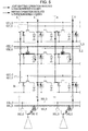
- Fig. 2 is a circuit diagram showing details around unit circuits and data potential generating sections that constitute the electro-optical device in Fig. 1 .
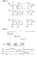
- Fig. 3 is a timing chart for explaining an operation of the electro-optical device in Fig. 1 and Fig. 2 .
- Fig. 4 is an explanatory view (1) visually expressing charging and discharging to/from a capacitative element (C1) in an electro-optical device that operates based on Fig. 3 .
- Fig. 5 an explanatory view (2) visually expressing charging and discharging to/from the capacitative element (C1) in an electro-optical device that operates based on Fig. 3 .
- Fig. 6 is a view showing a constitution of a comparative example relative to the constitution of the electro-optical device according to the first embodiment.
- Fig. 7 is a timing chart for explaining an operation of the constitution of the comparative example in Fig. 6 .
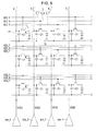
- Fig. 8 is a circuit diagram showing details around unit circuits and data potential generating sections that constitute the electro-optical device according to the second embodiment of the invention.
- Fig. 9 is a timing chart for explaining an operation of the electro-optical device in Fig. 8 .
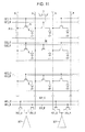
- Fig. 10 is a circuit diagram showing details around unit circuits and data potential generating sections that constitute a modified example (addition of an auxiliary capacitative element) of the electro-optical device according to the first and second embodiments of the invention.
- Fig. 11 is a circuit diagram showing details around unit circuits and data potential generating sections that constitute a modified example (no existence of a capacitative element) of the electro-optical device according to the first and second embodiment of the invention.
- Fig. 12 is a perspective view showing an electronic apparatus to which the electro-optical device according to an aspect of the invention is applied.
- Fig. 13 is a perspective view showing another electronic apparatus to which the electro-optical device according to an aspect of the invention is applied.
- Fig. 14 is a perspective view showing still another electronic apparatus to which the electro-optical device according to an aspect of the invention is applied.
- the electro-optical device 10 is a device that is employed by various electronic apparatus as an apparatus for displaying an image, and has a pixel array section 100, where a plurality of unit circuits P1 are arrayed in a sheet, a scanning line drive circuit 200 and a data line drive circuit 300.
- the scanning line drive circuit 200 and the data line drive circuit 300 are illustrated as individual circuits, but a constitution where a part or all of the circuits are formed in a single circuit is also employed.
- m-pieces of scanning lines 3 extending in the X-direction and n-pieces of data lines 6 (m and n are natural numbers) extending in the Y-direction orthogonal to the X-direction are provided for the pixel array section 100.
- Each unit circuit P1 is arranged at positions corresponding to crossings between the scanning lines 3 and the data lines 6. Therefore, these unit circuits P1 are arrayed in a matrix state of vertical m-rowsxhorizontal n-columns.
- m-pieces of the scanning lines 3 severally include one set of two wirings 3_O and 3_E as shown in Fig. 1 .
- the total number of wirings 3_O and 3_E is 2m-pieces.
- the wiring 3_O is connected to unit circuits P1 positioned on an odd-numbered column
- the wiring 3_E is connected to unit circuits P1 positioned on an even-numbered column.
- the scanning line drive circuit 200 shown in Fig. 1 is a circuit for selecting a plurality of unit circuits P1.
- the scanning line drive circuit 200 creates scan signals G[1]_O to G[m]_E which sequentially become active, and outputs the signals to each of 2m pieces of the wiring 3_O and 3_E which constitute the above-mentioned scanning lines 3.
- transition of the scan signal G[i] supplied to the scanning line 3 of an i-th row means selection of (n/2)-pieces of the unit circuits P1 that belong to the i-th row and odd-numbered column
- transition of the scan signal G[i]_E to an active state means selection of (n/2)-pieces of the unit circuits P1 that belong to the i-th row and even-numbered column.
- the data line drive circuit 300 shown in Fig. 1 creates data potentials VD[1] to VD[n] in response to the gradation data of each of (n/2) pieces of the unit circuits P1 corresponding to the wirings 3_O or 3_E which are selected by the scanning line drive circuit 200, and outputs the potentials to each data line 6. Meanwhile, in the following, data potentials VD output to the data line 6 on the j-th column (j is an integer satisfying 1 ⁇ j ⁇ n) may be indicated as VD[j].
- each scanning line 3 includes two wirings 3_O and 3_E as mentioned above, each of the data potentials VD[1] to VD[n] is also supplied in response to selection or non-selection of the two wirings 3_O or 3_E. Specifically, for example, in response to selection of the wiring 3_O that constitutes the scanning line 3 on the first row, data potentials VD[1], VD[3], ..., VD[2k-1], ...(k is an appropriate integer, but 2k-1 ⁇ n) for unit circuits P1 that are positioned on odd-numbered columns are output to each data line 6.
- the data line drive circuit 300 includes data potential generating sections 301 supporting every 2 columns of the unit circuits P1, first and second switching transistors 302_O and 302_E, and wirings for controlling switching transistors (hereinafter, abbreviated as "wiring for SW") 303_O and 303_E which supply a control signal to each gate of the transistors.
- wiring for SW switching transistors
- the data potential generating sections 301 are provided such that one section supports every two data lines 6. Each of the data potential generating sections 301 generates a data potential in response to on which column in the pixel array section 100 two data lines 6 corresponding to the section are positioned. For example, the data potential generating section 301 shown on the far left side in Fig. 2 generates data potential VD[1] and VD[2].
- control signals SEL_O and SEL_E are output to the wiring for SW 303_O and 303_E respectively.
- the control signals SEL_O and SEL_E transit between the active state and non-active state similarly while appropriately synchronizing with transition of the scan signals G[1]_O to G[m]_E between each active state and non-active state.
- Each of the first and second switching transistors 302_O and 302_E is an N-channel type, and enters the electrically conducting state when the control signals SEL_O and SEL_E enter the active state. Then, in response to the transition of each transistor (302_O, 302_E) between the electrically conducting and non-conducting states, a data potential VD[j-1] is output to the data line 6 of the (j-1)th column in some cases, and a data potential VD[j] is output to the data line 6 of the (j)th column in other cases.
- Fig. 2 is a circuit diagram showing a detail of an electrical constitution regarding each unit circuit P1.
- Each unit circuit P1 as shown in Fig. 2 , has an electric optical element 8, a capacitative element C1 and a transistor Tr.
- the electric optical element 8 is an OLED (Organic Light Emitting Diode) element where a light-emitting layer of an organic EL material is interposed between an anode and a cathode, as shown in Fig. 2 .
- the optical element 8 is arranged between the transistor Tr and a constant potential line (grounding wire) to which constant potential is supplied.
- the anode is an individual electrode that is provided by each unit circuit P1 and controlled by each unit circuit P1
- the cathode is a common electrode that is commonly provided for the unit circuit P1.
- the cathode is connected to a constant potential line to which constant potential is supplied.
- the anode may be a common electrode and the cathode may be an individual electrode.
- the capacitative element C1 is an element for holding the data potential VD[j] supplied from the data line 6. As shown in Fig. 2 , the capacitative element C1 has a first electrode E1 connected to a capacitance line 30 and a second electrode E2 connected to the data line 6.
- grounding potential is supplied to a constant potential line.
- a negative potential is supplied to the constant potential line
- data potential VD[n] showing the highest brightness, out of the data potential VD[j] may be a positive potential
- the data potential VD[1] showing the lowest brightness, out of the data potential VD[j] may be a negative potential.
- grounding potential may exist between the data potential VD[n] and the data potential VD[1].
- the transistor Tr is an N-channel type, and is a switching element that electrically connects a second electrode E2 of the capacitative element C1 with the electric optical element 8 by being electrically conductive when a scanning line 3 is selected. As shown in Fig. 2 , the source of the transistor Tr is connected to the anode of the electric optical element 8, and its drain is connected to the second electrode E2 of the capacitative element C1.
- the gate of the transistor Tr is connected to the scanning line 3.
- the first embodiment has the following characteristics. Specifically, as shown in Fig. 2 , the gate of the transistor Tr included in a unit circuit P1 positioned on an odd-numbered column is connected to a wiring 3_O that constitutes the scanning line 3. On the other hand, the gate of the transistor Tr included in a unit circuit P1 positioned on an even-numbered column is connected to a wiring 3_E that constitutes the scanning line 3.
- the electro-optical device 10 has basic operations i and ii below. i. Writing operation
- This writing operation is an operation to allow a capacitative element C1 in a unit circuit P1 that belongs to a column including an electric optical element 8, which is included in each unit circuit P1 corresponding to a wiring 3_O or 3_E, to hold the data potential VD[j] corresponding to the light emission gradation of the electric optical element 8.
- the data potential VD[3] of an electro-optical device 8 that corresponds to the wiring 3_E included in the scanning line 3 of the second row and positioned on the third column (refer to Fig. 1 ) will be held by a plurality of the capacitative elements C1 in each unit circuit P1 positioned on the third column.
- This light-emitting operation is an operation to allow the electric optical element 8 to perform light emission based on the data potential VD[j] held by the capacitative elements C1 in i.
- This operation includes supplying an active scan signal G[i]_O or G[i]_E to the wiring 3_O or 3_E corresponding to the unit circuit P1 including the electric optical element 8 and making the transistor Tr in the unit circuit P1 enter the electrically conducting state.
- the electric optical element 8 is supplied with a current in response to charge accumulated in the capacitative elements C1, and emits light.
- the electro-optical device 10 of the first embodiment is basically operated based on an appropriate combination of the above-described i and ii, and more details on these points are as follows.
- supplying an active-state control signal SEL_O to a wiring for SW 303_O in the data line drive circuit 300 and supplying a non-active-state control signal SEL_E to a wiring for SW 303_E allow a first switching transistor 302_O to enter the On state and a second switching transistor 302_E to enter the Off state.
- a data potential generating section 301 creates data potentials VD[1], VD[3], ..., VD[2k-1], ..., and supplies this to each data line 6 positioned on a corresponding odd-numbered column.
- the data potential VD[2k-1] corresponds to the electric optical element 8 in each unit circuit P1 positioned on the first row and the odd-numbered column (in Fig. 3 , refer to a note "Corresponding to G[1]_O").
- the i. writing operation for the electric optical element 8 in each unit circuit P1 that is positioned on the first row and the odd-numbered column is ended. Therefore, in this writing period Pw, only half the capacitative element C1 of all the capacitative elements C1 in the pixel array section 100 are involved in charging, and a plurality of the capacitative elements C1 that severally belong to each of the first column, third column,..., (2k-1)th column,... accumulate charge in response to the data potentials VD[1], VD[3],..., VD[2k-1],....
- the scanning line drive circuit 200 supplies an active-state scan signal G[1]_O to the wiring 3_O included in the scanning line 3 on the first row.
- the electric optical element 8 corresponding to the wiring 3_O simultaneously emits light (the ii. light-emitting operation).
- a current that flows in the electric optical element 8 corresponds to a charge amount accumulated in the above-mentioned plurality of the capacitative elements C1.
- Fig. 4 and Fig. 5 visually express the operations above. Specifically, in Fig. 4 , a case is depicted where the control signal SEL_O becomes active, the first switching transistor 302_O enters an electrically conducting state, a plurality of the capacitative elements C1 on the (2k-1)th column, more specifically, the elements that belong to each of the odd-numbered column accumulate charge in response to the data potential VD[2k-1] (in Fig. 4 , refer to bold and solid line arrows, and hatching portion related to them, or the like).
- a case is depicted where the active-state scan signal G[2]_O is supplied to the wiring 3_O included in the scanning line 3 on the second row to allow transistors Tr that belong to the wiring 3_O to enter the On state, and each of the electric optical elements 8 corresponding to the transistors emits light. Further, in this occasion, a case is also depicted where a current is supplied to the electric optical element 8 in response to charge of a plurality of the capacitative elements C1 that belongs to the above-mentioned each column (in Fig. 5 , refer to bold and solid line arrows, and hatching portion related to them, or the like).
- Fig. 5 a case is also depicted where the writing operation for the electric optical element 8 in a unit circuit P1 positioned on the (2k)th column, more specifically, an even-numbered column is performed in parallel with this (in Fig. 5 , refer to bold and dashed line arrows, and hatching portion related to them, or the like).
- the electric optical element 8 on the second row and the wiring 3_O is a subject to be driven to emit light
- the electric optical element 8 on the second row and the wiring 3_E becomes subject to be driven to emit light (this is not shown).
- the above-described operation is performed repeatedly. Specifically, at any given point, a writing operation for the capacitative element C1 that belongs to an odd-numbered column and a light-emitting operation of the electric optical element 8 that belongs to an even-numbered column are performed. At another point, the electric optical element 8 being a subject of light emission will shift sequentially downward while the opposite operation is performed in Fig. 4 and Fig. 5 (or in Fig. 1 and Fig. 2 ).
- a period 1 V shown in Fig. 3 means one vertical scan period that is a period in which selection of scanning line passes through for all scanning lines 3 (more specifically, all of the wirings 3_O and 3_E).
- the electro-optical device 10 of the first embodiment which has such a constitution and performs operation, gives the following effect.
- each scanning line 3 includes two wirings 3_O and 3_E, and each of the wiring 3_O and 3_E is connected to unit circuits P1 positioned on the odd-numbered column and even-numbered column, so that the number of the capacitative elements C1 involved in simultaneous charging or simultaneous discharging in order to drive one electric optical element 8 is half all the capacitative elements C1, and a risk that extremely large current is instantaneously generated is extremely reduced even in each point of charging and discharging.
- Fig. 6 is the comparative example to the constitution of the first embodiment (refer to Fig. 2 comparatively)
- Fig. 7 is the timing chart regarding the operation of the constitution of the comparative example in Fig. 6 (refer to Fig. 3 comparatively).
- a scanning line 3Conv is provided by one corresponding to each row of the unit circuit P1.
- a scanning line 3 corresponding to each row severally includes the two wirings 3_O and 3_E, whereas only one wiring exists in the comparative example.
- the writing period Pw and the light emission period Pd appear accurately and alternately as shown in Fig. 7 .
- a writing operation for the electric optical element 8 that belongs to the first row which is an operation that comes firstly
- a light-emitting operation for the electric optical element 8 is performed secondly.
- a writing operation for the electric optical element 8 that belongs to second row is performed.
- the scanning line drive circuit 200 creates scan signals G[1]_F to G[m]_T which sequentially become active and outputs them to the 3m-pieces of wirings 3_F, 3_S and 3_T.
- the gate of the transistor Tr included in each unit circuit P1 is connected as follows. Firstly, the gate of the transistor Tr, which is included in a unit circuit P1 positioned on the first column, fourth column, ..., (1 +3z)th column, ..., is connected to the wiring 3_F that constitutes the scanning line 3. Secondly, the gate of the transistor Tr, which is included in a unit circuit P1 positioned on the second column, fifth column, ..., (2+3z)th column, ..., is connected to the wiring 3_S that constitutes the scanning line 3.
- the three types of unit circuits P1 above may be referred to as a unit circuit P1 of a first group, a unit circuit P1 of a second group, and a unit circuit P1 of a third group.
- the data line drive circuit 300 includes a data potential generating section 304 corresponding to each data line 6.
- the data potential generating section 304 mentioned here can be grouped into the data potential generating sections 304_F, 304_S and 304_T (refer to Fig. 8 ) corresponding to all unit circuits P1 that are grouped into the first to third groups of the unit circuits P1 as mentioned above.
- the data potential generating section 304_F solely generates/supplies the data potential VD[1], VD[4],..., VD[1+3z],... for the unit circuit P1 of the first group connected to the wiring 3_F.
- the data potential generating sections 304_S and 304_T solely generate/supply data potential VD[2+3z] and VD[3+3z] for the unit circuits P1 of the second and third groups connected to the wirings 3_S and 3_T, respectively.
- the data potential generating section 304 falls under one specific example of the "data potential generating section" in the invention. Further, this specification uses the reference numeral “304" as a reference numeral that collectively calls the reference numerals "304_F”, "304_S” and "304_T”.
- the electro-optical device operates or acts as follows. Firstly, in the writing period Pw shown on the far left side of Fig. 9 , the data potential generating section 304 _F in the data line drive circuit 300 creates a data potential VD[1+3z], and supplies it to a corresponding data line 6 (i. writing operation above).
- the data potential VD[1+3z] corresponds to the electric optical element 8 in a unit circuit P1 positioned on the first row and a unit circuit P1 of the first group (in Fig. 9 , refer to items "Corresponding to G[1]_F").
- the writing operation for the electric optical element 8 in a unit circuit P1 positioned on the first row and a unit circuit P1 of the second group is also performed in parallel.
- the writing operation starts approximately half way through the writing period Pw for the first group (in Fig. 9 , refer to the items "Corresponding to G[1]_S").
- the essence of the operation in this case is not different from the case of the above-mentioned writing operation for the first row.
- the data potential generating section 304_S in the data line drive circuit 300 creates the data potential VD[2+3z], and supplies it to a corresponding data line 6.
- the data potential VD[1] corresponding to the electric optical element 8 of the first row and first column is held by the capacitative elements C1 in all unit circuits P1 included in the first column.
- the data potential VD[2] corresponding to the electric optical element 8 of the first row and second column is held by the capacitative elements C1 in all unit circuits P1 included in the second column.
- the scanning line drive circuit 200 supplies an active-state scan signal G[1]_F to the wiring 3_F included in the scanning line 3 on the first row.
- electric optical elements 8 that belong to the unit circuit P1 positioned on the first row and the unit circuit P1 of the first group emit light simultaneously (ii. light-emitting operation).
- a current flowing in the electric optical elements 8 corresponds to a charge amount accumulated in the capacitative elements C1 that belong to the above-mentioned first column.
- one unit period 1 T ends (refer to top areas of Fig. 9 ).
- the above-mentioned writing period Pw for the first row and second groups still continues.
- the light-emitting operation for the first group and the writing operation for the second group are performed in parallel.
- the writing operation for the capacitative elements C1 that belong to the unit circuits P1 of the first and second, the second and third, or the first and third groups can be performed in parallel as described the above. Specifically, comparing this operation with the fact that the writing operation for an odd-numbered column and a light-emitting operation for an even-numbered column (or its opposite) can be performed in parallel in the first embodiment, time usage is more efficient in the second embodiment. Actually in Fig. 9 , it turns out that a longer writing period than Fig. 3 can be realized by utilizing this.
- an operational effect better than the operational effect exerted by the first embodiment could be exerted.
- the first and second switching transistors 302_O and 302_E and the wirings for SW 303_O and 303_E, which are installed in the first embodiment, are not necessary. Therefore, according to the second embodiment, cost reduction required for installing these parts is expected. Further, control or the like of the first and second switching transistors 302_O and 302_E through the wirings for SW 303_O and 303_E is also not necessary, so that a simplified operation sequence or the like can be realized as well.
- a subject to be charged in i. writing operation mentioned above is the capacitative element C1 included in the unit circuit P1, but the invention is not limited to such.
- an auxiliary capacitative element Cs may be connected to the data line 6.
- one electrode E3 is connected to the data line 6 and the other electrode E4 is connected to a potential line to which a fixed potential is supplied.
- Fig. 10 illustrates where the capacitative element Cs is added to the constitution of Fig. 2 while using the first embodiment as a premise, it goes without saying that the capacitative element Cs can be added while using Fig. 8 for the second embodiment as a premise.
- the auxiliary capacitative element Cs is also charged in addition to a predetermined capacitative element C1. Further, in the driving period Pd in each unit period 1T shown in each drawing, charge from the auxiliary capacitative element Cs is supplied to a unit circuit P1 corresponding to the auxiliary capacitative element Cs.
- a unit circuit P11 need not include the capacitative elements C1 in each of the embodiments.
- charge in response to the data potential VD[j] is stored in capacitance attached to each data line 6, more specifically, parasitic capacitance that is parasitic between the data line 6 and the anode of the electric optical element 8 or the like, for example.
- one each of the data line 6 is provided for each column of unit circuit P1, but the invention is not limited to such an aspect.
- the data line 6 may also have a plurality of wirings. Then, in this case, for example, an aspect where a unit circuit P1 positioned on an odd-numbered row is connected to one wiring out of the plurality of wirings and a unit circuit P1 positioned on an even-numbered row is connected to another wiring is possible as a variation of a specific mode of the invention.
- a capacitative element C1 being a subject of charging or discharging is a capacitative element C1 that belongs to a unit circuit P1 of the first group and is included in a unit circuit P1 positioned on an odd-numbered row, for example, the above-mentioned effect of preventing the generation of a large current may be achieved better.
- Fig. 12 is a perspective view showing a constitution of a mobile personal computer in which the electro-optical device 10 according to the embodiment is utilized as an image display apparatus.
- a personal computer 2000 is equipped with the electro-optical device 10 as a display device and a main body section 2010.
- a power switch 2001 and a keyboard 2002 are provided for the main body section 2010.
- Fig. 13 shows a cell phone to which the electro-optical device 10 according to the embodiment is applied.
- a cell phone 3000 is equipped with a plurality of operation buttons 3001, a scroll button 3002 and the electro-optical device 10 as a display device. By operating the scroll button 3002, a screen displayed on the electro-optical device 10 is scrolled.
- Fig. 14 shows a personal digital assistant (PDA: Personal Digital Assistant) to which the electro-optical device 10 according to the embodiment is applied.
- a personal digital assistance 4000 is equipped with a plurality of operation buttons 4001, a power switch 4002 and the electro-optical device 10 as a display device.
- the power switch 4002 When the power switch 4002 is operated, various information such as an address book and a schedule book is displayed on the electro-optical device 10.
- a digital still camera As electronic apparatus to which the electro-optical device according to an aspect of the invention is applied, other than the ones shown in Fig. 12 to Fig. 14 , a digital still camera, a television set, a video camera, a car navigation unit, a pager, an electronic notebook, an electronic paper, a calculator, a word processor, a workstation, a videophone, a POS terminal, a video player, a device equipped with a touch panel or the like are cited.
Landscapes
- Engineering & Computer Science (AREA)
- Physics & Mathematics (AREA)
- Computer Hardware Design (AREA)
- General Physics & Mathematics (AREA)
- Theoretical Computer Science (AREA)
- Control Of Indicators Other Than Cathode Ray Tubes (AREA)
- Control Of El Displays (AREA)
- Electroluminescent Light Sources (AREA)
Applications Claiming Priority (1)
| Application Number | Priority Date | Filing Date | Title |
|---|---|---|---|
| JP2009089618A JP5439913B2 (ja) | 2009-04-01 | 2009-04-01 | 電気光学装置及びその駆動方法、並びに電子機器 |
Publications (2)
| Publication Number | Publication Date |
|---|---|
| EP2237255A2 true EP2237255A2 (de) | 2010-10-06 |
| EP2237255A3 EP2237255A3 (de) | 2011-03-23 |
Family
ID=42307942
Family Applications (1)
| Application Number | Title | Priority Date | Filing Date |
|---|---|---|---|
| EP10158539A Withdrawn EP2237255A3 (de) | 2009-04-01 | 2010-03-30 | Elektrooptische Vorrichtung und Verfahren zur Ansteuerung, sowie elektronische Vorrichtung |
Country Status (6)
| Country | Link |
|---|---|
| US (1) | US8686930B2 (de) |
| EP (1) | EP2237255A3 (de) |
| JP (1) | JP5439913B2 (de) |
| KR (1) | KR101636452B1 (de) |
| CN (1) | CN101859534A (de) |
| TW (1) | TWI497467B (de) |
Cited By (1)
| Publication number | Priority date | Publication date | Assignee | Title |
|---|---|---|---|---|
| EP2506589A3 (de) * | 2011-03-29 | 2012-11-28 | Samsung Display Co., Ltd. | Anzeigevorrichtung und Verfahren zu ihrer Ansteuerung |
Families Citing this family (4)
| Publication number | Priority date | Publication date | Assignee | Title |
|---|---|---|---|---|
| JP5797134B2 (ja) * | 2012-03-13 | 2015-10-21 | シャープ株式会社 | 表示装置およびその駆動方法 |
| JP6427863B2 (ja) * | 2013-10-31 | 2018-11-28 | セイコーエプソン株式会社 | 電気光学装置、電気光学装置の駆動方法及び電子機器 |
| JP6572738B2 (ja) * | 2015-10-30 | 2019-09-11 | セイコーエプソン株式会社 | 電気光学装置、電子機器、及び電気光学装置の駆動方法 |
| US10861381B1 (en) * | 2019-06-06 | 2020-12-08 | Mikro Mesa Technology Co., Ltd. | Micro light-emitting diode display having two or more types of data lines |
Citations (2)
| Publication number | Priority date | Publication date | Assignee | Title |
|---|---|---|---|---|
| JP2000122608A (ja) | 1998-10-13 | 2000-04-28 | Seiko Epson Corp | 表示装置及び電子機器 |
| US20090195534A1 (en) | 2008-02-06 | 2009-08-06 | Seiko Epson Corporation | Electro-optical device, method of driving electro-optical device, and electronic apparatus |
Family Cites Families (20)
| Publication number | Priority date | Publication date | Assignee | Title |
|---|---|---|---|---|
| GB2081018B (en) * | 1980-07-31 | 1985-06-26 | Suwa Seikosha Kk | Active matrix assembly for display device |
| JP2689917B2 (ja) * | 1994-08-10 | 1997-12-10 | 日本電気株式会社 | アクティブマトリクス型電流制御型発光素子の駆動回路 |
| JP2689916B2 (ja) | 1994-08-09 | 1997-12-10 | 日本電気株式会社 | アクティブマトリクス型電流制御型発光素子の駆動回路 |
| US5714968A (en) * | 1994-08-09 | 1998-02-03 | Nec Corporation | Current-dependent light-emitting element drive circuit for use in active matrix display device |
| JP3471928B2 (ja) * | 1994-10-07 | 2003-12-02 | 株式会社半導体エネルギー研究所 | アクティブマトリクス表示装置の駆動方法 |
| JP4406951B2 (ja) * | 1999-03-25 | 2010-02-03 | Tdk株式会社 | 薄膜発光素子の駆動方法および駆動回路 |
| JP3778079B2 (ja) * | 2001-12-20 | 2006-05-24 | 株式会社日立製作所 | 表示装置 |
| JP2004012872A (ja) * | 2002-06-07 | 2004-01-15 | Nec Electronics Corp | 表示装置及びその駆動方法 |
| US6911964B2 (en) * | 2002-11-07 | 2005-06-28 | Duke University | Frame buffer pixel circuit for liquid crystal display |
| JP5105699B2 (ja) * | 2004-06-18 | 2012-12-26 | 三菱電機株式会社 | 表示装置 |
| KR100688800B1 (ko) * | 2004-11-17 | 2007-03-02 | 삼성에스디아이 주식회사 | 발광 표시장치와 그의 구동방법 |
| JP2006259530A (ja) * | 2005-03-18 | 2006-09-28 | Seiko Epson Corp | 有機el装置及びその駆動方法並びに電子機器 |
| WO2006103802A1 (ja) * | 2005-03-25 | 2006-10-05 | Sharp Kabushiki Kaisha | 表示装置及びその駆動方法 |
| US8619007B2 (en) * | 2005-03-31 | 2013-12-31 | Lg Display Co., Ltd. | Electro-luminescence display device for implementing compact panel and driving method thereof |
| KR100761077B1 (ko) * | 2005-05-12 | 2007-09-21 | 삼성에스디아이 주식회사 | 유기 전계발광 표시장치 |
| WO2007040088A1 (ja) * | 2005-09-30 | 2007-04-12 | Kyocera Corporation | 画像表示装置およびその駆動方法 |
| KR100776488B1 (ko) * | 2006-02-09 | 2007-11-16 | 삼성에스디아이 주식회사 | 데이터 구동회로 및 이를 구비한 평판 표시장치 |
| US8471806B2 (en) * | 2006-05-24 | 2013-06-25 | Sharp Kabushiki Kaisha | Display panel drive circuit and display |
| KR101352175B1 (ko) * | 2007-05-09 | 2014-01-16 | 엘지디스플레이 주식회사 | 유기발광다이오드 표시장치와 그 구동방법 |
| JP2010060648A (ja) * | 2008-09-01 | 2010-03-18 | Hitachi Displays Ltd | 画像表示装置 |
-
2009
- 2009-04-01 JP JP2009089618A patent/JP5439913B2/ja not_active Expired - Fee Related
-
2010
- 2010-03-26 KR KR1020100027222A patent/KR101636452B1/ko not_active Expired - Fee Related
- 2010-03-29 TW TW099109449A patent/TWI497467B/zh not_active IP Right Cessation
- 2010-03-30 EP EP10158539A patent/EP2237255A3/de not_active Withdrawn
- 2010-04-01 US US12/752,538 patent/US8686930B2/en active Active
- 2010-04-01 CN CN201010159904A patent/CN101859534A/zh active Pending
Patent Citations (2)
| Publication number | Priority date | Publication date | Assignee | Title |
|---|---|---|---|---|
| JP2000122608A (ja) | 1998-10-13 | 2000-04-28 | Seiko Epson Corp | 表示装置及び電子機器 |
| US20090195534A1 (en) | 2008-02-06 | 2009-08-06 | Seiko Epson Corporation | Electro-optical device, method of driving electro-optical device, and electronic apparatus |
Cited By (2)
| Publication number | Priority date | Publication date | Assignee | Title |
|---|---|---|---|---|
| EP2506589A3 (de) * | 2011-03-29 | 2012-11-28 | Samsung Display Co., Ltd. | Anzeigevorrichtung und Verfahren zu ihrer Ansteuerung |
| US9584799B2 (en) | 2011-03-29 | 2017-02-28 | Samsung Display Co., Ltd. | Display device and driving method thereof |
Also Published As
| Publication number | Publication date |
|---|---|
| TW201108178A (en) | 2011-03-01 |
| TWI497467B (zh) | 2015-08-21 |
| KR20100109849A (ko) | 2010-10-11 |
| US20100253713A1 (en) | 2010-10-07 |
| JP5439913B2 (ja) | 2014-03-12 |
| JP2010243611A (ja) | 2010-10-28 |
| EP2237255A3 (de) | 2011-03-23 |
| KR101636452B1 (ko) | 2016-07-05 |
| US8686930B2 (en) | 2014-04-01 |
| CN101859534A (zh) | 2010-10-13 |
Similar Documents
| Publication | Publication Date | Title |
|---|---|---|
| US11626065B2 (en) | Display substrate, driving method thereof and display device | |
| US8502752B2 (en) | Electro-optical apparatus, having a plurality of wirings forming a data line driving method thereof, and electronic device | |
| US9280930B2 (en) | Back to back pre-charge scheme | |
| JP4655800B2 (ja) | 電気光学装置および電子機器 | |
| US8610644B2 (en) | Electro-optical device, method of driving electro-optical device, and electronic apparatus | |
| US11574571B2 (en) | Display device having switching signal line between display regions | |
| US9053669B2 (en) | Apparatus for scan driving including scan driving units | |
| EP2209107A1 (de) | Datentreiber und damit versehene organische lichtemittierende Anzeigenvorrichtung | |
| US8686930B2 (en) | Electro-optical device having odd and even scanning lines for alternately driving odd and even column pixels and method for driving the same | |
| US7652645B2 (en) | Light emitting display | |
| JP2006011095A (ja) | 表示パネル用ドライバ手段および画像表示装置 | |
| EP1865604A1 (de) | Treiberschaltung und organische Elektrolumineszenzanzeige dafür | |
| JP2006113162A (ja) | 電気光学装置、これを駆動する回路および方法、ならびに電子機器 | |
| JP2010249920A (ja) | 電気光学装置及びその駆動方法並びに電子機器 | |
| EP1820180B1 (de) | Anzeigeeinrichtung und elektronische vorrichtung damit | |
| US8427401B2 (en) | Electro-optical device and method for driving the same by applying a capacitance charge, and electronic apparatus | |
| JP4753096B2 (ja) | 表示駆動装置、表示装置及びその表示駆動方法 | |
| US20100259571A1 (en) | Electro-optical apparatus, driving method thereof and electronic device | |
| JP2006235162A (ja) | 電気光学装置、電気光学装置の駆動回路およびその駆動方法 | |
| JP2012098441A (ja) | 電気光学装置、その駆動方法、および電子機器 | |
| CN118675456A (zh) | 驱动电路、驱动方法和显示装置 | |
| JP2010266784A (ja) | 発光装置および電子機器 | |
| JP2011043537A (ja) | 画素回路、電気光学装置及び電子機器 | |
| JP2006243222A (ja) | 駆動回路、それを用いた電気光学装置、電子機器、および、電気光学装置の駆動方法 | |
| JP2011095644A (ja) | 発光装置及びその駆動方法並びに電子機器 |
Legal Events
| Date | Code | Title | Description |
|---|---|---|---|
| PUAI | Public reference made under article 153(3) epc to a published international application that has entered the european phase |
Free format text: ORIGINAL CODE: 0009012 |
|
| AK | Designated contracting states |
Kind code of ref document: A2 Designated state(s): AT BE BG CH CY CZ DE DK EE ES FI FR GB GR HR HU IE IS IT LI LT LU LV MC MK MT NL NO PL PT RO SE SI SK SM TR |
|
| AX | Request for extension of the european patent |
Extension state: AL BA ME RS |
|
| PUAL | Search report despatched |
Free format text: ORIGINAL CODE: 0009013 |
|
| AK | Designated contracting states |
Kind code of ref document: A3 Designated state(s): AT BE BG CH CY CZ DE DK EE ES FI FR GB GR HR HU IE IS IT LI LT LU LV MC MK MT NL NO PL PT RO SE SI SK SM TR |
|
| AX | Request for extension of the european patent |
Extension state: AL BA ME RS |
|
| STAA | Information on the status of an ep patent application or granted ep patent |
Free format text: STATUS: THE APPLICATION IS DEEMED TO BE WITHDRAWN |
|
| 18D | Application deemed to be withdrawn |
Effective date: 20110926 |