EP2237324A1 - Panneau solaire et son procédé de fabrication - Google Patents
Panneau solaire et son procédé de fabrication Download PDFInfo
- Publication number
- EP2237324A1 EP2237324A1 EP08871605A EP08871605A EP2237324A1 EP 2237324 A1 EP2237324 A1 EP 2237324A1 EP 08871605 A EP08871605 A EP 08871605A EP 08871605 A EP08871605 A EP 08871605A EP 2237324 A1 EP2237324 A1 EP 2237324A1
- Authority
- EP
- European Patent Office
- Prior art keywords
- solar cell
- cell panel
- frame
- panel body
- substrate
- Prior art date
- Legal status (The legal status is an assumption and is not a legal conclusion. Google has not performed a legal analysis and makes no representation as to the accuracy of the status listed.)
- Withdrawn
Links
- 238000004519 manufacturing process Methods 0.000 title claims description 33
- 238000000034 method Methods 0.000 title abstract description 24
- 239000000758 substrate Substances 0.000 claims abstract description 69
- 238000006243 chemical reaction Methods 0.000 claims abstract description 16
- 239000000853 adhesive Substances 0.000 claims description 32
- 230000001070 adhesive effect Effects 0.000 claims description 31
- 238000007789 sealing Methods 0.000 claims description 29
- 239000003795 chemical substances by application Substances 0.000 claims description 17
- 229920001296 polysiloxane Polymers 0.000 claims description 10
- 229920002635 polyurethane Polymers 0.000 claims description 9
- 239000004814 polyurethane Substances 0.000 claims description 9
- 229920000642 polymer Polymers 0.000 claims description 8
- 125000003808 silyl group Chemical group [H][Si]([H])([H])[*] 0.000 claims description 8
- 239000010410 layer Substances 0.000 description 43
- 229910052782 aluminium Inorganic materials 0.000 description 15
- XAGFODPZIPBFFR-UHFFFAOYSA-N aluminium Chemical compound [Al] XAGFODPZIPBFFR-UHFFFAOYSA-N 0.000 description 15
- 239000011521 glass Substances 0.000 description 11
- 239000010409 thin film Substances 0.000 description 9
- XLYOFNOQVPJJNP-UHFFFAOYSA-N water Substances O XLYOFNOQVPJJNP-UHFFFAOYSA-N 0.000 description 8
- 238000005516 engineering process Methods 0.000 description 7
- 239000010408 film Substances 0.000 description 7
- 238000005304 joining Methods 0.000 description 7
- 239000000463 material Substances 0.000 description 7
- 238000010248 power generation Methods 0.000 description 7
- 229920000139 polyethylene terephthalate Polymers 0.000 description 5
- 239000005020 polyethylene terephthalate Substances 0.000 description 5
- 238000004078 waterproofing Methods 0.000 description 5
- 230000006866 deterioration Effects 0.000 description 4
- 229910052751 metal Inorganic materials 0.000 description 4
- 239000002184 metal Substances 0.000 description 4
- 230000000694 effects Effects 0.000 description 3
- 230000008595 infiltration Effects 0.000 description 3
- 238000001764 infiltration Methods 0.000 description 3
- 230000007774 longterm Effects 0.000 description 3
- 238000003825 pressing Methods 0.000 description 3
- 229910000577 Silicon-germanium Inorganic materials 0.000 description 2
- LEVVHYCKPQWKOP-UHFFFAOYSA-N [Si].[Ge] Chemical compound [Si].[Ge] LEVVHYCKPQWKOP-UHFFFAOYSA-N 0.000 description 2
- 230000002411 adverse Effects 0.000 description 2
- 229910021417 amorphous silicon Inorganic materials 0.000 description 2
- DQXBYHZEEUGOBF-UHFFFAOYSA-N but-3-enoic acid;ethene Chemical compound C=C.OC(=O)CC=C DQXBYHZEEUGOBF-UHFFFAOYSA-N 0.000 description 2
- 229910021419 crystalline silicon Inorganic materials 0.000 description 2
- 238000001035 drying Methods 0.000 description 2
- 239000000428 dust Substances 0.000 description 2
- 239000005038 ethylene vinyl acetate Substances 0.000 description 2
- 239000000945 filler Substances 0.000 description 2
- 239000011888 foil Substances 0.000 description 2
- 238000010438 heat treatment Methods 0.000 description 2
- 229920001200 poly(ethylene-vinyl acetate) Polymers 0.000 description 2
- 238000012797 qualification Methods 0.000 description 2
- 230000002787 reinforcement Effects 0.000 description 2
- 229920005989 resin Polymers 0.000 description 2
- 239000011347 resin Substances 0.000 description 2
- 229920003002 synthetic resin Polymers 0.000 description 2
- 239000000057 synthetic resin Substances 0.000 description 2
- 230000003139 buffering effect Effects 0.000 description 1
- 239000006227 byproduct Substances 0.000 description 1
- 239000013078 crystal Substances 0.000 description 1
- 230000007547 defect Effects 0.000 description 1
- 238000000151 deposition Methods 0.000 description 1
- 238000010030 laminating Methods 0.000 description 1
- 230000014759 maintenance of location Effects 0.000 description 1
- 229910021424 microcrystalline silicon Inorganic materials 0.000 description 1
- 239000000203 mixture Substances 0.000 description 1
- -1 poly ethylene terephthalate Polymers 0.000 description 1
- 239000002994 raw material Substances 0.000 description 1
- 239000002990 reinforced plastic Substances 0.000 description 1
- 230000000717 retained effect Effects 0.000 description 1
- 239000000565 sealant Substances 0.000 description 1
- 239000004065 semiconductor Substances 0.000 description 1
- 239000002356 single layer Substances 0.000 description 1
Images


Classifications
-
- H—ELECTRICITY
- H10—SEMICONDUCTOR DEVICES; ELECTRIC SOLID-STATE DEVICES NOT OTHERWISE PROVIDED FOR
- H10F—INORGANIC SEMICONDUCTOR DEVICES SENSITIVE TO INFRARED RADIATION, LIGHT, ELECTROMAGNETIC RADIATION OF SHORTER WAVELENGTH OR CORPUSCULAR RADIATION
- H10F71/00—Manufacture or treatment of devices covered by this subclass
-
- H—ELECTRICITY
- H02—GENERATION; CONVERSION OR DISTRIBUTION OF ELECTRIC POWER
- H02S—GENERATION OF ELECTRIC POWER BY CONVERSION OF INFRARED RADIATION, VISIBLE LIGHT OR ULTRAVIOLET LIGHT, e.g. USING PHOTOVOLTAIC [PV] MODULES
- H02S20/00—Supporting structures for PV modules
-
- H—ELECTRICITY
- H02—GENERATION; CONVERSION OR DISTRIBUTION OF ELECTRIC POWER
- H02S—GENERATION OF ELECTRIC POWER BY CONVERSION OF INFRARED RADIATION, VISIBLE LIGHT OR ULTRAVIOLET LIGHT, e.g. USING PHOTOVOLTAIC [PV] MODULES
- H02S30/00—Structural details of PV modules other than those related to light conversion
- H02S30/10—Frame structures
-
- F—MECHANICAL ENGINEERING; LIGHTING; HEATING; WEAPONS; BLASTING
- F24—HEATING; RANGES; VENTILATING
- F24S—SOLAR HEAT COLLECTORS; SOLAR HEAT SYSTEMS
- F24S25/00—Arrangement of stationary mountings or supports for solar heat collector modules
- F24S25/60—Fixation means, e.g. fasteners, specially adapted for supporting solar heat collector modules
- F24S2025/601—Fixation means, e.g. fasteners, specially adapted for supporting solar heat collector modules by bonding, e.g. by using adhesives
-
- F—MECHANICAL ENGINEERING; LIGHTING; HEATING; WEAPONS; BLASTING
- F24—HEATING; RANGES; VENTILATING
- F24S—SOLAR HEAT COLLECTORS; SOLAR HEAT SYSTEMS
- F24S80/00—Details, accessories or component parts of solar heat collectors not provided for in groups F24S10/00-F24S70/00
- F24S80/40—Casings
-
- F—MECHANICAL ENGINEERING; LIGHTING; HEATING; WEAPONS; BLASTING
- F24—HEATING; RANGES; VENTILATING
- F24S—SOLAR HEAT COLLECTORS; SOLAR HEAT SYSTEMS
- F24S80/00—Details, accessories or component parts of solar heat collectors not provided for in groups F24S10/00-F24S70/00
- F24S80/70—Sealing means
-
- Y—GENERAL TAGGING OF NEW TECHNOLOGICAL DEVELOPMENTS; GENERAL TAGGING OF CROSS-SECTIONAL TECHNOLOGIES SPANNING OVER SEVERAL SECTIONS OF THE IPC; TECHNICAL SUBJECTS COVERED BY FORMER USPC CROSS-REFERENCE ART COLLECTIONS [XRACs] AND DIGESTS
- Y02—TECHNOLOGIES OR APPLICATIONS FOR MITIGATION OR ADAPTATION AGAINST CLIMATE CHANGE
- Y02E—REDUCTION OF GREENHOUSE GAS [GHG] EMISSIONS, RELATED TO ENERGY GENERATION, TRANSMISSION OR DISTRIBUTION
- Y02E10/00—Energy generation through renewable energy sources
- Y02E10/50—Photovoltaic [PV] energy
-
- Y—GENERAL TAGGING OF NEW TECHNOLOGICAL DEVELOPMENTS; GENERAL TAGGING OF CROSS-SECTIONAL TECHNOLOGIES SPANNING OVER SEVERAL SECTIONS OF THE IPC; TECHNICAL SUBJECTS COVERED BY FORMER USPC CROSS-REFERENCE ART COLLECTIONS [XRACs] AND DIGESTS
- Y10—TECHNICAL SUBJECTS COVERED BY FORMER USPC
- Y10T—TECHNICAL SUBJECTS COVERED BY FORMER US CLASSIFICATION
- Y10T156/00—Adhesive bonding and miscellaneous chemical manufacture
- Y10T156/10—Methods of surface bonding and/or assembly therefor
Definitions
- the present invention relates to solar cells.
- solar cells include thin-film solar cells where photoelectric conversion elements are disposed directly on, for example, a glass substrate and crystalline solar cells where photoelectric conversion elements are disposed on a crystal substrate.
- the surface having the photoelectric conversion elements is covered with a filler or a sealing agent to form a solar cell panel body.
- crystalline solar cells for example, crystalline photoelectric conversion elements are bonded to the substrate, and the substrate is covered with a filler or a sealing agent to form a solar cell panel body.
- Such solar cell panel bodies are fixed to metal frames, such as aluminum frames, to form panel structures.
- FIG. 1 is a partial cross-sectional view showing an exemplary structure of a conventional solar cell panel.
- the solar cell panel includes a solar cell panel body 103, a frame 102, and a gasket 104.
- the solar cell panel body 103 includes a thin-film solar cell module or a crystalline solar cell module.
- the frame 102 is a metal frame, such as an aluminum frame.
- the frame 102 includes a module holder 102-1 for holding the solar cell panel body 103 via the gasket 104, a shape keeper 102-3 for maintaining the shape of the frame 102, and a joint 102-2 for joining the module holder 102-1 and the shape keeper 102-3.
- the solar cell panel body 103 is fitted to the module holder 102-1 having an approximately angular-U shaped cross-section for holding the plate-like solar cell panel body 103 with the frame 102.
- the gasket 104 is used as a buffer for buffering thermal and mechanical stresses between the glass substrate of the solar cell panel body 103 and aluminum of the frame 102.
- the fin-shaped shape keeper 102-3 is disposed on the bottom to reduce widening of the frame 102 due to insufficient strength of the aluminum.
- Patent Document 1 discloses a supporting frame structure for a solar cell panel.
- an outer frame serving as a reinforcement member is fitted to the periphery of a solar cell panel that is formed by vapor-depositing a semiconductor film serving as a power-generating area on a glass panel serving as a substrate, and a deformation-preventing member made of a transparent bar-shaped member, such as reinforced glass or reinforced plastic, is bonded to at least a surface of the solar cell panel.
- the frame employed here has an approximately angular-U shaped cross-section.
- Patent Document 2 discloses a solar housing.
- This solar housing is produced by sealing a plurality of solar cell elements with a sealing agent.
- the periphery of a solar photovoltaic power generation module having a transparent substrate provided with the sealed solar cell elements is fitted into a frame.
- the periphery is fixed with the sealing agent, and portions where the terminals of the elements and the terminals of external devices are connected are sealed with a sealing agent in a terminal box.
- the elements are sealed with a cured room-temperature-curing organopolysiloxane composition, in which deep-section curing is brought about by producing water internally as a by-product.
- the frame employed here has an approximately angular-U shaped cross-section.
- Patent Document 3 discloses a method of producing a solar cell module.
- a frame member is fixed to the periphery of a solar cell panel which is formed by laminating surface glass, solar cells, and a back sheet to form an integrated structure.
- the surface glass, the solar cells, and the back sheet are temporarily fixed with an adhesive; a high-temperature-curing waterproofing agent is applied to the periphery of this temporarily fixed solar cell panel; the periphery of the solar cell panel is fitted into the channel of a frame having an approximately angular-U shaped cross-section; and the solar cell panel and the frame member at the periphery of the solar cell panel are heated to cure the adhesive agent and the waterproofing agent simultaneously.
- the frame employed here has an approximately angular-U shaped cross-section.
- Patent Document 4 discloses a frameless solar cell module.
- a first translucent substrate has a surface provided with a thin-film solar cell layer and an insulating layer covering the whole surface of the thin-film solar cell layer; and the surface of the insulating layer is bonded to a second translucent substrate at least having the same size as that of the first substrate, with a synthetic resin layer therebetween.
- Patent Document 1 Japanese Unexamined Patent Application, Publication No. 2004-87884
- Patent Document 2 Japanese Unexamined Patent Application, Publication No. 2000-349322
- Patent Document 3 Japanese Unexamined Patent Application, Publication No. 2005-19507
- Patent Document 4 Japanese Unexamined Patent Application, Publication No. HEI 09-331079
- the solar cell panel disclosed in Patent Document 1 although the solar cell panel is reinforced with a reinforcement member, the solar cell panel body is fitted into a frame having an approximately angular-U shaped cross-section. Accordingly, there is a possibility of problems such that moisture may remain in the "angular-U" portion of the approximately angular-U shaped cross-section; use of a gasket etc. may be necessary; the back sheet may be involved in the holding; and undulation or distortion of the solar cell panel body may have some influence.
- the solar cell panel body is fitted into a frame having an approximately angular-U shaped cross-section. Accordingly, there is a possibility of problems such that moisture may remain in the "angular-U" portion; and undulation or distortion of the solar cell panel body may have some influence.
- the solar cell panel disclosed in Patent Document 4 employs a synthetic resin layer surrounding the periphery of the solar cell panel body instead of the frame, it has a frameless structure. That is, none of the frames of the solar cell panels described in Patent Documents 1 to 4 have an approximately L-shaped cross-section.
- a buffer such as the gasket 104, for relieving the thermal and mechanical stresses is essential, resulting in increases in the numbers of raw materials and processes.
- the gasket 104 does not fix the glass substrate to the aluminum frame, a fin-shaped shape keeper 102-3 is necessary for reducing widening of the frame 102.
- the buffer is a sealant or the like, it is difficult to uniformly apply the buffer to the entire interface between the glass substrate and the aluminum frame. Accordingly, a large amount of surplus buffer that sticks out must be removed.
- the present invention has been made under such circumstances, and an object of the present invention is to provide a solar cell panel that hardly retains any moisture and that has high reliability, and a method of fabricating the solar cell panel.
- Another object of the present invention is to provide a solar cell panel that can be attached to a frame by an automated process and a method of fabricating the solar cell panel.
- Another object of the present invention is to provide a solar cell panel that can be easily fabricated with a reduced number of processes at lower cost and a method of fabricating the solar cell panel.
- the solar cell panel of the present invention includes a solar cell panel body, a frame, and a joint.
- the solar cell panel body includes a substrate having photoelectric conversion elements mounted on a first surface.
- the frame has an approximately L-shaped cross-section.
- the joint connects the frame and a second surface, opposite to the first surface, of the substrate.
- the frame has an approximately L-shaped cross-section, not the approximately angular-U shaped cross-section. Therefore, the frame does not have a portion between the solar cell panel body and the frame where moisture remains, such as the "angular-U" portion of the approximately angular-U shaped cross-section.
- the influence of moisture on the solar cell panel body is significantly reduced, which increases the weatherability and the long-term reliability of the solar cell panel.
- a member such as a gasket, which is used in the frame having an approximately angular-U shaped cross-section, is unnecessary, which reduces the cost.
- the second surface of the substrate of the solar cell panel body is bonded to the frame, and the frame holds the solar cell panel body at the bonding portion. That is, the first surface of the substrate, including photoelectric conversion elements, is not involved in the holding of the solar cell panel body.
- the holding (adhesion) reliability is improved. Furthermore, since the structure in which the substrate of the solar cell panel body and the frame are bonded is simple, unlike the case of the frame having an approximately angular-U shaped cross-section, it is unnecessary to fit the solar cell panel body into the frame.
- the joint absorbs the influences of undulation, distortion, and stress-deformation of the solar cell panel body; and has a structure that allows extremely simple fabrication.
- the frame preferably includes a frame member and an overhang member.
- the frame member here surrounds the outer edge of the solar cell panel body in a frame shape.
- the overhang member is connected to the frame member at substantially a right angle, toward the inside of the frame member.
- the joint preferably bonds the second surface and the overhang member.
- the second surface of the substrate of the solar cell panel body is bonded to a surface of the overhang member facing thereto with the joint. Therefore, the influences of undulation, distortion, and stress-deformation of the solar cell panel body are absorbed by thickness deformation of the joint. As a result, it has a structure that allows extremely simple fabrication.
- the shadow of the adhesion region of the overhang member and the solar cell panel body, which falls on the first surface be outside of a region having the photoelectric conversion elements.
- the overhang member preferably becomes thinner with the distance from the connecting portion of the frame member.
- the frame member preferably includes a projection member that is connected to the frame member at substantially a right angle, toward the inside of the frame member at the other end of the frame member with respect to the connecting portion of the overhang member and that is shorter than the overhang member.
- the substrate of the solar cell panel body and the frame are bonded, and the frame holds the solar cell panel body at that portion. That is, since the substrate and the frame are directly bonded, the frame is prevented from widening due to the substrate. Therefore, it is possible to reduce the size of the projection member. As a result, after assembling the frame, the solar cell panel body can be inserted into the frame and has a structure that allows extremely simple fabrication.
- the joint preferably includes an adhesion portion and a filling portion.
- the adhesion portion here bonds the second surface and the frame.
- the filling portion is provided so as to fill a recess surrounded by the end of the solar cell panel body, the adhesion portion, and the frame.
- the filling portion fills the recess surrounded by the end of the solar cell panel body, the adhesion portion, and the frame, a structure in which it is made more difficult for moisture to remain is obtained. This further enhances the long-term reliability of the solar cell panel.
- the joint further include a sealing portion that is disposed so as to be in contact with the filling portion and to cover the end of the solar cell panel body. Since the sealing portion thus covers the end of the solar cell panel body where the covering layer is relatively easily deteriorated, infiltration of moisture due to deterioration of the end of the solar cell panel body can be prevented.
- the adhesion portion preferably contains any of polyurethane, silicone, and a silyl group-containing polymer.
- a material such as polyurethane, silicone, or a silyl group-containing polymer, in the adhesion portion.
- An aspect of the method of fabricating the solar cell panel of the present invention includes (a) a solar cell panel body-producing step of producing a solar cell panel body including a substrate having photoelectric conversion elements mounted on a first surface; (b) an application step of applying an adhesive to a frame having an approximately L-shaped cross-section; and (c) an adhesion portion-forming step of forming an adhesion portion bonding the frame and a second surface, opposite to the first surface, of the substrate.
- the frame has an approximately L-shaped cross-section instead of an approximately angular-U shaped cross-section.
- the solar cell panel is fabricated by press bonding the second surface of the substrate of the solar cell panel body to the frame, and it is unnecessary to fit the solar cell panel into the frame, unlike the case of the frame having an approximately angular-U shaped cross-section. Therefore, since the process for fitting the solar cell panel body into the frame can be omitted, a solar cell panel body can be fabricated extremely simply. In addition, the influences of undulation, distortion, and stress-deformation of the solar cell panel body are absorbed by the joint.
- the frame includes a frame member surrounding the outer edge of the solar cell panel body in a frame shape and an overhang member connected to the frame member at substantially a right angle, toward the inside of the frame member.
- the application step (b) includes a step of applying an adhesive to the overhang member.
- the adhesion portion-forming step (c) includes a step of bonding the second surface and the overhang member.
- the second surface of the substrate of the body is bonded to a surface of the overhang member facing thereto with the joint. Therefore, it is possible to absorb the influences of undulation, distortion, and stress-deformation of the solar cell panel body by thickness deformation of the joint.
- the frame is prevented from widening, and an angular-U shaped member, which is necessary in a conventional solar cell panel, can be omitted. As a result, a reduction in manufacturing cost and extremely simple manufacturing are realized.
- the above-mentioned method of fabricating the solar cell panel further may include (d) a step of applying a sealing agent so as to fill a recess surrounded by the end of the solar cell panel body, the adhesion portion, and the frame.
- a sealing agent so as to fill a recess surrounded by the end of the solar cell panel body, the adhesion portion, and the frame.
- the adhesion portion may contain any of polyurethane, silicone, and a silyl group-containing polymer. It is possible to achieve more secure joining by using a material, such as polyurethane, silicone, or a silyl group-containing polymer, in the adhesion portion.
- moisture is prevented from remaining between the solar cell panel body and the frame. This improves reliability of the solar cell panel.
- automation of the process of attaching the frame to the solar cell panel body is possible.
- the number of processes in fabricating the solar cell panel is reduced, which simplifies the fabrication and enables the solar cell panel to be fabricated at lower cost.
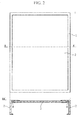
- FIG. 2 contains a top view and a cross-sectional view illustrating a structure of the solar cell panel according to an embodiment of the present invention.
- the cross-sectional view shows the A-A' cross-section of the top view.
- the solar cell panel 1 includes a frame 2, a solar cell panel body 3, and a joint 4.
- the cross-section of the solar cell panel 1 in the direction approximately perpendicular to the A-A' cross-section is the same as that shown by the cross-sectional view of FIG. 2 , except for the length of the solar cell panel body 3.
- the solar cell panel body 3 includes a substrate and a plurality of solar cells mounted or formed on a first surface of the substrate.
- the plurality of solar cells are, for example, connected to each other in series.
- the solar cells are each composed of a transparent electrode layer, a photoelectric conversion layer, and a back electrode layer laminated in this order.
- Examples of the solar cells include single-layer amorphous silicon thin-film solar cells; crystalline silicon solar cells such as microcrystalline silicon solar cells; silicon-germanium solar cells; and other thin-film solar cells such as multijunction (tandem) solar cells in which one to several layers of amorphous silicon solar cells and crystalline silicon solar cells or silicon-germanium solar cells are laminated.
- the solar cell panel body 3 may be one formed by bonding crystalline solar cells onto the first surface of the substrate.
- the frame 2 has an approximately L-shaped cross-section and surrounds the solar cell panel body 3.
- the frame 2 can be formed of, for example, a metal such as aluminum.
- This frame 2 has the approximately L-shaped cross-section instead of the approximately angular-U shaped cross-section in the conventional technology shown in FIG. 1 , and therefore does not have a portion where moisture remains, such as the angular-U-shaped portion. That is, since the periphery outside the solar cell panel body 3 does not retain any moisture, the influence of moisture on the solar cell panel body 3 is substantially reduced. This improves the weatherability and the long-term reliability of the solar cell panel 1.
- the joint 4 connects the solar cell panel body 3 and the frame 2. That is, the crossbar of the "L-shape" of the approximately L-shaped cross-section of the frame 2 and a second surface, opposite to the first surface, of the substrate are connected by the joint 4.
- the joining is preferably accomplished with an adhesive.
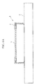
- FIG. 3 is a cross-sectional view illustrating a structure of the joint, and its vicinity, in the solar cell panel according to this embodiment. That is to say, it is an enlarged view of part of the cross-sectional view of FIG. 2 .
- the solar cell panel body 3 includes a substrate 31, a plurality of solar cells 32, a covering layer 33, and a protection layer 34.
- the substrate 31 is translucent and is, for example, a glass substrate. A large substrate having a size of, for example, 1.1 m by 1.4 m by 4 mm t can be used.
- the plurality of solar cells 32 are mounted or formed on a first surface 3a (the surface opposite to the light incident side) of the substrate 31.
- the details of the plurality of solar cells 32 are the same as those described in FIG. 2 , but the periphery 36 of the substrate 31 is not provided with the solar cells 32.
- the periphery 36 is provided mainly for improving adhesion between the covering layer 33 and the substrate 31. Part of the covering layer 33 at the periphery 36 is not covered with the protection layer 34.
- the second surface 3b of the substrate 31 is connected to the frame 2 via the joint 4.
- the covering layer 33 is provided so as to cover the substrate 31 and the plurality of solar cells 32 for protecting their surfaces without forming unnecessary space at the first surface 3a side of the substrate 31.
- the covering layer 33 may be a film made of a resin such as EVA (ethylenevinyl acetate).
- the protection layer 34 is provided so as cover the covering layer 33 disposed on the plurality of solar cells 32 at the first surface 3a side of the substrate 31 for waterproofing.
- the protection layer (back sheet) 34 may be a resin film containing a metal foil inside, such as PAP (PET (poly ethylene terephthalate)/Al foil/PET), for waterproofing.
- the frame 2 includes a frame member 21, an overhang member 23, and a projection member 22.
- the frame member 21 is the vertical bar portion of the "L-shape" of the approximately L-shaped cross-section and is provided so as to surround the outer edge of the solar cell panel body 3.
- the first surface 3a of the substrate 31 and the face extending in the longitudinal direction of the frame member 21 are in approximately a right angle relationship.
- the height t4 and the thickness t1 of the frame member 21 are about 35 mm or more and 50 mm or less and about 2 mm or more and 4 mm or less, respectively, when the frame 2 is made of, for example, aluminum, in consideration of the strength when serving as a frame.
- the IEC standard mentioned here is IEC 61646: 1996, “Thin-film terrestrial photovoltaic (PV) modules Design qualification and type approval”.
- This IEC standard is also a JIS standard: JIS C 8991: 2004 (IEC 61646: 1996), "Thin-film terrestrial photovoltaic (PV) modules - Requirements for design qualification and type approval".
- the overhang member 23 is a portion corresponding to the crossbar portion of the "L-shape" of the approximately L-shaped cross-section and is connected to the frame member 21 at substantially a right angle so as to protrude toward the inside of the frame member 21.
- the overhang member 23 has a thickness t10 and protrudes by a length t2 from the frame member 21.
- the thickness t10 is preferably as small as possible. If the thickness is large, dirt and dust easily gather near a region where the end of the overhang member 23 and the second surface 3b of the substrate 31 meet each other. In such a case, a shadow falls on that region, which adversely affects the power generation. However, because a smaller thickness causes a decrease in the strength, a lower limit of the thickness is determined. For example, in the case of the aluminum frame 2, the thickness t10 is about 2 mm or more and 4 mm or less.
- the length t2 is determined by the relationship with the solar cells 32 of the solar cell panel body 3. On this occasion, the length t2 is preferably determined such that the periphery 36, where cell films are not provided, is shielded so as not to form a shadow on an effective power-generating area contributing to power generation among the cell films of the solar cells 32, but not to expose the covering layer 33 and the protection layer 34 to light through the periphery 36.
- the lower limit of the joint width d1 of the substrate 31 and the overhang member 23 is determined such that the solar cell panel body 3 is held with sufficient joining (adhesion).
- the joint width d1 is determined such that a region where a shadow of the overhang member 23 falls on the substrate 31 is narrow (the shadow of the overhang member 23 does not reach the region where the solar cells 32 are disposed) and that the joining strength is not excessively high and the stress due to the difference in thermal expansion of the substrate 31 and the overhang member 23 is small.
- the width d1 is, for example, about 5 mm or more and 10 mm or less in the case of the aluminum frame 2.
- the lower limit of the distance d2 from the end of the frame member 21 to the end of the solar cell panel body 3 is determined such that the difference in thermal expansion of the frame 2 and the substrate 31 can be absorbed and a distance d4 described below can be secured.
- the upper limit of the distance d2 is determined in consideration of workability, as well as the material costs of a filling portion 42 formed from the end of the frame member 21 to the end of the solar cell panel body 3.
- the distance d2 is, for example, about 1 mm or more in the case of the aluminum frame 2.
- the lower limit of the distance d3 between the end of the solar cells 32 and the end of the overhang member 23 is determined to form a positional relationship such that the shadow of the overhang member 23 does not fall on the solar cells 32, as far as possible, when light is incident on the substrate 31.
- the upper limit of the distance d3 is determined such that the region where the solar cells 32 are not disposed on the substrate 31 is as small as possible.
- the distance d3 is preferably determined such that the periphery 36, where cell films are not provided, is shielded so as not to form a shadow on an effective power-generating area contributing to power generation among the cell films of the solar cells 32, but not to expose the covering layer 33 and the protection layer 34 to light through the periphery 36.
- the projection member 22 is connected to the frame member 21 at substantially a right angle so as to protrude toward the inside of the frame member 21 at the other end of the frame member 21 with respect to the connecting portion of the overhang member 23.
- the projection member 22 protrudes by a length t3.
- the length of the projection member 22 is shorter than that of the overhang member 23, that is, length t2 > length t3.
- a shape-maintaining portion 102-3 corresponding to the projection member 22 functions as a strength-enhancing member for reducing widening of the frame 102.
- the projection member 22 is not required to have a shape that protrudes by a large amount as in the shape-maintaining portion 102-3. This can reduce the cost.
- the projection member 22 should have a certain length t3 for the stability of the frame 2. The length t3 is, for example, about 3 mm or more in the case of the aluminum frame 2.
- the distance d4 between the end of the solar cell panel body 3 and the end of the projection member 22 is, for example, about 0 mm or more, in the case of the aluminum frame 2.
- This distance is determined such that the solar cell panel body 3 is automatically disposed inside of the completed frame 2 with an automated alignment apparatus. That is, because a solar cell panel can be fabricated merely by putting the solar cell panel body on the completed frame 2, this process can be automated.
- the frame is assembled on the solar cell panel body by setting each edge of the solar cell panel body 3 in the respective sides of the frame. This setting cannot be automated due to, for example, undulation or distortion of the substrate. Consequently, this process is manually conducted. In the present invention, this process can be automated, therefore improving the manufacturing efficiency and through-put and allowing a reduction in costs.
- the joint 4 includes an adhesion portion 41, a filling portion 42, and a sealing portion 43.
- the adhesion portion 41 bonds the second surface 3b of the substrate 31, opposite to the first surface 3a, and the surface 23b of the overhang member 23, facing the second surface 3b.
- the lower limit of the thickness d5 of the adhesion portion 41 is determined in consideration of the adhesion strength, and the upper limit is determined in consideration of, for example, material costs. Furthermore, the thickness d5 is preferably larger than half of the difference between thermal elongation of the substrate 31 of the solar cell panel body 3 and that of the frame 2.
- this difference in the thermal elongation is calculated based on the long sides of the rectangle, between a temperature (example: 25°C) when assembled (adhesion) and a highest temperature (example: 85°C) when used outdoors.
- a temperature example: 25°C
- a highest temperature example: 85°C
- the thickness d5 is within the above-mentioned range, provided that the adhesive at the adhesion portion 41 bent by 45 degrees.
- the thickness is, for example, about 1 mm or more in the case of the aluminum frame 2.
- the filling portion 42 is provided so as to fill the recess 45 surrounded by the end of the solar cell panel body 3, the adhesion portion 41, and the frame 2. This prevents moisture from entering and remaining in the recess 45, which significantly reduces deterioration of the solar cell panel body 3 due to moisture. In addition, since the upper portion of the filling portion 42 is further exposed to the outside air, hydroscopic water (moisture) evaporates more readily even if the hydroscopic water (moisture) adheres to this portion.
- the sealing portion 43 is disposed on the filling portion 42 so as to cover the end of the solar cell panel body 3. This end is a portion of the covering layer 33 which is not covered with the protection layer 34. Since the end is not provided with the solar cells 32, light is directly incident on the covering layer 33 near the end without being absorbed in the solar cells 32. Consequently, the covering layer 33 at this portion is relatively easily deteriorated, and infiltration of hydroscopic water (moisture) from the outside easily occurs as the deterioration proceeds.
- the sealing portion 43 protects this portion and the vicinity thereof from the hydroscopic water (moisture). In addition, since the upper portion of the sealing portion 43 is further exposed to the outside air, hydroscopic water (moisture) evaporates more readily even if the hydroscopic water (moisture) adheres to this portion.
- the adhesive of the adhesion portion 41 is an elastic adhesive having weatherability.
- examples of such an adhesive include polyurethane, silicone, and silyl group-containing polymers.
- a specific example is "Super X" (trade name) manufactured by Cemedine Co., Ltd.
- the adhesive used for the adhesion portion 41 can be used as the filling portion 42 and the sealing portion 43 by applying an excess amount of the adhesive or overcoating the adhesive. In such a case, the process is simplified compared to the case where different kinds of materials are applied.
- the filling portion 42 and the sealing portion 43 may be made of materials that are used in the conventional technology.
- Examples of the materials of the filling portion 42 and the sealing portion 43 include polyurethane, silicone, and silyl group-containing polymers.
- breakage at the adhesion portion 41 may be caused by a difference in thermal expansion of the two, or both ends of the solar cell panel body 3 may be deformed as a result of being restrained by the frame 2 if the temperature of only the solar cell panel body 3 is increased.
- the adhesion portion 41 is made of an elastic adhesive, this elastic adhesive absorbs the difference in the thermal elongation. Therefore, breakage at part of the adhesion portion 41 and the deformation of the solar cell panel body 3 are significantly reduced. As a result, stable joining can be maintained.
- the frame 2 is bonded to the substrate 31 of the solar cell panel body 3 with an adhesive. That is, the frame 2 is bonded to the second surface 3b of the substrate 31 of the solar cell panel body 3, which enhances adhesion reliability compared to that in the conventional cases.
- FIGS. 4A to 4D are cross-sectional views illustrating an example of the method of fabricating the solar cell panel according to this embodiment.
- FIGS. 4A to 4D show the A-A' cross-section of FIG. 2 .
- a frame 2 which is described in FIGS. 2 and 3 , is formed (prepared) by assembling it. That is, the frame 2 is not assembled by attaching each member of the frame 2 to the solar cell panel body 3, but is assembled in advance. Accordingly, this process including the assembling of the frame 2 can be easily conducted automatically with a prescribed manufacturing apparatus.
- the above-mentioned polyurethane serving as the adhesive 44 is applied to the overhang member 23.
- the overhang member 23 has a flat application face, and the frame member 21 and the projection member 22 have such shapes as not to impede the application (for example, they do not have shapes covering or surrounding the application face). That is, since the frame does not have a shape that impedes the application, such as an approximately angular-U shaped cross-section, this application process of the adhesive 44 can be easily conducted automatically with a prescribed manufacturing apparatus. In addition, the adhesive 44 is automatically and sequentially applied and is hence uniformly applied without unevenness.
- a separately produced solar cell panel body 3 is pressed against the frame 2 with the second surface 3b of the substrate 31 positioned downward.
- the solar cell panel body 3 can be easily inserted into the inside of the assembled frame 2 automatically with a prescribed manufacturing apparatus.
- drying treatment and heating treatment are conducted.
- the adhesion portion 41 is formed, and the solar cell panel body 3 is bonded to the frame 2.
- the bonding is conducted by simply pressing the solar cell panel body 3 into the adhesive 44 continuously and uniformly applied to the flat overhang member 23, and, thereby, the bonding can be easily conducted for the entire interface between the substrate 31 of the solar cell panel body 3 and the overhang member 23 of the frame 2. Therefore, the reliability of the adhesion is significantly increased.
- a sealing agent 46 is applied to fill the gap between the end of the solar cell panel body 3 and the frame 2.
- the sealing agent 46 is applied so as to also cover the covering layer 33 exposed at the periphery 36 of the solar cell panel body 3.
- this application process of the sealing agent 46 can be easily conducted automatically with a prescribed manufacturing apparatus.
- drying treatment and heating treatment are conducted.
- the filling portion 42 and the sealing portion 43 are formed, and the gap near the end of the solar cell panel body 3 is filled to protect the covering layer 33.
- the sealing agent for the sealing portion 43 may be different from that of the filling portion 42. According to the above, the solar cell panel is produced.
- each member of the respective sides of the frame having an approximately angular-U shaped cross-section is manually attached to the solar cell panel body 3. This is because it is very difficult to automatically fit the solar cell panel body into the "angular-U" portion of the approximately angular-U shaped cross-section, due to the influence of, for example, undulation of the substrate of the solar cell panel body and unevenness in the thickness of the covering layer 33.
- a sealing agent or an adhesive is applied to the "angular-U" portion and the solar cell panel body is fitted thereinto, a high-skill technique is required to uniformly apply the sealing agent or the adhesive between the "angular-U" portion and the solar cell panel body. Therefore, in the frame of the conventional technology that has an approximately angular-U shaped cross-section, the process of bonding the frame and the solar cell panel body has not been automated.
- the frame 2 has an approximately L-shaped cross-section instead of the approximately angular-U shaped cross-section
- the frame 2 and the solar cell panel body 3 are bonded and connected to each other by simply pressing the solar cell panel body 3 onto the frame 2 to which the adhesive 44 is applied. That is, the solar cell panel body 3 is not required to be fitted into a member having an approximately angular-U shaped cross-section, and can be bonded to the frame 2 by a simple process of putting the solar cell panel body 3 on the frame 2 having the approximately L-shaped cross-section and pressing it thereto. This allows the process shown in FIGS. 4A to 4D to be automated, which improves productivity.
- the solar cell panel body 3 is fixed only at the face provided with the adhesive 44, the influence of, for example, undulation of the substrate of the solar cell panel body and unevenness in the thickness of the covering layer 33 can be absorbed by the thickness of the adhesive 44.
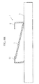
- FIG. 5 is a cross-sectional view illustrating another structure of a joint, and its vicinity, in the solar cell panel according to this embodiment. That is, FIG. 5 is an enlarged view of part of the cross-sectional view in FIG. 2 .
- FIG. 5 is the same as FIG. 3 except that the overhang member 23a becomes thinner with the distance from the connecting portion with the frame member 21. That is, the thickness t11 of the overhang member 23a at the connecting portion with the frame member 21 is larger than the thickness t12 of the overhang member 23a at the end.
- the distance d6 corresponding to the thickness of the adhesion portion 41 can be enlarged compared to the distance d5 in the case shown in FIG. 3 .
- the sum of the thickness t12 and the distance d6 be approximately the same as that of the thickness t10 and the distance d5. If this portion is thicker, dirt and dust easily gather on the substrate 31 at the end of the overhang member 23a, forming a shadow, which adversely affects the power generation.
- the adhesion portion 41 has a relatively large thickness (corresponding to the distance d6), which enhances the elasticity effect of the elastic adhesive used as the adhesion portion 41. That is, it is possible to significantly reduce breakages at the adhesion portion 41 caused by stress due to, for example, a difference in thermal expansion, as well as deformation caused by the stress generated by restraint of both ends of the solar cell panel body 3 by the frame 2, which occur when the frame 2 and the solar cell panel body 3 are strongly joined to each other.
- FIGS. 6A and 6B are cross-sectional views illustrating an installed state of a solar cell panel according to this embodiment.
- the solar cell panel 1 is installed on a rack 5.
- the adhesive at the joint 4 is peeled off, as shown in FIG. 6B , one end of the solar cell panel body 3 is caught on the overhang member 23 of the frame 2, and the other end is prohibited from moving by the rack 5. Consequently, the solar cell panel body 3 does not fall out.
- an insulating sheet such as a PAP sheet is used as an example of the protection layer 34, but the protection layer 34 may be a glass plate. In such a case, the protection layer 34 and the frame 2 may be bonded to each other by placing the solar cell panel body 3 in the opposite orientation.
- a solar cell panel that hardly retains any moisture between the solar cell panel body and the frame is obtained by employing the new frame structure and adhesion structure. This allows an improvement in reliability of the solar cell panel.
- a method of fabricating the solar cell panel that enables automation of the process of attaching the frame to the solar cell panel body is obtained by employing the new frame structure and adhesion structure. Furthermore, the method of fabricating the solar cell panel reduces the number of manufacturing processes and enables easy fabrication of the solar cell panel at lower cost.
Landscapes
- Photovoltaic Devices (AREA)
Applications Claiming Priority (2)
| Application Number | Priority Date | Filing Date | Title |
|---|---|---|---|
| JP2008009995A JP2009170826A (ja) | 2008-01-21 | 2008-01-21 | 太陽電池パネル及び太陽電池パネルの製造方法 |
| PCT/JP2008/067233 WO2009093355A1 (fr) | 2008-01-21 | 2008-09-25 | Panneau solaire et son procédé de fabrication |
Publications (1)
| Publication Number | Publication Date |
|---|---|
| EP2237324A1 true EP2237324A1 (fr) | 2010-10-06 |
Family
ID=40900871
Family Applications (1)
| Application Number | Title | Priority Date | Filing Date |
|---|---|---|---|
| EP08871605A Withdrawn EP2237324A1 (fr) | 2008-01-21 | 2008-09-25 | Panneau solaire et son procédé de fabrication |
Country Status (5)
| Country | Link |
|---|---|
| US (1) | US20100206360A1 (fr) |
| EP (1) | EP2237324A1 (fr) |
| JP (1) | JP2009170826A (fr) |
| CN (1) | CN101765918B (fr) |
| WO (1) | WO2009093355A1 (fr) |
Cited By (1)
| Publication number | Priority date | Publication date | Assignee | Title |
|---|---|---|---|---|
| WO2012167965A1 (fr) | 2011-06-07 | 2012-12-13 | Saint-Gobain Glass France | Module solaire |
Families Citing this family (7)
| Publication number | Priority date | Publication date | Assignee | Title |
|---|---|---|---|---|
| FR2969189A1 (fr) * | 2010-12-15 | 2012-06-22 | Max Dolder | Dispositif support d'element en couverture de toiture et en recouvrement de facade |
| CN103280477B (zh) * | 2013-05-14 | 2015-06-17 | 浙江宏阳新能源科技有限公司 | 一种太阳能电池板 |
| JP6563712B2 (ja) * | 2015-06-25 | 2019-08-21 | ソーラーフロンティア株式会社 | フレーム及びそれを備える太陽電池モジュール |
| JP6491071B2 (ja) * | 2015-10-07 | 2019-03-27 | トヨタ自動車株式会社 | 車載用太陽電池モジュール |
| US20170163210A1 (en) * | 2015-12-08 | 2017-06-08 | Lee Gorny | Photovoltaic module |
| CN105810768B (zh) * | 2016-04-14 | 2017-11-21 | 珠海格力电器股份有限公司 | 双玻组件 |
| JPWO2019220992A1 (ja) * | 2018-05-15 | 2021-07-08 | 住友電気工業株式会社 | 太陽光発電装置の製造方法、太陽光発電装置の製造治具および太陽光発電装置の製造装置 |
Family Cites Families (13)
| Publication number | Priority date | Publication date | Assignee | Title |
|---|---|---|---|---|
| JPH0347335Y2 (fr) * | 1985-06-26 | 1991-10-08 | ||
| JPH0534120Y2 (fr) * | 1986-12-27 | 1993-08-30 | ||
| JPS63188975A (ja) * | 1987-02-02 | 1988-08-04 | Sumitomo Electric Ind Ltd | 太陽電池モジユ−ルの製造方法 |
| JPH0221670A (ja) * | 1988-07-08 | 1990-01-24 | Matsushita Electric Ind Co Ltd | 太陽電池モジュール |
| JPH03265177A (ja) * | 1990-03-15 | 1991-11-26 | Matsushita Electric Ind Co Ltd | 太陽電池モジュール |
| JP2532104Y2 (ja) * | 1991-01-30 | 1997-04-09 | 三洋電機株式会社 | 太陽電池装置 |
| JPH0823116A (ja) * | 1994-07-07 | 1996-01-23 | Sunstar Eng Inc | 太陽電池モジュールとその製造方法 |
| JPH09331079A (ja) | 1996-06-07 | 1997-12-22 | M S K:Kk | フレームレス太陽電池モジュール |
| DE19632493C2 (de) * | 1996-08-12 | 2000-05-18 | Siemens Solar Gmbh | Rahmenloses Solarmodul |
| JP2000297501A (ja) * | 1999-02-10 | 2000-10-24 | Sekisui Chem Co Ltd | 太陽電池付屋根材の取付構造 |
| JP2000349322A (ja) | 1999-06-02 | 2000-12-15 | Shin Etsu Chem Co Ltd | ソーラーハウジング |
| JP2004087884A (ja) | 2002-08-28 | 2004-03-18 | Mitsubishi Heavy Ind Ltd | 太陽電池パネルの支持枠構造 |
| JP4196084B2 (ja) | 2003-06-24 | 2008-12-17 | パナソニック電工株式会社 | 太陽電池モジュールの製造方法 |
-
2008
- 2008-01-21 JP JP2008009995A patent/JP2009170826A/ja not_active Withdrawn
- 2008-09-25 US US12/669,851 patent/US20100206360A1/en not_active Abandoned
- 2008-09-25 CN CN200880100660XA patent/CN101765918B/zh not_active Expired - Fee Related
- 2008-09-25 WO PCT/JP2008/067233 patent/WO2009093355A1/fr not_active Ceased
- 2008-09-25 EP EP08871605A patent/EP2237324A1/fr not_active Withdrawn
Non-Patent Citations (1)
| Title |
|---|
| See references of WO2009093355A1 * |
Cited By (2)
| Publication number | Priority date | Publication date | Assignee | Title |
|---|---|---|---|---|
| WO2012167965A1 (fr) | 2011-06-07 | 2012-12-13 | Saint-Gobain Glass France | Module solaire |
| CN103583000A (zh) * | 2011-06-07 | 2014-02-12 | 法国圣戈班玻璃厂 | 太阳能模块 |
Also Published As
| Publication number | Publication date |
|---|---|
| US20100206360A1 (en) | 2010-08-19 |
| WO2009093355A1 (fr) | 2009-07-30 |
| CN101765918B (zh) | 2011-12-07 |
| CN101765918A (zh) | 2010-06-30 |
| JP2009170826A (ja) | 2009-07-30 |
Similar Documents
| Publication | Publication Date | Title |
|---|---|---|
| EP2237324A1 (fr) | Panneau solaire et son procédé de fabrication | |
| US20090056803A1 (en) | Solar cell module, method for manufacturing the same, solar cell, and method for manufacturing the same | |
| US20090159112A1 (en) | Cis based thin-film photovoltaic module and process for producing the same | |
| US20100243027A1 (en) | Solar cell and solar cell module | |
| US20140137940A1 (en) | Solar cell module and method of manufacturing same | |
| EP4235814B1 (fr) | Module de cellule solaire et son procédé de fabrication | |
| WO2012128342A1 (fr) | Panneau de cellules solaires, module de cellules solaires, et procédé de fabrication de module de cellules solaires | |
| JP5506295B2 (ja) | 太陽電池モジュールおよびその製造方法 | |
| JP2009033130A (ja) | 太陽電池モジュール及び太陽電池モジュールの製造方法 | |
| JP4841156B2 (ja) | 太陽電池モジュール | |
| US20180151768A1 (en) | Solar battery module and method for manufacturing solar battery module | |
| WO2013183395A1 (fr) | Module de batterie solaire et procédé de fabrication de module de batterie solaire | |
| EP2320472B1 (fr) | Module de cellules solaires | |
| JP6087164B2 (ja) | 太陽電池モジュール及び太陽電池モジュールの製造方法 | |
| JP2020088268A (ja) | 太陽電池モジュール | |
| JP4069405B2 (ja) | 太陽電池モジュールの製造方法 | |
| JP3785263B2 (ja) | 太陽電池モジュールおよびその製造方法 | |
| CN217468456U (zh) | 光伏组件及光伏电站 | |
| JP2005175236A (ja) | 太陽電池モジュール | |
| JP5617690B2 (ja) | 太陽電池モジュールの製造方法及び太陽電池モジュール | |
| JP2007201291A (ja) | 太陽電池モジュールの再生方法及び太陽電池モジュール | |
| KR102795429B1 (ko) | 원통형 플렉서블 태양광 모듈 및 그 원통형 플렉서블 태양광 모듈의 제조방법 | |
| KR102885769B1 (ko) | 건물 일체형 태양광 모듈 | |
| JP2002373998A (ja) | 太陽電池モジュールとその製造方法 | |
| JP4132023B2 (ja) | 太陽電池モジュール |
Legal Events
| Date | Code | Title | Description |
|---|---|---|---|
| PUAI | Public reference made under article 153(3) epc to a published international application that has entered the european phase |
Free format text: ORIGINAL CODE: 0009012 |
|
| 17P | Request for examination filed |
Effective date: 20100125 |
|
| AK | Designated contracting states |
Kind code of ref document: A1 Designated state(s): AT BE BG CH CY CZ DE DK EE ES FI FR GB GR HR HU IE IS IT LI LT LU LV MC MT NL NO PL PT RO SE SI SK TR |
|
| AX | Request for extension of the european patent |
Extension state: AL BA MK RS |
|
| DAX | Request for extension of the european patent (deleted) | ||
| STAA | Information on the status of an ep patent application or granted ep patent |
Free format text: STATUS: THE APPLICATION HAS BEEN WITHDRAWN |
|
| 18W | Application withdrawn |
Effective date: 20120327 |