EP2238415B1 - Flüssiggasmessung unter verwendung eines differentialdruckbasierten durchflussmessers mit einem sonarbasierten durchflussmesser - Google Patents
Flüssiggasmessung unter verwendung eines differentialdruckbasierten durchflussmessers mit einem sonarbasierten durchflussmesser Download PDFInfo
- Publication number
- EP2238415B1 EP2238415B1 EP09700436.0A EP09700436A EP2238415B1 EP 2238415 B1 EP2238415 B1 EP 2238415B1 EP 09700436 A EP09700436 A EP 09700436A EP 2238415 B1 EP2238415 B1 EP 2238415B1
- Authority
- EP
- European Patent Office
- Prior art keywords
- gas
- flow
- pressure
- flowmeter
- gas flow
- Prior art date
- Legal status (The legal status is an assumption and is not a legal conclusion. Google has not performed a legal analysis and makes no representation as to the accuracy of the status listed.)
- Active
Links
Images






Classifications
-
- G—PHYSICS
- G01—MEASURING; TESTING
- G01F—MEASURING VOLUME, VOLUME FLOW, MASS FLOW OR LIQUID LEVEL; METERING BY VOLUME
- G01F1/00—Measuring the volume flow or mass flow of fluid or fluent solid material wherein the fluid passes through a meter in a continuous flow
- G01F1/05—Measuring the volume flow or mass flow of fluid or fluent solid material wherein the fluid passes through a meter in a continuous flow by using mechanical effects
- G01F1/34—Measuring the volume flow or mass flow of fluid or fluent solid material wherein the fluid passes through a meter in a continuous flow by using mechanical effects by measuring pressure or differential pressure
- G01F1/36—Measuring the volume flow or mass flow of fluid or fluent solid material wherein the fluid passes through a meter in a continuous flow by using mechanical effects by measuring pressure or differential pressure the pressure or differential pressure being created by the use of flow constriction
-
- G—PHYSICS
- G01—MEASURING; TESTING
- G01F—MEASURING VOLUME, VOLUME FLOW, MASS FLOW OR LIQUID LEVEL; METERING BY VOLUME
- G01F1/00—Measuring the volume flow or mass flow of fluid or fluent solid material wherein the fluid passes through a meter in a continuous flow
- G01F1/66—Measuring the volume flow or mass flow of fluid or fluent solid material wherein the fluid passes through a meter in a continuous flow by measuring frequency, phase shift or propagation time of electromagnetic or other waves, e.g. using ultrasonic flowmeters
- G01F1/666—Measuring the volume flow or mass flow of fluid or fluent solid material wherein the fluid passes through a meter in a continuous flow by measuring frequency, phase shift or propagation time of electromagnetic or other waves, e.g. using ultrasonic flowmeters by detecting noise and sounds generated by the flowing fluid
-
- G—PHYSICS
- G01—MEASURING; TESTING
- G01F—MEASURING VOLUME, VOLUME FLOW, MASS FLOW OR LIQUID LEVEL; METERING BY VOLUME
- G01F1/00—Measuring the volume flow or mass flow of fluid or fluent solid material wherein the fluid passes through a meter in a continuous flow
- G01F1/704—Measuring the volume flow or mass flow of fluid or fluent solid material wherein the fluid passes through a meter in a continuous flow using marked regions or existing inhomogeneities within the fluid stream, e.g. statistically occurring variations in a fluid parameter
- G01F1/708—Measuring the time taken to traverse a fixed distance
- G01F1/7082—Measuring the time taken to traverse a fixed distance using acoustic detecting arrangements
-
- G—PHYSICS
- G01—MEASURING; TESTING
- G01F—MEASURING VOLUME, VOLUME FLOW, MASS FLOW OR LIQUID LEVEL; METERING BY VOLUME
- G01F1/00—Measuring the volume flow or mass flow of fluid or fluent solid material wherein the fluid passes through a meter in a continuous flow
- G01F1/704—Measuring the volume flow or mass flow of fluid or fluent solid material wherein the fluid passes through a meter in a continuous flow using marked regions or existing inhomogeneities within the fluid stream, e.g. statistically occurring variations in a fluid parameter
- G01F1/708—Measuring the time taken to traverse a fixed distance
- G01F1/712—Measuring the time taken to traverse a fixed distance using auto-correlation or cross-correlation detection means
-
- G—PHYSICS
- G01—MEASURING; TESTING
- G01F—MEASURING VOLUME, VOLUME FLOW, MASS FLOW OR LIQUID LEVEL; METERING BY VOLUME
- G01F1/00—Measuring the volume flow or mass flow of fluid or fluent solid material wherein the fluid passes through a meter in a continuous flow
- G01F1/74—Devices for measuring flow of a fluid or flow of a fluent solid material in suspension in another fluid
-
- G—PHYSICS
- G01—MEASURING; TESTING
- G01F—MEASURING VOLUME, VOLUME FLOW, MASS FLOW OR LIQUID LEVEL; METERING BY VOLUME
- G01F15/00—Details of, or accessories for, apparatus of groups G01F1/00 - G01F13/00 insofar as such details or appliances are not adapted to particular types of such apparatus
- G01F15/08—Air or gas separators in combination with liquid meters; Liquid separators in combination with gas-meters
Definitions
- a fluid flow process includes any process that involves the flow of fluid through pipes, ducts, or other conduits, as well as through fluid control devices such as pumps, valves, orifices, heat exchangers, and the like.
- Flow processes are found in many different industries such as the oil and gas industry, refining, food and beverage industry, chemical and petrochemical industry, pulp and paper industry, power generation, pharmaceutical industry, and water and wastewater treatment industry.
- the fluid within the flow process may be a single phase fluid (e.g., gas, liquid or liquid/liquid mixture) and/or a multi-phase mixture (e.g. paper and pulp slurries or other solid/liquid mixtures).
- the multi-phase mixture may be a two-phase liquid/gas mixture, a solid/gas mixture or a solid/liquid mixture, gas entrained liquid or a three-phase mixture.
- a separator which is an item of production equipment used to separate liquid components of the fluid stream from gaseous components.
- the liquid and gas components flow from the separator in separate legs (pipes), with the leg containing the gas component referred to as the "gas leg” and the leg containing the liquid component referred to as the "liquid leg".
- Each of the legs typically includes a flow meter to determine the volumetric flow rate for each of the gas and the fluid components, respectively, wherein the volumetric flow rate for the gas leg is commonly measured using an orifice plate.
- US 2007/006744 A1 discloses a method and apparatus for measuring a parameter of a wet gas flow, wherein the apparatus includes a differential pressure based flow meter configured to determine a first volumetric flow rate of the wet gas flow. Additionally, the apparatus includes a sonar based flow meter configured to determine a second volumetric flow rate of the wet gas flow. Furthermore, the apparatus includes a processing device communicated with at least one of the differential pressure base flow meter and the sonar based flow meter, wherein the processing device is configured to determine the parameter (e.g., wetness, volumetric gas flow rate, and volumetric liquid flow rate) of the wet gas flow using the first and second volumetric flow rates.
- the parameter e.g., wetness, volumetric gas flow rate, and volumetric liquid flow rate
- WO 2007/008623 A1 discloses an apparatus for determining a characteristic of a fluid flow within a pipe, wherein the apparatus includes a separating device for separating the fluid into a gas component and a liquid component and directing the gas component to flow within a gas leg portion of the pipe and the liquid component to flow within a liquid portion of the pipe.
- the apparatus includes a gas leg portion metering device for generating gas component data and a liquid leg portion metering device for generating liquid component data.
- the apparatus further includes a processing device communicated with at least one of the gas leg portion metering device and the liquid leg portion metering device, the processing device being configured to receive and process at least one of the gas component data and the liquid component data to generate fluid flow data responsive to a fluid flow characteristic
- the apparatus also includes a second flow meter having an array of sensors configured to determine a second volumetric flow rate of the wet gas flow.
- the apparatus includes a processing device communicated with at least one of the differential pressure base flow meter and the second flow meter, wherein the processing device is configured to determine at least one of the wetness of the wet gas flow, the volumetric flow of the liquid portion of the wet gas flow, and the volumetric flow of the gas portion of the wet gas flow using the first and second volumetric flow rates.
- Differential pressure-based (DP) flowmeters such as venturi type flowmeters, are widely used to monitor gas production and are well-known to over-report the gas flow rates in the presence of liquids, wherein this tendency to over report due to wetness indicates a strong correlation with the liquid to gas mass ratio of the flow.
- the term "differential pressure-based flowmeter” or “DP flowmeter” refers to a device that is operable to determine a pressure drop of a flow of fluid, or gas, or mixture thereof, traveling within a pipe across a constriction within that pipe, or through a flow length of pipe.
- Examples of DP flowmeters that utilize a constriction include, but are not limited to, venturi, orifice, elbow, V-cone, and wedge type flow meters. Additionally, it has been observed that sonar type flowmeters (which do not utilize a constriction within a pipe), as will be described hereinafter, continue to accurately report gas flow rates, independent of the liquid loading. As such, this insensitivity to wetness associated with sonar flow meters provides a practical means for accurately measuring the gas flow rate and the liquid flow rate of a wet gas flow. In the processing of the combined data (i.e.
- a set of local wetness sensitivity coefficients for each wetness series can be used to provide a more accurate characterization for both the DP flowmeter and the sonar flowmeter to determine wetness, wherein the wetness sensitivity coefficients for each device may be provided by a low order polynomial fit of the over-report vs. wetness. This characterization may then be used to "invert" the outputs of the DP flowmeter and the sonar flowmeter to provide an accurate gas flow rate and an accurate liquid flow rate.
- the wetness insensitivity of a sonar flowmeter deteriorates with decreasing densimetric Froude numbers (Fr), wherein the densimetric Froude number is a measure of the degree of "mixedness" in the flow.
- the Froude number is given by, Fr ⁇ ⁇ gas ⁇ liq V gas gD
- Fr is the Froude number
- ⁇ gas is the gas density
- ⁇ liq is the liquid density
- V gas is the flow velocity of the gas
- gD is the force of gravity multiplied by the inner diameter of the pipe.
- FIG. 1 a schematic diagram of a first embodiment of an apparatus 112 for measuring wetness and volumetric flow rates of a wet gas flow 104 flowing within a pipe 124 is shown.
- the apparatus 112 includes a differential pressure based flowmeter 114 (DP flowmeter) and a flowmeter 116 having an array of sensors 118 (sonar flowmeter).
- the DP flowmeter 114 determines the volumetric flow rate (Q ⁇ P ) of the wet gas flow 104.
- the sonar flowmeter 116 determines the volumetric flow rate (Q sonar ) of the wet gas flow 104, which will be described in greater detail herein after.
- a processing unit 116 in response to volumetric flow rates provided by the DP flowmeter 114 and the sonar flowmeter 116, determines at least the wetness, the volumetric flow rate of the gas portion, and the volumetric flow rate of the liquid portion of a wet gas flow within a pipe, which will be described in greater detail hereinafter.
- the sonar flowmeter 116 is disposed downstream of the DP flowmeter 114, which provides a well mixed liquid gas flow 104 to be measured by the sonar flowmeter 116.
- the DP flowmeter may be disposed downstream of the sonar flowmeter as shown in Figure 10 .
- the differential pressure based flowmeter 114 may include any type of flowmeter that enables flow measurement using a differential pressure ( ⁇ P) in the flow 104.
- the DP flowmeter 114 may enable flow measurement by using a flow obstruction 128 or restriction to create a differential of the static pressure of the flow that is proportional to the square of the velocity of the gas flow 104 in the pipe 124, in accordance with Bernoulli's theorem.
- This type of DP flowmeter typically measures a difference in the static pressure of the flow at two axial positions where the difference in pressure is primarily generated by the flow within the pipe moving through a restriction-type flow obstruction.
- the differential pressure across the obstruction 128, using a pair of pressure sensors 113, may be measured and converted into a volumetric flow rate using a processor or secondary device 130, such as a differential pressure transmitter.
- the flow obstruction 128 is an orifice plate 128 through which the wet gas flow 104 passes.
- the transmitter 130 senses the drop in pressure of the flow 104 across the orifice plate 128, and determines a volumetric flow rate of the wet gas flow 104 (Q ⁇ P ) as a function of the sensed pressure drop.
- differential pressure based flow meter 114 may include a venturi meter, an elbow flow meter, a v-cone meter, a pipe constriction or the like.
- the sonar based flowmeter 116 includes a spatial array 132 of at least two pressure sensors 118 disposed at different axial locations x 1 ... x N along the pipe 124. Each of the pressure sensors 118 provides a pressure signal P(t) indicative of unsteady pressure within the pipe 124 at a corresponding axial location x 1 ... x N of the pipe 124.
- a signal processor 134 receives the pressure signals P 1 (t) ... P N (t) from the pressure sensors 118 in the array 132, and determines the velocity and volumetric flow rate of the wet gas flow 104 using pressure signals from the pressure sensors 118. The signal processor 134 then applies array-processing techniques to the pressure signals P 1 (t) ... P N (t) to determine the velocity, volumetric flow rate, and/or other parameters of the wet gas flow 104.
- the sonar based flowmeter 116 is shown as including four pressure sensors 118, it is contemplated that the array 132 of pressure sensors 118 may include two or more pressure sensors 118, each providing a pressure signal P(t) indicative of unsteady pressure within the pipe 124 at a corresponding axial location X of the pipe 124.
- the sonar based flowmeter 116 may include 2, 3, 4, 5, 6, 7, 8, 9, 10, 11, 12, 13, 14, 15, 16, 17, 18, 19, 20, 21, 22, 23, or 24 pressure sensors 118.
- the accuracy of the measurement improves as the number of sensors 118 in the array 132 increases.
- the degree of accuracy provided by the greater number of sensors 118 is offset by the increase in complexity and time for computing the desired output parameter of the flow. Therefore, the number of sensors 118 used is dependent at least on the degree of accuracy desired and the desire update rate of the output parameter provided by the meter 116.
- the signals P 1 (t) ... P N (t) provided by the pressure sensors 118 in the array 132 are processed by the signal processor 134, which may be part of the larger processing unit 120.
- the signal processor 134 may be a microprocessor and the processing unit 120 may be a personal computer or other general purpose computer. It is contemplated that the signal processor 134 may be any one or more analog or digital signal processing devices for executing programmed instructions, such as one or more microprocessors or application specific integrated circuits (ASICS), and may include memory for storing programmed instructions, set points, parameters, and for buffering or otherwise storing data.
- ASICS application specific integrated circuits
- flow logic 136 may be implemented in software (using a microprocessor or computer) and/or firmware, or may be implemented using analog and/or digital hardware, having sufficient memory, interfaces, and capacity to perform the functions described herein.
- the signal processor 134 applies the data from the pressure sensors 118 to flow logic 136 which is executed by the signal processor 134.
- the flow logic 136 is described in further detail hereinafter. It is also contemplated that one or more of the functions performed by the secondary device 130 of the differential pressure flowmeter 114 may be performed by the signal processor 134. For example, signals indicative of gas flow pressure upstream and downstream of the orifice 128 may be provided to the signal processor 134, and the signal processor 134 may determine the volumetric flow rate Q ⁇ P .
- the signal processor 134 can determine the wetness, the volumetric flow rate of the gas portion, and the volumetric flow rate a the liquid portion of the flow 104.
- the Lockhardt Martinelli (LM) number is defined as the square root of the ratio of the product of liquid mass flow times the liquid volumetric flow to the product of the gas mass flow times the gas volumetric flow and is given by, LM ⁇ m ⁇ liq Q liq m ⁇ gas Q gas ⁇ ⁇ liq Q liq 2 ⁇ gas Q gas 2 ⁇ ⁇ liq ⁇ gas Q liq Q gas wherein ⁇ liq is the liquid mass flow, Q liq is the liquid volumetric flow, ⁇ liq is the density of the liquid, ⁇ gas is the gas mass flow, Q gas is the gas volumetric flow, and ⁇ gas is the density of the gas.
- LM Lockhardt Martinelli
- the differential pressure based flowmeter 114 will over report the volumetric flow rate of the gas flow 104 by a ratio of 1+ ⁇ LM as compared to the volumetric flow reported for an equivalent volume flow rate of dry gas.
- Figure 5 depicts a plot of this over reporting (over-reading) of an Emerson Model 1595 orifice based flow meter as a function of the LM number and as shown, the over reporting scales linearly with the LM number.
- the sonar flowmeter 116 and the differential flowmeter (“DP meter") 114 will report the same flow rates for dry gases, and will report diverging flow rates with increasing wetness.
- the combination of the volumetric flow rates Q ⁇ P and Q sonar from the differential pressure based flowmeter 114 and sonar based flowmeter 116 provide a measure of both the flow rate and the wetness of a gas continuous flow 104, which can be determined by the signal processor 134 using the equations:
- ⁇ is an empirically determined wetness sensitivity coefficient that may be introduced by various factors, such as environmental factors (i.e.
- a calibration point can be added by equating the outputs of the differential pressure based flowmeter 114 and sonar based flowmeter 116 during flow conditions where the gas is known to be dry.
- the LM number may be determined using the measured volumetric flow rates (i.e., Q ⁇ P and Q SONAR ) measured by the DP flowmeter 114 and the sonar flowmeter 116, respectively, using Eqn. 4b. Knowing the LM number and the density of the gas and liquid, the volumetric flow rate of the liquid may be determined using Eqn. 2 and Eqn. 3.
- over-reporting may be defined as the linear function 1 + ⁇ LM
- the over-reporting can be defined as any function suitable to the desired end purpose, such as a linear, quadratic, polynomial and/or logarithmic function that defines an over-reporting characteristics of the meters which will be described in greater detail hereinafter.
- any over-reporting function may be used that accurately fits the output of the flowmeters 114, 116 over the desire range of LM numbers (e.g., curve fitting).
- the signal processor 134 may output the LM number, the volumetric flow rates Q ⁇ P and/or Q sonar, , velocity of the gas and liquid portions, or any combination thereof, as well as various other parameters that may be determined from these values as a signal 138.
- the signal 138 may be provided to a display 140, another input/output (I/O) device 142 or another processing device for further processing.
- the I/O device 142 may also accept user input parameters 144 as may be necessary for the flow logic 136.
- the I/O device 142, display 140, and/or signal processor 134 unit may be mounted in a common housing, which may be attached to the array 132 by a flexible cable, wireless connection, or the like. The flexible cable may also be used to provide operating power from the processing unit 120 to the array 132 if necessary.
- the relationship of the LM number to the output of the DP flowmeter 114 (Q ⁇ P ) and the sonar flowmeter 116 (Q SONAR ) as described hereinbefore is graphically illustrated in Figure 2 .
- the difference 400 between the volumetric flow rate 402 of the DP flowmeter 114 and the volumetric flow rate 404 of the sonar flowmeter 116 is related to the wetness of the gas flow 104, and is given by 1+ ⁇ LM.
- the sonar flowmeter 116 provides an output signal representative of the velocity or flow rate of the gas to be used in the determination of the wetness
- the invention contemplates that any other output of the sonar meter 116, which is insensitive to wetness, may be used to determine the wetness of the gas.
- a block diagram 300 describes an example of an algorithm for determining at least one of the wetness, volumetric liquid flow rate, and volumetric gas flow rate of the wet gas 104 flowing in the pipe 124.
- An output function of each of the flowmeters 114, 116 is provided that is dependent on a non-dimensional parameter relating to the wetness of the flow 104, as shown in operational block 302.
- the non-dimensional parameter e.g., LM number and liquid to gas mass flow ratio (MR or LGMR)
- MR or LGMR liquid to gas mass flow ratio
- the over-reporting of the sonar meter may be defined as 1 + ⁇ MR and the over-reporting of the DP meter (e.g., venturi meter) may be defined as 1 + ⁇ MP + ⁇ MR 2 , one will appreciate that the invention contemplates that the over-reporting can be defined as any function suitable to the desired end purpose, such as a linear, quadratic, polynomial and/or logarithmic function that defines an over-reporting characteristics of the meters which will be described in greater detail hereinafter.
- Q SONAR is shown as being defined by the function in Eqn. 5 and Q Venturi is shown as being defined by the function in Eqn. 6, it should be appreciated that Q SONAR and Q Venturi may be defined by any function suitable to the desired end purpose, such as a linear, quadratic, polynomial and/or logarithmic function that defines an over-reporting characteristic of the meter(s) as will be described in greater detail hereinafter.
- any over-reporting function may be used that accurately fits the output of the flowmeters 114, 116 over the desire range of MRs (e.g., curve fitting).
- the relationship of the MR to the output of the DP flowmeter 114 (Q ⁇ P ) and the sonar flowmeter 116 (Q SONAR ) as described hereinbefore is graphically illustrated in Figure 4 .
- the difference 410 between the volumetric flow rate 412 of the DP flowmeter 114 and the volumetric flow rate 414 of the sonar flowmeter 116 is relative to the wetness of the gas flow 104, and is given by the difference of 1+ ⁇ MR + ⁇ MR 2 and 1+ ⁇ MR.
- the sonar flowmeter 116 provides an output signal representative of the velocity or volumetric flow rate of the gas to be used in the determination of the wetness
- the invention contemplates that any other output of the sonar flowmeter 116, which is insensitive to wetness may be used to determine the wetness of the gas.
- the DP flowmeter 114 is described herein as being a venturi meter, the invention contemplates that any other type of DP flowmeter suitable to the desired end purpose may be used.
- the present invention contemplates that the characteristics may be defined by any other output measured by the flow meters, such as the flow velocity, provided the sensitivity of the outputs to wetness are comparable to the sensitivity of the measured volumetric flow rate.
- the measured parameter of the DP flowmeter 114 is sensitive to wetness and the measured output of the sonar flowmeter 116 is relatively insensitive to wetness of the flow 104.
- the present invention defines the outputs of the DP flowmeter 114 and the sonar flowmeter 116 as a respective formula to be solved, it will be appreciated that the data may be provided in the form of a look-up table to provide a number for a non-dimensional parameter (e.g., LM number, MR), the volumetric liquid flow rate and volumetric gas flow rate of the flow 104 in response to the measured parameters (velocity, volumetric flow) of the flowmeters 114, 116.
- a non-dimensional parameter e.g., LM number, MR
- the apparatus 112 is shown wherein the wet gas mixture 104 is directed to flow in a gas leg portion 108 of a separator 102 and the liquid 106 is directed to flow in a liquid leg portion 110 of the separator 102.
- the gas mixture 104 flowing in the gas leg 108 includes gas and liquid carry-over from the separator 102.
- the fluid flow 100 is shown being introduced into a separator 102 which separates the fluid flow 100 into a gas mixture 104 and a liquid 106, wherein the gas mixture 104 is directed to flow in a gas leg portion 108 of the separator 102 and the liquid 106 is directed to flow in a liquid leg portion 110 of the separator 102.
- the gas mixture 104 flowing in the gas leg 108 includes gas and liquid carry-over from the separator 102.
- An apparatus 112 is provided to measure the wetness and flow rate of the gas mixture 104 and may include a differential pressure flowmeter ("DP flowmeter") 114 and a sonar flowmeter 116 having an array of strain-based sensors 118, wherein the combination of the DP flowmeter 114 and the sonar flowmeter 116 provides flow rate measurements to a separator outflow processor 120.
- DP flowmeter differential pressure flowmeter
- sonar flowmeter 116 having an array of strain-based sensors 118
- the separator outflow processor 120 determines the wetness of the gas mixture 104 in the gas leg 108 as well as, the volumetric flow rate of the gas, and the volumetric flow rate of the liquid carry-over.
- the volumetric flow rate of the components of the liquid carry-over i.e. oil and water
- the gas/liquid separator 102 is an item of production equipment used to separate liquid components of an incoming fluid stream 100 from any gaseous components.
- the liquid and gas components flow from the separator 102 in separate pipes (legs) 124 and 126; leg 124 contains the gas component 104 and leg 126 contains the liquid component 106.
- the liquid leg 126 may include the liquid flowmeter 122, which measures the volumetric flow rate of the liquid 106 flowing there through.
- the separator 102 is depicted as a vertical vessel, the gas/liquid separator 102 may be any device for separating gas from one or more liquids.
- the separator 102 may include a cylindrical or spherical vessel, and may be either horizontally or vertically positioned.
- the separator 102 may use gravity segregation, centrifugal separation, cyclone separation, or any other known means to accomplish the separation, and may include one or more stages.
- the sonar flowmeter 116 may comprise a plurality of ultrasonic sensors 118 to provide an output signal, for example a velocity measurement.
- the ultrasonic sonar flowmeter 116 is similar to that described in U.S. Patent Application No. 10/756,977 (Atty Docket No. CC-0700) filed on January 13, 2004 and U.S. Patent No. 7,237,440 .
- the sensors 118 may also include electrical strain gages, optical fibers and/or gratings, ported sensors, among others as described herein, and may be attached to the pipe 124 by adhesive, glue, epoxy, tape or other suitable attachment means to ensure suitable contact between the sensor and the pipe 124. Additionally, the sensors 118 may alternatively be removable or permanently attached via known mechanical techniques such as mechanical fastener, spring loaded, clamped, clam shell arrangement, strapping or other equivalents. Alternatively, strain gages, including optical fibers and/or gratings, may be embedded in a composite pipe 124. If desired, for certain applications, gratings may be detached from (or strain or acoustically isolated from) the pipe 124 if desired. It is also contemplated that any other strain sensing technique may be used to measure the variations in strain in the pipe 124, such as highly sensitive piezoelectric, electronic or electric, strain gages attached to or embedded in the pipe 124.
- a piezo-electronic pressure transducer may be used as one or more of the pressure sensors 118 and it may measure the unsteady (or dynamic or ac) pressure variations inside the pipe 124 by measuring the pressure levels inside the pipe 124.
- the sensors 118 comprise pressure sensors manufactured by PCB Piezotronics of Depew, New York.
- the sensors 118 there are integrated circuit piezoelectric voltage mode-type sensors that feature built-in microelectronic amplifiers, and convert the high-impedance charge into a low-impedance voltage output.
- a Model 106B manufactured by PCB Piezotronics which is a high sensitivity, acceleration compensated integrated circuit piezoelectric quartz pressure sensor suitable for measuring low pressure acoustic phenomena in hydraulic and pneumatic systems. It has the unique capability to measure small pressure changes of less than 0.001 psi under high static conditions.
- the Model 106B has a 300 mV/psi sensitivity and a resolution of 91 dB (0.0001 psi).
- the sensors 118 may incorporate a built-in MOSFET microelectronic amplifier to convert the high-impedance charge output into a low-impedance voltage signal.
- the sensors 118 may be powered from a constant-current source and can operate over long coaxial or ribbon cable without signal degradation.
- the low-impedance voltage signal is not affected by triboelectric cable noise or insulation resistance-degrading contaminants.
- Power to operate integrated circuit piezoelectric sensors generally takes the form of a low-cost, 24 to 27 VDC, 2 to 20 mA constant-current supply.
- piezoelectric pressure sensors are constructed with either compression mode quartz crystals preloaded in a rigid housing, or unconstrained tourmaline crystals. These designs give the sensors microsecond response times and resonant frequencies in the hundreds of kHz, with minimal overshoot or ringing. Small diaphragm diameters ensure spatial resolution of narrow shock waves.
- the output characteristic of piezoelectric pressure sensor systems is that of an AC-coupled system, where repetitive signals decay until there is an equal area above and below the original base line. As magnitude levels of the monitored event fluctuate, the output remains stabilized around the base line with the positive and negative areas of the curve remaining equal.
- each of the sensors 118 may include a piezoelectric sensor that provides a piezoelectric material to measure the unsteady pressures of the flow 104.
- the piezoelectric material such as the polymer, polarized fluoropolymer, PVDF, measures the strain induced within the process pipe 124 due to unsteady pressure variations within the flow 104. Strain within the pipe 124 is transduced to an output voltage or current by the attached piezoelectric sensors 118.
- each piezoelectric sensor 118 may be adhered to the outer surface of a steel strap that extends around and clamps onto the outer surface of the pipe 124.
- the piezoelectric sensing element is typically conformal to allow complete or nearly complete circumferential measurement of induced strain.
- the sensors can be formed from PVDF films, co-polymer films, or flexible PZT sensors, similar to that described in " Piezo Film Sensors technical Manual” provided by Measurement Specialties, Inc. of Fairfield, New Jersey .
- the advantages of this technique include the following:
- Each sensor 118 provides a signal indicating an unsteady pressure at the location of each sensor 118, at each instant in a series of sampling instants.
- the array 132 may include more than two sensors 118 distributed at locations x 1... x N .
- the pressure generated by the convective pressure disturbances may be measured through the sensors 118, which may be strained-based sensors and/or pressure sensors.
- the sensors 118 provide analog pressure time-varying signals P 1 (t), P 2 (t), P 3 (t) ... P N (t) to the signal processor 134, which in turn applies these signals P 1 (t), P 2 (t), P 3 (t) ... P N (t) to the flow logic 136.
- the flow logic 136 processes the signals P 1 (t), P 2 (t), P 3 (t) ...
- P N (t) to first provide output signals (parameters) indicative of the pressure disturbances that convect with the fluid (gas) 104, and subsequently, provide output signals in response to pressure disturbances generated by convective waves propagating through the fluid 104, such as velocity, Mach number and volumetric flow rate of the fluid 104.
- the signal processor 134 includes data acquisition unit 148 (e.g., A/D converter) that converts the analog signals P 1 (t)...P N (t) to respective digital signals and provides the digital signals P 1 (t)...P N (t) to FFT logic 150.
- the FFT logic 150 calculates the Fourier transform of the digitized time-based input signals P 1 (t)...P N (t) and provides complex frequency domain (or frequency based) signals P 1 ( ⁇ ),P 2 ( ⁇ ),P 3 ( ⁇ ), ... P N ( ⁇ ) indicative of the frequency content of the input signals to a data accumulator 152.
- any other technique for obtaining the frequency domain characteristics of the signals P 1 (t) - P N (t) may also be used.
- the cross-spectral density and the power spectral density may be used to form a frequency domain transfer functions (or frequency response or ratios) discussed hereinafter.
- One technique of determining the convection velocity of the turbulent eddies 146 within the fluid 104 is by characterizing a convective ridge (154 in Figure 9 ) of the resulting unsteady pressures using an array of sensors or other beam forming techniques, similar to that described in U.S Patent No. 6,889,562 and U.S. Patent No. 6,609,069 .
- the data accumulator 152 accumulates the frequency signals P 1 ( ⁇ ) - P N ( ⁇ ) over a sampling interval, and provides the data to an array processor 156, which performs a spatial-temporal (two-dimensional) transform of the sensor data, from the xt domain to the k- ⁇ domain, and then calculates the power in the k- ⁇ plane, as represented by the k- ⁇ plot shown in Figure 9 .
- the array processor 156 uses standard so-called beam forming, array processing, or adaptive array-processing algorithms, i.e. algorithms for processing the sensor signals using various delays and weighting to create suitable phase relationships between the signals provided by the different sensors, thereby creating phased antenna array functionality.
- the prior art teaches many algorithms for use in spatially and temporally decomposing a signal from a phased array of sensors, and the present invention is not restricted to any particular algorithm.
- One particular adaptive array processing algorithm is the Capon method/algorithm. While the Capon method is described as one method, the present invention contemplates the use of other adaptive array processing algorithms, such as MUSIC algorithm.
- the present invention recognizes that such techniques can be used to determine flow rate, i.e. that the signals caused by a stochastic parameter convecting with a flow are time stationary and have a coherence length long enough that it is practical to locate sensor units apart from each other and yet still be within the coherence length.
- k ⁇ / u
- u the convection velocity (flow velocity).
- a plot of k- ⁇ pairs obtained from a spectral analysis of sensor samples associated with convective parameters portrayed so that the energy of the disturbance spectrally corresponding to pairings that might be described as a substantially straight ridge, a ridge that in turbulent boundary layer theory is called a convective ridge.
- What is being sensed are not discrete events of turbulent eddies, but rather a continuum of possibly overlapping events forming a temporally stationary, essentially white process over the frequency range of interest.
- the convective eddies 146 are distributed over a range of length scales and hence temporal frequencies.
- the array processor 156 determines the wavelength and so the (spatial) wavenumber k, and also the (temporal) frequency and so the angular frequency ⁇ , of various of the spectral components of the stochastic parameter.
- the array processor 156 determines the wavelength and so the (spatial) wavenumber k, and also the (temporal) frequency and so the angular frequency ⁇ , of various of the spectral components of the stochastic parameter.
- the present invention may use temporal and spatial filtering to precondition the signals to effectively filter out the common mode characteristics P common mode and other long wavelength (compared to the sensor spacing) characteristics in the pipe 124 by differencing adjacent sensors 118 and retain a substantial portion of the stochastic parameter associated with the flow field and any other short wavelength (compared to the sensor spacing) low frequency stochastic parameters.
- suitable turbulent eddies 146 see Figure 8
- the power in the k- ⁇ plane shown in the k- ⁇ plot of Figure 9 shows a convective ridge 154.
- the convective ridge 154 represents the concentration of a stochastic parameter that convects with the flow and is a mathematical manifestation of the relationship between the spatial variations and temporal variations described above. Such a plot will indicate a tendency for k- ⁇ pairs to appear more or less along a line 154 with some slope, the slope indicating the flow velocity.
- a convective ridge identifier 158 uses one or another feature extraction method to determine the location and orientation (slope) of any convective ridge 154 present in the k- ⁇ plane.
- a so-called slant stacking method is used, a method in which the accumulated frequency of k- ⁇ pairs in the k- ⁇ plot along different rays emanating from the origin are compared, each different ray being associated with a different trial convection velocity (in that the slope of a ray is assumed to be the flow velocity or correlated to the flow velocity in a known way).
- the convective ridge identifier 158 provides information about the different trial convection velocities, information referred to generally as convective ridge information to an analyzer 160.
- the volumetric flow is determined by multiplying the cross-sectional area of the inside of the pipe 124 with the velocity of the process flow.
- the present invention contemplates that the sonar flow meter 116 may be substituted with an ultrasonic flow meter similar to any one of the following types of meters: Transit Time Ultrasonic Flow Meter (TTUF), Doppler Ultrasonic Flowmeter (DUF), and Cross Correlation Ultrasonic Flow Meter (CCUF), similar to that described in the article " Guidelines for the Use of Ultrasonic Non-Invasive Metering Techniques" by M.L. Sanderson and H.Yeung, published on July 17, 2002 , which incorporated herein by reference.
- CCUF is manufactured by GE Panametrics DigitalFlow TM CTF878 flowmeter having a pair of ultrasonic sensors disposed axially along the pipe.
- the method of the present invention provides for a flow measurement that is very insensitive to wetness, such as that provided by the sonar flowmeter 116. As such, the present invention allows for a greater difference in the over reporting between the sonar flowmeter 116 and the DP flowmeter 114 which translates into measurements that have a greater accuracy and resolution than existing methods.
- the pipe 124 is depicted as the gas leg 108 of the gas/liquid separator 102, it is contemplated that the apparatus 112 may be used on any duct, conduit or other form of pipe 124 through which a gas 104 may flow.
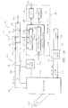
- the wet/gas measuring apparatus 400 includes a flowmeter 402 that is relatively insensitive to wetness of a wet gas flow (e.g., a sonar type flowmeter 116 as described herein earlier), and a pair of pressure sensors 404,406 disposed on the pipe that together form at least part a flowmeter that is relatively sensitive to the wetness of a wet gas flow.
- Each pressure sensor 404, 406 measures the static pressure of the flow at a particular location.
- the specific type of pressure sensor 404, 406 will depend upon the particular application, and will likely take into account flow operating conditions such as temperature, pressure, etc.
- the pressure sensors 404, 406 are sufficiently spaced apart from one another on the pipe such that wet gas flow traveling between the sensors 404, 406 will experience a pressure drop.
- the limits of the separation distance between the pressure sensors 404, 406 will depend upon factors such as the application, the resolution of the pressure sensors, and the pressure gradient of the flow. Typically, a wetted flow within a pipe has an axial pressure gradient of about 1% of a dynamic head per diameter of distance traveled. Consequently, a practical minimum separation distance is likely about ten pipe diameters, although this depends upon the particular system at hand.
- the pressures measured by the sensors 404, 406 and signals for the array of sensors within the flowmeter 402 are provided to the processor 134, similar to that presented hereinbefore. In response to the input signals, the processor determines and displays a liquid to gas mass ratio (wet gas measurement) of the fluid flow in the pipe 124.
- the differential pressure determinable by the pressure sensors 404, 406 is a function of parameters such as the velocity of the wet gas mixture, the liquid to gas mass ratio (LGMR), the gas density, the liquid density, the spacing of the sensors 404, 406 over the diameter of the pipe (L/D), the roughness of the interior wall surface of the pipe, and the geometry of the pipe disposed between the pressure sensors (e.g., elbows, contractions/expansions, valves, etc.).
- the difference in pressure (DP) sensed by the pressure sensors 404, 406 are a function of the velocity and the LGMR of the flow.
- the DP then correlates directly with the LGMR.
- the pressure loss across a section of pipe can be related to the flow rate using the Darcy-Weisbach equation (assuming a well mixed flow):
- ⁇ P f geo ⁇ 1 2 ⁇ gas V gas 2 ⁇ 1 + 1 + ⁇ gas ⁇ liq LGMR
- f(geo) represents a geometric function of the pipe section (e.g., L/D)
- ⁇ gas represents the gas density
- V gas represents the velocity of the gas
- ⁇ liq represents the liquid density.
- LGMR ⁇ P 1 2 ⁇ gas V gas 2 ⁇ f geo ⁇ 1 1 + ⁇ gas ⁇ liq
- the apparatus 400 may be used to measure the wetness or liquid volumetric flow of a liquid gas mixture provided by an oil well.
- one of the pressure sensors 404 may be disposed at or near the well head and the other sensor being disposed at or near a gathering station with the sonar flowmeter 402 disposed therebetween. While the illustration depicts the sonar flowmeter 402 disposed between the pressure sensors 404, 406, the invention is not so limited and the sonar meter 402 may be disposed upstream or downstream of the pair of pressure sensors 404, 406, at any position provided the flowmeter 402 and sensors 404, 406 are not spaced apart so far that the wet gas flow sensed by the sensors is materially different between flowmeter 402 and sensors 404 and 406. Further, the sonar meter 402 may be disposed at any location between the pair of pressure sensors 404, 406.
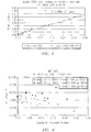
- Figure 12 shows a diagrammatic graph of differential pressure versus liquid gas mass ratio.
- the graph includes diagrammatic plots of flow velocity for wet gas flows of 50 ft/sec, 70 ft/sec, and 90 ft/sec.
- the three plots illustrate the sensitivity of the differential pressure to the LGMR parameter and therefore the wetness of the flow, as well as the influence of flow velocity.
- Figure 13 shows a diagrammatic graph of the ratio of differential pressure of a wet gas flow over differential pressure of a dry gas flow (DR wet / DP dry ) versus LGMR.
- the graph includes three plots of different flow velocities or Froude Numbers, where the uppermost plot represents the highest flow velocity and Froude number.
- the plots coincide at the DR wet / DP dry value of 1 where the gas flow is completely dry.
- the plots diverge as a function of the wetness of the flow.
- the above-described embodiment utilizing a flowmeter 402 and pressure sensors 404,406 can be used to create an empirical model to determine the wetness of a gas flow, and / or can be used to create an optimized analytical model for determining the same.
- the empirical model can be developed from data collected from a given piping system, where pressure loss data as a function of wetness can be determined for sets of constant flow pressure and velocity.
- the wetness sensitivity can be described graphically (e.g., slope and offset) or in tables.
- Figure 14 illustrates a graph of a parametric model of a linear pressure drop as a function of wetness, except for an initial onset of wetness for an LGMR of ⁇ ⁇ 0.05.
- the empirical model may require in-field calibration for the particular piping system at hand.
- V SONAR flow velocity
- DP/DX DP/DX
- initial values of flow velocity (V SONAR ) and DP (DP/DX) are input into an analytical model such as that described above, for the purpose of generating analytically determined liquid and gas flow rates.
- the initial values of V SONAR and DP/DX are then compared to the model generated V SONAR and DP/DX. If the delta between the compared values is great enough, the input V SONAR and DP/DX are updated and the process repeated. Once the values are within a predetermined range, the analytical model produces the optimized liquid and gas flow rates.
- Figure 15 illustrates a flow chart of an analytical optimization embodiment.
- the method of the invention may be embodied in the form of a computer or controller implemented processes.
- the invention may also be embodied in the form of computer program code containing instructions embodied in tangible media, such as floppy diskettes, CD-ROMs, hard drives, and/or any other computer-readable medium, wherein when the computer program code is loaded into and executed by a computer or controller, the computer or controller becomes an apparatus for practicing the invention.
- the invention can also be embodied in the form of computer program code, for example, whether stored in a storage medium, loaded into and/or executed by a computer or controller, or transmitted over some transmission medium, such as over electrical wiring or cabling, through fiber optics, or via electromagnetic radiation, wherein when the computer program code is loaded into and executed by a computer or a controller, the computer or controller becomes an apparatus for practicing the invention.
- computer program code segments may configure the microprocessor to create specific logic circuits.
Landscapes
- Physics & Mathematics (AREA)
- Fluid Mechanics (AREA)
- General Physics & Mathematics (AREA)
- Electromagnetism (AREA)
- Acoustics & Sound (AREA)
- Measuring Volume Flow (AREA)
Claims (15)
- Vorrichtung (400) zum Messen der Feuchtigkeit einer Gasströmung in einer Leitung (124), wobei die Vorrichtung (400) aufweist:einen ersten Drucksensor (404), der betriebswirksam ist, den Druck der Gasströmung in der Leitung (124) in einer ersten Position zu erfassen;einen zweiten Drucksensor (406), der betriebswirksam ist, den Druck der Gasströmung in der Leitung (124) in einer zweiten Position zu erfassen, wobei der erste und der zweite Drucksensor (404, 406) zusammen mindestens einen Teil eines Durchflussmessers bilden;einen sonarbasierten Durchflussmesser (402), der dazu ausgelegt ist, eine Volumendurchflussrate der Gasströmung zu bestimmen; undeine Verarbeitungsvorrichtung (134) in Kommunikation mit dem ersten und dem zweiten Drucksensor (404, 406) und dem sonarbasierten Durchflussmesser (402), wobei die Verarbeitungsvorrichtung (134) dafür ausgebildet ist, eine Differenz in dem von dem ersten und dem zweiten Drucksensor (404, 406) erfassten Druck zu bestimmen und die Feuchtigkeit der Gasströmung unter Verwendung der Differenz des Drucks und der Volumendurchflussrate zu bestimmen,
dadurch gekennzeichnet das,die zweite Position sich mit ausreichendem Abstand stromabwärts der ersten Position befindet, so dass die Gasströmung einen Druckabfall erfährt, der auf Reibungsverluste und durch die Leitungsgeometrie bedingte Verluste zurückzuführen ist;
und dadurch, dassdie Differenz in dem erfassten Druck direkt mit einem Flüssigkeit-zu-Gasmasse-Verhältnis der Gasströmung korreliert. - Vorrichtung (400) nach Anspruch 1, wobei der sonarbasierte Durchflussmesser (402) eine Anordnung von mindestens drei dehnungsbasierten Sensoren (118) umfasst.
- Vorrichtung (400) nach Anspruch 1, wobei der sonarbasierte Durchflussmesser (402) einen ultraschall-sonarbasierten Durchflussmesser (402) umfasst.
- Vorrichtung (400) nach Anspruch 1, wobei der sonarbasierte Durchflussmesser (402) zwischen dem ersten und dem zweiten Drucksensor (404, 406) angeordnet ist.
- Vorrichtung (400) nach Anspruch 1, wobei der sonarbasierte Durchflussmesser (402) entweder stromaufwärts oder stromabwärts von dem ersten und dem zweiten Drucksensor (404, 406) angeordnet ist.
- Vorrichtung (400) nach Anspruch 1, wobei der Prozessor dafür ausgebildet ist, die Feuchtigkeit der Gasströmung unter Verwendung empirischer Daten zu bestimmen.
- Vorrichtung (400) nach Anspruch 6, wobei die empirischen Daten aus einer Gasströmung entnommen werden, die in der Leitung (124) strömt.
- Vorrichtung (400) nach Anspruch 1, wobei der erste und der zweite Drucksensor (404, 406) empfindlich gegenüber der Feuchtigkeit der Gasströmung sind und der sonarbasierte Durchflussmesser (402) relativ dazu relativ unempfindlich gegenüber der Feuchtigkeit der Gasströmung ist.
- Vorrichtung (400) nach Anspruch 1, wobei die Leitung (124) ein Rohr ist.
- Verfahren zum Messen der Feuchtigkeit einer Gasströmung in einer Leitung (124), wobei das Verfahren aufweist:das Bereitstellen voneinem ersten Drucksensor (404), der betriebswirksam ist, ein Signal in Bezug auf den Druck der Gasströmung in der Leitung (124) in einer ersten Position zu erfassen;einem zweiten Drucksensor (406), der betriebswirksam ist, ein Signal in Bezug auf den Druck der Gasströmung in der Leitung (124) in einer zweiten Position zu erfassen, wobei der erste und der zweite Drucksensor (404, 406) zusammen mindestens einen Teil eines Durchflussmessers bilden, undeinem Durchflussmesser (402), der dazu ausgelegt ist, eine Volumendurchflussrate der Gasströmung zu bestimmen;das Bestimmen eines Differenzialdruckwertes, der eine Druckdifferenz in der Gasströmung zwischen der ersten und der zweiten Position unter Verwendung der Signale des ersten und des zweiten Drucksensors (404, 406) darstellt;das Bestimmen einer Volumendurchflussrate der Gasströmung als Reaktion auf einen Differenzialdruck in der Gasströmung unter Verwendung des Durchflussmessers (402); unddas Verarbeiten des Differenzialdruckwertes und der Volumendurchflussrate zur Bestimmung der Feuchtigkeit der Gasströmung;dadurch gekennzeichnet, dassdie zweite Position sich mit ausreichendem Abstand stromabwärts der ersten Position befindet, so dass die Gasströmung einen Druckabfall erfährt, der auf Reibungsverluste und durch die Leitungsgeometrie bedingte Verluste zurückzuführen ist;
und dadurch, dassdie Differenz in dem erfassten Druck direkt mit einem Flüssigkeit-zu-Gasmasse-Verhältnis der Gasströmung korreliert. - Verfahren nach Anspruch 10, wobei der Schritt des Bestimmens einer Volumendurchflussrate die Verwendung von Signalen von einer Anordnung von Sensoren (118) umfasst, die an unterschiedlichen axialen Stellen entlang einer Länge der Leitung (124) angeordnet sind, wobei die Signale auf unregelmäßigen Druck reagieren, der durch kohärente Strukturen verursacht wird, die mit der Gasströmung übertragen werden.
- Verfahren nach Anspruch 10, wobei der Schritt des Bestimmens einer Volumendurchflussrate das Bestimmen der Volumendurchflussrate unter Verwendung mindestens eines sonarbasierten Durchflussmessers (402) umfasst.
- Verfahren nach Anspruch 12, wobei der mindestens eine sonarbasierte Durchflussmesser (402) ein ultraschall-sonarbasierter Durchflussmesser ist.
- Verfahren nach Anspruch 10, wobei der Verarbeitungsschritt das Verarbeiten des Differenzialdruckwertes und der Volumendurchflussrate zur Bestimmung der Lockhardt Martinelli (LM)-Zahl umfasst, die gegeben ist durch

- Verfahren nach Anspruch 10, wobei der Prozessor die Feuchtigkeit der Gasströmung unter Verwendung empirischer Daten bestimmt, wobei die empirischen Daten vorzugsweise aus der Gasströmung erfasst werden, die in der Leitung (124) strömt.
Applications Claiming Priority (2)
| Application Number | Priority Date | Filing Date | Title |
|---|---|---|---|
| US11/972,228 US7603916B2 (en) | 2005-07-07 | 2008-01-10 | Wet gas metering using a differential pressure and a sonar based flow meter |
| PCT/US2009/030584 WO2009089438A1 (en) | 2008-01-10 | 2009-01-09 | Wet gas metering using a differential pressure and a sonar based flow meter |
Publications (2)
| Publication Number | Publication Date |
|---|---|
| EP2238415A1 EP2238415A1 (de) | 2010-10-13 |
| EP2238415B1 true EP2238415B1 (de) | 2018-10-03 |
Family
ID=40672553
Family Applications (1)
| Application Number | Title | Priority Date | Filing Date |
|---|---|---|---|
| EP09700436.0A Active EP2238415B1 (de) | 2008-01-10 | 2009-01-09 | Flüssiggasmessung unter verwendung eines differentialdruckbasierten durchflussmessers mit einem sonarbasierten durchflussmesser |
Country Status (6)
| Country | Link |
|---|---|
| US (1) | US7603916B2 (de) |
| EP (1) | EP2238415B1 (de) |
| AU (1) | AU2009204007B2 (de) |
| BR (1) | BRPI0906694A2 (de) |
| CA (1) | CA2711625C (de) |
| WO (1) | WO2009089438A1 (de) |
Families Citing this family (34)
| Publication number | Priority date | Publication date | Assignee | Title |
|---|---|---|---|---|
| US7962293B2 (en) * | 2005-03-10 | 2011-06-14 | Expro Meters, Inc. | Apparatus and method for providing a stratification metric of a multiphase fluid flowing within a pipe |
| CN102089673A (zh) * | 2008-05-09 | 2011-06-08 | 锡德拉企业服务公司 | 将基于声纳的vf/gvf计量应用于工业处理 |
| WO2010138595A1 (en) * | 2009-05-26 | 2010-12-02 | Expro Meters, Inc. | Method and apparatus for monitoring multiphase fluid flow |
| US10394207B2 (en) | 2009-06-12 | 2019-08-27 | CiDRA Corporate Service Inc. | Techniques for optimizing performance of cyclones |
| WO2015031308A2 (en) * | 2013-08-26 | 2015-03-05 | Cidra Corporate Services Inc. | Techniques for optimizing performance of cyclones |
| WO2011019823A1 (en) * | 2009-08-11 | 2011-02-17 | Cidra Corporate Services Inc. | Performance monitoring of individual hydrocyclones using sonar-based slurry flow measurement |
| US9068872B2 (en) | 2009-08-11 | 2015-06-30 | Expro Meters, Inc. | Method and apparatus for monitoring multiphase fluid flow |
| JP5477051B2 (ja) * | 2010-03-01 | 2014-04-23 | 株式会社デンソー | 超音波流量計 |
| WO2011159816A1 (en) | 2010-06-15 | 2011-12-22 | Expro Meters, Inc. | Minimally intrusive monitoring of a multiphase process flow using a tracer |
| US7966892B1 (en) * | 2010-08-09 | 2011-06-28 | Halilah Sami O | In line sampler separator |
| GB2483671B (en) * | 2010-09-15 | 2016-04-13 | Managed Pressure Operations | Drilling system |
| EP2649418A1 (de) | 2010-12-07 | 2013-10-16 | Expro Meters, Inc. | Verfahren zur in-situ-kalibrierung eines differenzialdruck- und sonardurchflussmesssystems mit trockengasbedingungen |
| EP3974784B1 (de) * | 2011-10-28 | 2026-05-06 | DeLaval Holding AB | Mehrphasen-flussmessung |
| US9719821B2 (en) | 2011-10-28 | 2017-08-01 | Delaval Holding Ab | Multiphase flow measurement |
| US8869627B2 (en) | 2012-07-09 | 2014-10-28 | King Fahd University Of Petroleum And Minerals | Multi-phase flow metering system |
| US9383476B2 (en) * | 2012-07-09 | 2016-07-05 | Weatherford Technology Holdings, Llc | In-well full-bore multiphase flowmeter for horizontal wellbores |
| EP2909439B1 (de) | 2012-10-16 | 2017-12-06 | Expro Meters, Inc. | Systeme und verfahren zur verwaltung von kohlenwasserstoffmaterialproduzierenden bohrplätzen mit aufklemmbaren durchflussmessvorrichtungen |
| RU2535515C2 (ru) * | 2012-11-19 | 2014-12-10 | Эндрю Уильям Джэмисон | Способ определения расхода влажного газа |
| WO2014181076A1 (en) * | 2013-05-04 | 2014-11-13 | Richard Steven | Flow metering |
| US9410422B2 (en) | 2013-09-13 | 2016-08-09 | Chevron U.S.A. Inc. | Alternative gauging system for production well testing and related methods |
| NO344565B1 (no) * | 2013-10-01 | 2020-02-03 | Fmc Kongsberg Subsea As | Fremgangsmåte og apparat for måling av individuelle komponenter i et flerfasefluid |
| US10704939B2 (en) * | 2015-07-28 | 2020-07-07 | Expro Meters, Inc. | Methodology and apparatus for distinguishing single phase fluid flows from multiphase fluid flows using a flow meter |
| US10384161B2 (en) * | 2015-09-08 | 2019-08-20 | Saudi Arabian Oil Company | Systems and methods for accurate measurement of gas from wet gas wells |
| DE102017113453A1 (de) * | 2017-06-19 | 2018-12-20 | Krohne Ag | Durchflusssensor, Verfahren und Durchflussmessgerät zur Bestimmung von Geschwindigkeiten von Phasen eines mehrphasigen Mediums |
| CN107782399B (zh) * | 2017-11-22 | 2020-01-07 | 连云港新奥燃气有限公司 | 具备自主防盗功能的天然气气体计量装置 |
| DE102018110456A1 (de) | 2018-05-02 | 2019-11-07 | Endress + Hauser Flowtec Ag | Meßsystem sowie Verfahren zum Messen einer Meßgröße eines strömenden Fluids |
| US11150154B2 (en) * | 2018-06-08 | 2021-10-19 | Orbis Intelligent Systems, Inc. | Pipe sensors |
| US11698314B2 (en) | 2018-06-08 | 2023-07-11 | Orbis Intelligent Systems, Inc. | Detection device for a fluid conduit or fluid dispensing device |
| US12590824B2 (en) | 2018-06-08 | 2026-03-31 | Orbis Intelligent Systems, Inc. | Monitoring sites of a fluid delivery infrastructure |
| US11733115B2 (en) | 2018-06-08 | 2023-08-22 | Orbis Intelligent Systems, Inc. | Detection devices for determining one or more pipe conditions via at least one acoustic sensor and including connection features to connect with an insert |
| US12152954B2 (en) | 2018-06-08 | 2024-11-26 | Orbis Intelligent Systems, Inc. | Detection device for a fluid conduit or fluid dispensing device |
| WO2022093389A1 (en) | 2020-10-27 | 2022-05-05 | Expro Meters, Inc. | Method and apparatus for measuring wet gas utilizing an augmented coriolis flow meter |
| US11668618B2 (en) * | 2021-09-27 | 2023-06-06 | Flowserve Pte. Ltd. | Apparatus for measuring the pressure and flow rate of a high temperature corrosive liquid |
| US12013273B2 (en) | 2022-02-23 | 2024-06-18 | Saudi Arabian Oil Company | Drilling mud flow metering system and method |
Family Cites Families (91)
| Publication number | Priority date | Publication date | Assignee | Title |
|---|---|---|---|---|
| US2874568A (en) | 1955-12-07 | 1959-02-24 | Gulton Ind Inc | Ultrasonic flowmeter |
| GB1208121A (en) | 1967-02-08 | 1970-10-07 | British Oxygen Co Ltd | Apparatus for metering a mixture of gas and liquid |
| GB1528917A (en) | 1974-12-11 | 1978-10-18 | Detectronic Ltd | Method and apparatus for monitoring the flow of liquid and the like |
| US4004461A (en) | 1975-11-07 | 1977-01-25 | Panametrics, Inc. | Ultrasonic measuring system with isolation means |
| US4080837A (en) | 1976-12-03 | 1978-03-28 | Continental Oil Company | Sonic measurement of flow rate and water content of oil-water streams |
| DE2856032A1 (de) | 1978-01-03 | 1979-07-12 | Coulthard John | Vorrichtung und verfahren zum messen der geschwindigkeit einer relativbewegung zwischen einem ersten koerper und einem zweiten koerper bzw. einem stroemungsmittel |
| US4195517A (en) | 1978-12-18 | 1980-04-01 | The Foxboro Company | Ultrasonic flowmeter |
| US4445389A (en) | 1981-09-10 | 1984-05-01 | The United States Of America As Represented By The Secretary Of Commerce | Long wavelength acoustic flowmeter |
| US4576043A (en) | 1984-05-17 | 1986-03-18 | Chevron Research Company | Methods for metering two-phase flow |
| NO166379C (no) | 1987-12-18 | 1991-07-10 | Sensorteknikk As | Fremgangsmaate for registrering av flerfase stroemninger gjennom et transportsystem. |
| US4896540A (en) | 1988-04-08 | 1990-01-30 | Parthasarathy Shakkottai | Aeroacoustic flowmeter |
| US5115670A (en) | 1990-03-09 | 1992-05-26 | Chevron Research & Technology Company | Measurement of fluid properties of two-phase fluids using an ultrasonic meter |
| US5040415A (en) | 1990-06-15 | 1991-08-20 | Rockwell International Corporation | Nonintrusive flow sensing system |
| GB2253907B (en) | 1991-03-21 | 1995-05-24 | Halliburton Logging Services | Device for sensing fluid behaviour |
| NO174643C (no) | 1992-01-13 | 1994-06-08 | Jon Steinar Gudmundsson | Apparat og framgangsmåte for bestemmelse av strömningshastighet og gass/væske-forhold i flerefase-strömmer |
| US5461930A (en) | 1992-03-17 | 1995-10-31 | Agar Corporation Inc. | Apparatus and method for measuring two-or three-phase fluid flow utilizing one or more momentum flow meters and a volumetric flow meter |
| US5285675A (en) | 1992-06-05 | 1994-02-15 | University Of Florida Research Foundation, Inc. | Acoustic fluid flow monitoring |
| US5398542A (en) | 1992-10-16 | 1995-03-21 | Nkk Corporation | Method for determining direction of travel of a wave front and apparatus therefor |
| GB2282931B (en) | 1993-10-16 | 1997-11-12 | Atomic Energy Authority Uk | Flexible transducer array support |
| FI94909C (fi) | 1994-04-19 | 1995-11-10 | Valtion Teknillinen | Akustinen virtausmittausmenetelmä ja sitä soveltava laite |
| FR2720498B1 (fr) | 1994-05-27 | 1996-08-09 | Schlumberger Services Petrol | Débitmètre multiphasique. |
| US5589642A (en) | 1994-09-13 | 1996-12-31 | Agar Corporation Inc. | High void fraction multi-phase fluid flow meter |
| US5741980A (en) | 1994-11-02 | 1998-04-21 | Foster-Miller, Inc. | Flow analysis system and method |
| US5524475A (en) | 1994-11-10 | 1996-06-11 | Atlantic Richfield Company | Measuring vibration of a fluid stream to determine gas fraction |
| JP3216769B2 (ja) | 1995-03-20 | 2001-10-09 | 富士電機株式会社 | クランプオン型超音波流量計における温度圧力補償方法 |
| FR2740215B1 (fr) | 1995-10-19 | 1997-11-21 | Inst Francais Du Petrole | Methode et dispositif pour mesurer un parametre d'un fluide de densite variable |
| US6151958A (en) | 1996-03-11 | 2000-11-28 | Daniel Industries, Inc. | Ultrasonic fraction and flow rate apparatus and method |
| US5835884A (en) | 1996-10-04 | 1998-11-10 | Brown; Alvin E. | Method of determining a characteristic of a fluid |
| DE19722274A1 (de) | 1997-05-28 | 1998-12-03 | Degussa | Verfahren zur Messung von Dichte und Massenstrom |
| US5948959A (en) | 1997-05-29 | 1999-09-07 | The United States Of America As Represented By The Secretary Of The Navy | Calibration of the normal pressure transfer function of a compliant fluid-filled cylinder |
| CA2239202A1 (en) | 1998-05-29 | 1999-11-29 | Travis H. Wolfe | Method and apparatus for determining the water content of an oil stream |
| GB9813509D0 (en) | 1998-06-24 | 1998-08-19 | British Gas Plc | Measuring the speed of sound of a gas |
| EP1090274B1 (de) | 1998-06-26 | 2017-03-15 | Weatherford Technology Holdings, LLC | Flüssigkeitsparametermessung unter verwendung von akustischem druck |
| US6450037B1 (en) | 1998-06-26 | 2002-09-17 | Cidra Corporation | Non-intrusive fiber optic pressure sensor for measuring unsteady pressures within a pipe |
| US6354147B1 (en) | 1998-06-26 | 2002-03-12 | Cidra Corporation | Fluid parameter measurement in pipes using acoustic pressures |
| WO2000000799A1 (en) | 1998-06-26 | 2000-01-06 | Cidra Corporation | Non-intrusive fiber optic pressure sensor for measuring unsteady pressures within a pipe |
| US6397683B1 (en) | 1998-07-22 | 2002-06-04 | Flowtec Ag | Clamp-on ultrasonic flowmeter |
| US6463813B1 (en) | 1999-06-25 | 2002-10-15 | Weatherford/Lamb, Inc. | Displacement based pressure sensor measuring unsteady pressure in a pipe |
| AU776582B2 (en) | 1999-07-02 | 2004-09-16 | Weatherford Technology Holdings, Llc | Flow rate measurement using unsteady pressures |
| US6691584B2 (en) | 1999-07-02 | 2004-02-17 | Weatherford/Lamb, Inc. | Flow rate measurement using unsteady pressures |
| US6536291B1 (en) | 1999-07-02 | 2003-03-25 | Weatherford/Lamb, Inc. | Optical flow rate measurement using unsteady pressures |
| US6813962B2 (en) | 2000-03-07 | 2004-11-09 | Weatherford/Lamb, Inc. | Distributed sound speed measurements for multiphase flow measurement |
| US6378357B1 (en) | 2000-03-14 | 2002-04-30 | Halliburton Energy Services, Inc. | Method of fluid rheology characterization and apparatus therefor |
| US6558036B2 (en) | 2000-11-29 | 2003-05-06 | Weatherford/Lamb, Inc. | Non-intrusive temperature sensor for measuring internal temperature of fluids within pipes |
| US6782150B2 (en) | 2000-11-29 | 2004-08-24 | Weatherford/Lamb, Inc. | Apparatus for sensing fluid in a pipe |
| US6587798B2 (en) | 2000-12-04 | 2003-07-01 | Weatherford/Lamb, Inc. | Method and system for determining the speed of sound in a fluid within a conduit |
| US6609069B2 (en) | 2000-12-04 | 2003-08-19 | Weatherford/Lamb, Inc. | Method and apparatus for determining the flow velocity of a fluid within a pipe |
| US6898541B2 (en) | 2000-12-04 | 2005-05-24 | Weatherford/Lamb, Inc. | Method and apparatus for determining component flow rates for a multiphase flow |
| JP2003075219A (ja) | 2001-09-06 | 2003-03-12 | Kazumasa Onishi | クランプオン型超音波流量計 |
| DE10147189A1 (de) * | 2001-09-25 | 2003-04-24 | Bosch Gmbh Robert | Verfahren zum Betreiben eines Kraftstoffversorgungssystems für einen Verbrennungsmotor eines Kraftfahrzeugs |
| US7059172B2 (en) | 2001-11-07 | 2006-06-13 | Weatherford/Lamb, Inc. | Phase flow measurement in pipes using a density meter |
| US6698297B2 (en) | 2002-06-28 | 2004-03-02 | Weatherford/Lamb, Inc. | Venturi augmented flow meter |
| US6971259B2 (en) | 2001-11-07 | 2005-12-06 | Weatherford/Lamb, Inc. | Fluid density measurement in pipes using acoustic pressures |
| US7359803B2 (en) | 2002-01-23 | 2008-04-15 | Cidra Corporation | Apparatus and method for measuring parameters of a mixture having solid particles suspended in a fluid flowing in a pipe |
| US7328624B2 (en) | 2002-01-23 | 2008-02-12 | Cidra Corporation | Probe for measuring parameters of a flowing fluid and/or multiphase mixture |
| US7275421B2 (en) | 2002-01-23 | 2007-10-02 | Cidra Corporation | Apparatus and method for measuring parameters of a mixture having solid particles suspended in a fluid flowing in a pipe |
| US7032432B2 (en) | 2002-01-23 | 2006-04-25 | Cidra Corporation | Apparatus and method for measuring parameters of a mixture having liquid droplets suspended in a vapor flowing in a pipe |
| AU2003255235A1 (en) | 2002-08-08 | 2004-02-25 | Cidra Corporation | Apparatus and method for measuring multi-phase flows in pulp and paper industry applications |
| EP1567833A2 (de) | 2002-11-12 | 2005-08-31 | CiDra Corporation | Apparat mit einer reihe von piezoelektrischen film sensoren zur messung von parametern eines prozessflusses in einem rohr |
| US7165464B2 (en) | 2002-11-15 | 2007-01-23 | Cidra Corporation | Apparatus and method for providing a flow measurement compensated for entrained gas |
| WO2004048906A2 (en) | 2002-11-22 | 2004-06-10 | Cidra Corporation | Method for calibrating a flow meter having an array of sensors |
| US7096719B2 (en) | 2003-01-13 | 2006-08-29 | Cidra Corporation | Apparatus for measuring parameters of a flowing multiphase mixture |
| CA2513248C (en) | 2003-01-13 | 2013-01-08 | Cidra Corporation | Apparatus and method using an array of ultrasonic sensors for determining the velocity of a fluid within a pipe |
| WO2004065912A2 (en) | 2003-01-21 | 2004-08-05 | Cidra Corporation | Apparatus and method for measuring unsteady pressures within a large diameter pipe |
| US20060048583A1 (en) | 2004-08-16 | 2006-03-09 | Gysling Daniel L | Total gas meter using speed of sound and velocity measurements |
| ATE549603T1 (de) | 2003-01-21 | 2012-03-15 | Cidra Corporate Services Inc | Messung eingeschlossener und aufgelöster gase in prozessflussleitungen |
| US6945095B2 (en) | 2003-01-21 | 2005-09-20 | Weatherford/Lamb, Inc. | Non-intrusive multiphase flow meter |
| DE602004017571D1 (de) | 2003-01-21 | 2008-12-18 | Expro Meters Inc | Vorrichtung und verfahren zur messung der gasvolumenfraktion eines in einem rohr strömenden fluids |
| US7146864B2 (en) | 2003-03-04 | 2006-12-12 | Cidra Corporation | Apparatus having a multi-band sensor assembly for measuring a parameter of a fluid flow flowing within a pipe |
| US6837098B2 (en) | 2003-03-19 | 2005-01-04 | Weatherford/Lamb, Inc. | Sand monitoring within wells using acoustic arrays |
| WO2004109239A2 (en) | 2003-06-05 | 2004-12-16 | Cidra Corporation | Apparatus for measuring velocity and flow rate of a fluid having a non-negligible axial mach number using an array of sensors |
| WO2005003695A1 (en) | 2003-06-24 | 2005-01-13 | Cidra Corporation | Characterizing unsteady pressures in pipes using optical measurement devices |
| US7197938B2 (en) | 2003-06-24 | 2007-04-03 | Cidra Corporation | Contact-based transducers for characterizing unsteady pressures in pipes |
| WO2005010469A2 (en) | 2003-07-15 | 2005-02-03 | Cidra Corporation | A dual function flow measurement apparatus having an array of sensors |
| CA2532592C (en) | 2003-07-15 | 2013-11-26 | Cidra Corporation | An apparatus and method for compensating a coriolis meter |
| US7134320B2 (en) | 2003-07-15 | 2006-11-14 | Cidra Corporation | Apparatus and method for providing a density measurement augmented for entrained gas |
| WO2005010468A2 (en) | 2003-07-15 | 2005-02-03 | Cidra Corporation | A configurable multi-function flow measurement apparatus having an array of sensors |
| RU2324171C2 (ru) | 2003-07-18 | 2008-05-10 | Роузмаунт Инк. | Диагностика процесса |
| WO2005012843A2 (en) | 2003-08-01 | 2005-02-10 | Cidra Corporation | Method and apparatus for measuring parameters of a fluid flowing within a pipe using a configurable array of sensors |
| US7110893B2 (en) | 2003-10-09 | 2006-09-19 | Cidra Corporation | Method and apparatus for measuring a parameter of a fluid flowing within a pipe using an array of sensors |
| US7237440B2 (en) | 2003-10-10 | 2007-07-03 | Cidra Corporation | Flow measurement apparatus having strain-based sensors and ultrasonic sensors |
| WO2005040732A1 (en) | 2003-10-27 | 2005-05-06 | Elster-Instromet Ultrasonics B.V. | Wet gas measurement apparatus and method |
| US7171315B2 (en) | 2003-11-25 | 2007-01-30 | Cidra Corporation | Method and apparatus for measuring a parameter of a fluid flowing within a pipe using sub-array processing |
| US7152003B2 (en) | 2003-12-11 | 2006-12-19 | Cidra Corporation | Method and apparatus for determining a quality metric of a measurement of a fluid parameter |
| BRPI0508637B1 (pt) | 2004-03-10 | 2017-10-10 | Cidra Corporation | Method and apparatus for measuring parameters of a stratified flow |
| WO2005116637A2 (en) | 2004-05-17 | 2005-12-08 | Cidra Corporation | Apparatus and method for measuring the composition of a mixture |
| US7866211B2 (en) | 2004-07-16 | 2011-01-11 | Rosemount Inc. | Fouling and corrosion detector for process control industries |
| US7284387B2 (en) * | 2004-09-16 | 2007-10-23 | Hess Spencer W | Diesel fuel heated dessicant reactivation with internal heat bypass |
| WO2006112878A2 (en) | 2004-09-16 | 2006-10-26 | Cidra Corporation | Apparatus and method for providing a fluid cut measurement of a multi-liquid mixture compensated for entrained gas |
| BRPI0612768A2 (pt) * | 2005-07-07 | 2010-11-30 | Cidra Corp | sistema de medição de fluxo multifásico que tem um separador de fluìdo |
| EP1899686B1 (de) * | 2005-07-07 | 2011-09-28 | CiDra Corporation | Feuchtgasmessung unter verwendung eines differentialdruckbasierten durchflussmeters mit einem sonarbasierten durchflussmeter |
-
2008
- 2008-01-10 US US11/972,228 patent/US7603916B2/en active Active
-
2009
- 2009-01-09 AU AU2009204007A patent/AU2009204007B2/en not_active Ceased
- 2009-01-09 BR BRPI0906694-2A patent/BRPI0906694A2/pt not_active Application Discontinuation
- 2009-01-09 EP EP09700436.0A patent/EP2238415B1/de active Active
- 2009-01-09 WO PCT/US2009/030584 patent/WO2009089438A1/en not_active Ceased
- 2009-01-09 CA CA2711625A patent/CA2711625C/en active Active
Non-Patent Citations (1)
| Title |
|---|
| None * |
Also Published As
| Publication number | Publication date |
|---|---|
| US20080236298A1 (en) | 2008-10-02 |
| CA2711625C (en) | 2019-09-10 |
| CA2711625A1 (en) | 2009-07-16 |
| WO2009089438A1 (en) | 2009-07-16 |
| BRPI0906694A2 (pt) | 2015-06-30 |
| AU2009204007B2 (en) | 2014-03-20 |
| AU2009204007A1 (en) | 2009-07-16 |
| EP2238415A1 (de) | 2010-10-13 |
| US7603916B2 (en) | 2009-10-20 |
Similar Documents
| Publication | Publication Date | Title |
|---|---|---|
| EP2238415B1 (de) | Flüssiggasmessung unter verwendung eines differentialdruckbasierten durchflussmessers mit einem sonarbasierten durchflussmesser | |
| EP1899686B1 (de) | Feuchtgasmessung unter verwendung eines differentialdruckbasierten durchflussmeters mit einem sonarbasierten durchflussmeter | |
| EP1899687B1 (de) | Mehrphasiges durchflussmessungssystem mit flüssigkeitsabscheider | |
| US7454981B2 (en) | Apparatus and method for determining a parameter in a wet gas flow | |
| US7152003B2 (en) | Method and apparatus for determining a quality metric of a measurement of a fluid parameter | |
| US7171315B2 (en) | Method and apparatus for measuring a parameter of a fluid flowing within a pipe using sub-array processing | |
| US7197942B2 (en) | Apparatus for measuring velocity and flow rate of a fluid having a non-negligible axial mach number using an array of sensors | |
| CA2719772C (en) | A system and method for providing a compositional measurement of a mixture having entrained gas | |
| US7437946B2 (en) | Apparatus and method for measuring a parameter of a multiphase flow | |
| US7380438B2 (en) | Apparatus and method for providing a fluid cut measurement of a multi-liquid mixture compensated for entrained gas |
Legal Events
| Date | Code | Title | Description |
|---|---|---|---|
| PUAI | Public reference made under article 153(3) epc to a published international application that has entered the european phase |
Free format text: ORIGINAL CODE: 0009012 |
|
| 17P | Request for examination filed |
Effective date: 20100802 |
|
| AK | Designated contracting states |
Kind code of ref document: A1 Designated state(s): AT BE BG CH CY CZ DE DK EE ES FI FR GB GR HR HU IE IS IT LI LT LU LV MC MK MT NL NO PL PT RO SE SI SK TR |
|
| AX | Request for extension of the european patent |
Extension state: AL BA RS |
|
| DAX | Request for extension of the european patent (deleted) | ||
| 17Q | First examination report despatched |
Effective date: 20160502 |
|
| GRAP | Despatch of communication of intention to grant a patent |
Free format text: ORIGINAL CODE: EPIDOSNIGR1 |
|
| STAA | Information on the status of an ep patent application or granted ep patent |
Free format text: STATUS: GRANT OF PATENT IS INTENDED |
|
| INTG | Intention to grant announced |
Effective date: 20180418 |
|
| GRAS | Grant fee paid |
Free format text: ORIGINAL CODE: EPIDOSNIGR3 |
|
| GRAA | (expected) grant |
Free format text: ORIGINAL CODE: 0009210 |
|
| STAA | Information on the status of an ep patent application or granted ep patent |
Free format text: STATUS: THE PATENT HAS BEEN GRANTED |
|
| AK | Designated contracting states |
Kind code of ref document: B1 Designated state(s): AT BE BG CH CY CZ DE DK EE ES FI FR GB GR HR HU IE IS IT LI LT LU LV MC MK MT NL NO PL PT RO SE SI SK TR |
|
| REG | Reference to a national code |
Ref country code: GB Ref legal event code: FG4D |
|
| REG | Reference to a national code |
Ref country code: CH Ref legal event code: EP Ref country code: AT Ref legal event code: REF Ref document number: 1049105 Country of ref document: AT Kind code of ref document: T Effective date: 20181015 |
|
| REG | Reference to a national code |
Ref country code: DE Ref legal event code: R096 Ref document number: 602009054843 Country of ref document: DE |
|
| REG | Reference to a national code |
Ref country code: IE Ref legal event code: FG4D |
|
| REG | Reference to a national code |
Ref country code: NL Ref legal event code: MP Effective date: 20181003 |
|
| REG | Reference to a national code |
Ref country code: LT Ref legal event code: MG4D Ref country code: NO Ref legal event code: T2 Effective date: 20181003 |
|
| REG | Reference to a national code |
Ref country code: AT Ref legal event code: MK05 Ref document number: 1049105 Country of ref document: AT Kind code of ref document: T Effective date: 20181003 |
|
| PG25 | Lapsed in a contracting state [announced via postgrant information from national office to epo] |
Ref country code: NL Free format text: LAPSE BECAUSE OF FAILURE TO SUBMIT A TRANSLATION OF THE DESCRIPTION OR TO PAY THE FEE WITHIN THE PRESCRIBED TIME-LIMIT Effective date: 20181003 |
|
| PG25 | Lapsed in a contracting state [announced via postgrant information from national office to epo] |
Ref country code: FI Free format text: LAPSE BECAUSE OF FAILURE TO SUBMIT A TRANSLATION OF THE DESCRIPTION OR TO PAY THE FEE WITHIN THE PRESCRIBED TIME-LIMIT Effective date: 20181003 Ref country code: IS Free format text: LAPSE BECAUSE OF FAILURE TO SUBMIT A TRANSLATION OF THE DESCRIPTION OR TO PAY THE FEE WITHIN THE PRESCRIBED TIME-LIMIT Effective date: 20190203 Ref country code: BG Free format text: LAPSE BECAUSE OF FAILURE TO SUBMIT A TRANSLATION OF THE DESCRIPTION OR TO PAY THE FEE WITHIN THE PRESCRIBED TIME-LIMIT Effective date: 20190103 Ref country code: LT Free format text: LAPSE BECAUSE OF FAILURE TO SUBMIT A TRANSLATION OF THE DESCRIPTION OR TO PAY THE FEE WITHIN THE PRESCRIBED TIME-LIMIT Effective date: 20181003 Ref country code: CZ Free format text: LAPSE BECAUSE OF FAILURE TO SUBMIT A TRANSLATION OF THE DESCRIPTION OR TO PAY THE FEE WITHIN THE PRESCRIBED TIME-LIMIT Effective date: 20181003 Ref country code: AT Free format text: LAPSE BECAUSE OF FAILURE TO SUBMIT A TRANSLATION OF THE DESCRIPTION OR TO PAY THE FEE WITHIN THE PRESCRIBED TIME-LIMIT Effective date: 20181003 Ref country code: ES Free format text: LAPSE BECAUSE OF FAILURE TO SUBMIT A TRANSLATION OF THE DESCRIPTION OR TO PAY THE FEE WITHIN THE PRESCRIBED TIME-LIMIT Effective date: 20181003 Ref country code: LV Free format text: LAPSE BECAUSE OF FAILURE TO SUBMIT A TRANSLATION OF THE DESCRIPTION OR TO PAY THE FEE WITHIN THE PRESCRIBED TIME-LIMIT Effective date: 20181003 Ref country code: PL Free format text: LAPSE BECAUSE OF FAILURE TO SUBMIT A TRANSLATION OF THE DESCRIPTION OR TO PAY THE FEE WITHIN THE PRESCRIBED TIME-LIMIT Effective date: 20181003 Ref country code: HR Free format text: LAPSE BECAUSE OF FAILURE TO SUBMIT A TRANSLATION OF THE DESCRIPTION OR TO PAY THE FEE WITHIN THE PRESCRIBED TIME-LIMIT Effective date: 20181003 |
|
| PG25 | Lapsed in a contracting state [announced via postgrant information from national office to epo] |
Ref country code: PT Free format text: LAPSE BECAUSE OF FAILURE TO SUBMIT A TRANSLATION OF THE DESCRIPTION OR TO PAY THE FEE WITHIN THE PRESCRIBED TIME-LIMIT Effective date: 20190203 Ref country code: SE Free format text: LAPSE BECAUSE OF FAILURE TO SUBMIT A TRANSLATION OF THE DESCRIPTION OR TO PAY THE FEE WITHIN THE PRESCRIBED TIME-LIMIT Effective date: 20181003 Ref country code: GR Free format text: LAPSE BECAUSE OF FAILURE TO SUBMIT A TRANSLATION OF THE DESCRIPTION OR TO PAY THE FEE WITHIN THE PRESCRIBED TIME-LIMIT Effective date: 20190104 |
|
| REG | Reference to a national code |
Ref country code: DE Ref legal event code: R097 Ref document number: 602009054843 Country of ref document: DE |
|
| PG25 | Lapsed in a contracting state [announced via postgrant information from national office to epo] |
Ref country code: DK Free format text: LAPSE BECAUSE OF FAILURE TO SUBMIT A TRANSLATION OF THE DESCRIPTION OR TO PAY THE FEE WITHIN THE PRESCRIBED TIME-LIMIT Effective date: 20181003 Ref country code: IT Free format text: LAPSE BECAUSE OF FAILURE TO SUBMIT A TRANSLATION OF THE DESCRIPTION OR TO PAY THE FEE WITHIN THE PRESCRIBED TIME-LIMIT Effective date: 20181003 |
|
| REG | Reference to a national code |
Ref country code: DE Ref legal event code: R119 Ref document number: 602009054843 Country of ref document: DE |
|
| PLBE | No opposition filed within time limit |
Free format text: ORIGINAL CODE: 0009261 |
|
| STAA | Information on the status of an ep patent application or granted ep patent |
Free format text: STATUS: NO OPPOSITION FILED WITHIN TIME LIMIT |
|
| PG25 | Lapsed in a contracting state [announced via postgrant information from national office to epo] |
Ref country code: EE Free format text: LAPSE BECAUSE OF FAILURE TO SUBMIT A TRANSLATION OF THE DESCRIPTION OR TO PAY THE FEE WITHIN THE PRESCRIBED TIME-LIMIT Effective date: 20181003 Ref country code: RO Free format text: LAPSE BECAUSE OF FAILURE TO SUBMIT A TRANSLATION OF THE DESCRIPTION OR TO PAY THE FEE WITHIN THE PRESCRIBED TIME-LIMIT Effective date: 20181003 Ref country code: SK Free format text: LAPSE BECAUSE OF FAILURE TO SUBMIT A TRANSLATION OF THE DESCRIPTION OR TO PAY THE FEE WITHIN THE PRESCRIBED TIME-LIMIT Effective date: 20181003 Ref country code: MC Free format text: LAPSE BECAUSE OF FAILURE TO SUBMIT A TRANSLATION OF THE DESCRIPTION OR TO PAY THE FEE WITHIN THE PRESCRIBED TIME-LIMIT Effective date: 20181003 |
|
| REG | Reference to a national code |
Ref country code: CH Ref legal event code: PL |
|
| 26N | No opposition filed |
Effective date: 20190704 |
|
| PG25 | Lapsed in a contracting state [announced via postgrant information from national office to epo] |
Ref country code: LU Free format text: LAPSE BECAUSE OF NON-PAYMENT OF DUE FEES Effective date: 20190109 |
|
| REG | Reference to a national code |
Ref country code: BE Ref legal event code: MM Effective date: 20190131 |
|
| REG | Reference to a national code |
Ref country code: IE Ref legal event code: MM4A |
|
| PG25 | Lapsed in a contracting state [announced via postgrant information from national office to epo] |
Ref country code: FR Free format text: LAPSE BECAUSE OF NON-PAYMENT OF DUE FEES Effective date: 20190131 Ref country code: DE Free format text: LAPSE BECAUSE OF NON-PAYMENT OF DUE FEES Effective date: 20190801 Ref country code: SI Free format text: LAPSE BECAUSE OF FAILURE TO SUBMIT A TRANSLATION OF THE DESCRIPTION OR TO PAY THE FEE WITHIN THE PRESCRIBED TIME-LIMIT Effective date: 20181003 |
|
| PG25 | Lapsed in a contracting state [announced via postgrant information from national office to epo] |
Ref country code: BE Free format text: LAPSE BECAUSE OF NON-PAYMENT OF DUE FEES Effective date: 20190131 |
|
| PG25 | Lapsed in a contracting state [announced via postgrant information from national office to epo] |
Ref country code: LI Free format text: LAPSE BECAUSE OF NON-PAYMENT OF DUE FEES Effective date: 20190131 Ref country code: CH Free format text: LAPSE BECAUSE OF NON-PAYMENT OF DUE FEES Effective date: 20190131 |
|
| PG25 | Lapsed in a contracting state [announced via postgrant information from national office to epo] |
Ref country code: IE Free format text: LAPSE BECAUSE OF NON-PAYMENT OF DUE FEES Effective date: 20190109 |
|
| PG25 | Lapsed in a contracting state [announced via postgrant information from national office to epo] |
Ref country code: TR Free format text: LAPSE BECAUSE OF FAILURE TO SUBMIT A TRANSLATION OF THE DESCRIPTION OR TO PAY THE FEE WITHIN THE PRESCRIBED TIME-LIMIT Effective date: 20181003 |
|
| PG25 | Lapsed in a contracting state [announced via postgrant information from national office to epo] |
Ref country code: MT Free format text: LAPSE BECAUSE OF NON-PAYMENT OF DUE FEES Effective date: 20190109 |
|
| PG25 | Lapsed in a contracting state [announced via postgrant information from national office to epo] |
Ref country code: CY Free format text: LAPSE BECAUSE OF FAILURE TO SUBMIT A TRANSLATION OF THE DESCRIPTION OR TO PAY THE FEE WITHIN THE PRESCRIBED TIME-LIMIT Effective date: 20181003 |
|
| PG25 | Lapsed in a contracting state [announced via postgrant information from national office to epo] |
Ref country code: HU Free format text: LAPSE BECAUSE OF FAILURE TO SUBMIT A TRANSLATION OF THE DESCRIPTION OR TO PAY THE FEE WITHIN THE PRESCRIBED TIME-LIMIT; INVALID AB INITIO Effective date: 20090109 |
|
| PGFP | Annual fee paid to national office [announced via postgrant information from national office to epo] |
Ref country code: GB Payment date: 20211230 Year of fee payment: 14 |
|
| PG25 | Lapsed in a contracting state [announced via postgrant information from national office to epo] |
Ref country code: MK Free format text: LAPSE BECAUSE OF FAILURE TO SUBMIT A TRANSLATION OF THE DESCRIPTION OR TO PAY THE FEE WITHIN THE PRESCRIBED TIME-LIMIT Effective date: 20181003 |
|
| P01 | Opt-out of the competence of the unified patent court (upc) registered |
Effective date: 20230512 |
|
| GBPC | Gb: european patent ceased through non-payment of renewal fee |
Effective date: 20230109 |
|
| PG25 | Lapsed in a contracting state [announced via postgrant information from national office to epo] |
Ref country code: GB Free format text: LAPSE BECAUSE OF NON-PAYMENT OF DUE FEES Effective date: 20230109 |
|
| PGFP | Annual fee paid to national office [announced via postgrant information from national office to epo] |
Ref country code: NO Payment date: 20260109 Year of fee payment: 18 |