EP2238912A2 - Système à ultrasons et procédé pour la fourniture d'une image en mode M couleur et d'une image en mode M luminosité - Google Patents
Système à ultrasons et procédé pour la fourniture d'une image en mode M couleur et d'une image en mode M luminosité Download PDFInfo
- Publication number
- EP2238912A2 EP2238912A2 EP10157867A EP10157867A EP2238912A2 EP 2238912 A2 EP2238912 A2 EP 2238912A2 EP 10157867 A EP10157867 A EP 10157867A EP 10157867 A EP10157867 A EP 10157867A EP 2238912 A2 EP2238912 A2 EP 2238912A2
- Authority
- EP
- European Patent Office
- Prior art keywords
- ultrasound data
- mode image
- ultrasound
- pieces
- brightness
- Prior art date
- Legal status (The legal status is an assumption and is not a legal conclusion. Google has not performed a legal analysis and makes no representation as to the accuracy of the status listed.)
- Granted
Links
Images




Classifications
-
- G—PHYSICS
- G01—MEASURING; TESTING
- G01S—RADIO DIRECTION-FINDING; RADIO NAVIGATION; DETERMINING DISTANCE OR VELOCITY BY USE OF RADIO WAVES; LOCATING OR PRESENCE-DETECTING BY USE OF THE REFLECTION OR RERADIATION OF RADIO WAVES; ANALOGOUS ARRANGEMENTS USING OTHER WAVES
- G01S15/00—Systems using the reflection or reradiation of acoustic waves, e.g. sonar systems
- G01S15/88—Sonar systems specially adapted for specific applications
- G01S15/89—Sonar systems specially adapted for specific applications for mapping or imaging
- G01S15/8906—Short-range imaging systems; Acoustic microscope systems using pulse-echo techniques
- G01S15/8979—Combined Doppler and pulse-echo imaging systems
-
- A—HUMAN NECESSITIES
- A61—MEDICAL OR VETERINARY SCIENCE; HYGIENE
- A61B—DIAGNOSIS; SURGERY; IDENTIFICATION
- A61B8/00—Diagnosis using ultrasonic, sonic or infrasonic waves
- A61B8/48—Diagnostic techniques
- A61B8/488—Diagnostic techniques involving Doppler signals
-
- G—PHYSICS
- G01—MEASURING; TESTING
- G01S—RADIO DIRECTION-FINDING; RADIO NAVIGATION; DETERMINING DISTANCE OR VELOCITY BY USE OF RADIO WAVES; LOCATING OR PRESENCE-DETECTING BY USE OF THE REFLECTION OR RERADIATION OF RADIO WAVES; ANALOGOUS ARRANGEMENTS USING OTHER WAVES
- G01S7/00—Details of systems according to groups G01S13/00, G01S15/00, G01S17/00
- G01S7/52—Details of systems according to groups G01S13/00, G01S15/00, G01S17/00 of systems according to group G01S15/00
- G01S7/52017—Details of systems according to groups G01S13/00, G01S15/00, G01S17/00 of systems according to group G01S15/00 particularly adapted to short-range imaging
- G01S7/52053—Display arrangements
- G01S7/52057—Cathode ray tube displays
- G01S7/5206—Two-dimensional coordinated display of distance and direction; B-scan display
- G01S7/52066—Time-position or time-motion displays
-
- G—PHYSICS
- G01—MEASURING; TESTING
- G01S—RADIO DIRECTION-FINDING; RADIO NAVIGATION; DETERMINING DISTANCE OR VELOCITY BY USE OF RADIO WAVES; LOCATING OR PRESENCE-DETECTING BY USE OF THE REFLECTION OR RERADIATION OF RADIO WAVES; ANALOGOUS ARRANGEMENTS USING OTHER WAVES
- G01S7/00—Details of systems according to groups G01S13/00, G01S15/00, G01S17/00
- G01S7/52—Details of systems according to groups G01S13/00, G01S15/00, G01S17/00 of systems according to group G01S15/00
- G01S7/52017—Details of systems according to groups G01S13/00, G01S15/00, G01S17/00 of systems according to group G01S15/00 particularly adapted to short-range imaging
- G01S7/52085—Details related to the ultrasound signal acquisition, e.g. scan sequences
-
- A—HUMAN NECESSITIES
- A61—MEDICAL OR VETERINARY SCIENCE; HYGIENE
- A61B—DIAGNOSIS; SURGERY; IDENTIFICATION
- A61B8/00—Diagnosis using ultrasonic, sonic or infrasonic waves
- A61B8/06—Measuring blood flow
-
- G—PHYSICS
- G01—MEASURING; TESTING
- G01S—RADIO DIRECTION-FINDING; RADIO NAVIGATION; DETERMINING DISTANCE OR VELOCITY BY USE OF RADIO WAVES; LOCATING OR PRESENCE-DETECTING BY USE OF THE REFLECTION OR RERADIATION OF RADIO WAVES; ANALOGOUS ARRANGEMENTS USING OTHER WAVES
- G01S7/00—Details of systems according to groups G01S13/00, G01S15/00, G01S17/00
- G01S7/52—Details of systems according to groups G01S13/00, G01S15/00, G01S17/00 of systems according to group G01S15/00
- G01S7/52017—Details of systems according to groups G01S13/00, G01S15/00, G01S17/00 of systems according to group G01S15/00 particularly adapted to short-range imaging
- G01S7/52023—Details of receivers
- G01S7/52034—Data rate converters
Definitions
- the present disclosure relates to ultrasound systems, and more particularly to an ultrasound system and a method of providing a color M mode image and a brightness M mode image corresponding to an M line set on a color Doppler mode image and a B mode (brightness mode) image.
- An ultrasound system has been extensively used for acquiring internal information of a target object due to its non-invasive and non-destructive nature. Since the ultrasound system may provide a high resolution image in real-time without any surgical treatment, it has proven to be very helpful in the medical profession.
- the ultrasound system provides B mode (brightness mode) that shows a reflection coefficient of a ultrasound signal reflected from a target object in a 2-dimensional image, doppler mode showing an image of a moving target object using doppler effect, motion mode (M mode) showing a change of biometric information (e.g., brightness information) over time of a target object in a particular part of a B mode image, and elastic mode showing a difference of reaction between a target object with and without compression in an image.
- B mode brightness mode
- M mode motion mode
- biometric information e.g., brightness information
- the ultrasound system sets an M line on the B mode image and the color doppler mode image, and provides the color M mode image and the brightness M mode image corresponding to the M line.
- the color M mode image may show how the blood flow changes over time on the M line.
- the M mode acquires ultrasound data within a particular time interval (i.e., sweep period) and displays an M mode image formed from the acquired ultrasound data.
- the sweep speed of the color M mode is commonly used in a range of 60 to 360Hz, which is not sufficient from the point of the time resolution.
- the time required to acquire the ultrasound data corresponding to one scan line is very short, i.e., approximately 200 ⁇ s, when the pulse repetition frequency (PRF) of the ultrasound is 5 KHz.
- PRF pulse repetition frequency
- the problem of the time resolution does not occur.
- the brightness M mode has no problem in acquiring the ultrasound data corresponding to one scan line.
- the color M mode acquires a plurality of ultrasound data on one scan line by repeatedly transmitting and receiving an ultrasound signal as many times as an average number of the data acquisition (an ensemble number) in the same direction.
- An ultrasound data acquisition period for acquiring ultrasound data of color M mode is inversely proportional to the sweep speed.
- the sweep speed should be less than 160Hz (1/6000 ⁇ s). With this low speed, it is difficult to provide continuous color M mode. Also, as the average number is reduced to increase the sweep speed, the ultrasound data for forming the color M mode image should be reduced. This also degrades the quality of the color M mode image.
- the ultrasound system comprises: an ultrasound data acquisition unit configured to perform a first operation for providing a first piece of ultrasound data for a color M mode image and a second operation for providing a second piece of ultrasound data for a brightness M mode image; a control unit configured to control the ultrasound data acquisition unit to perform the first operation by an average number of times and the second operation one or more times in a selective pattern within a predetermined sweep period to respectively accumulate the first pieces of ultrasound data and the second pieces of ultrasound data provided from the ultrasound data acquisition unit; and an image processor configured to form the color M mode image based on the accumulated first pieces of ultrasound data and to form the brightness M mode image based on the accumulated second pieces of ultrasound data.
- a method of providing a color M mode image and a brightness M mode image comprises: a) calculating a time period that is expected to perform first and second operations once respectively at an ultrasound data acquisition unit, a first piece of ultrasound data relating to the color M mode image being provided by the first operation and a second piece of ultrasound data relating to the brightness M mode image being provided by the second operation; b) determining an acquisition pattern defining an order of performing the first and second operations based on the calculated time period, a sweep period and an average number; c) performing the first operation by the average number of times and the second operation one or more times according to the acquisition pattern within the sweep period at the ultrasound data acquisition unit; d) forming the color M mode image based on the first pieces of ultrasound data; and e) forming the brightness M mode image based on the second pieces of ultrasound data.
- FIG. 1 is a block diagram showing an illustrative embodiment of an ultrasound system 100.
- the ultrasound system 100 comprises a user input unit 110, an M line setting unit 120, a control unit 130, an ultrasound data acquisition unit 140, a storage unit 150, an image processor 160 and a display unit 170.
- the user input unit 110 may be implemented as a control panel, a mouse, a keyboard, etc., to allow a user to input M line setting information.
- the M line setting information may comprise location information of the M line 440 set on a B mode (brightness mode) image 410 and a color doppler mode image 420, as illustrated in FIG. 4 .
- the reference number 430 represents an area of interest for acquiring the color doppler mode image 420 in FIG. 4 .
- the M line setting unit 120 may be configured to set the M line 440 on the B mode (brightness mode) image 410 and the color doppler mode image 420 according to the M line setting information provided by the user input unit 110, as illustrated in FIG. 4 .
- the M line setting unit 120 has been explained as setting the M line on the B mode image and the color doppler mode image according to the M line setting information provided by the user input unit 110, the present invention is certainly not limited thereto.
- the M line setting unit 120 may be configured to set the M line on the B mode image and the color doppler mode image according to a predetermined M line setting information.
- the control unit 130 may be operable to control acquisition of an ultrasound data according to a sweep speed, a sweep period, an average number, an ultrasound data acquisition period and an ultrasound data acquisition time.
- the sweep period is a time period of displaying an ultrasound image and the sweep speed is the end point of every sweep period.
- the ultrasound data acquisition period is a time period of providing a first piece of ultrasound data.
- the ultrasound data acquisition period is equal to the sweep period divided by the average number.
- the first piece of ultrasound data may include ultrasound data for acquiring a color motion mode (CM mode) image corresponding to the M line.
- CM mode color motion mode
- the ultrasound data acquisition time includes a time period expected for providing the first piece of ultrasound data (hereinafter referred to as first time) and a time period expected for providing a second piece of ultrasound data (hereinafter referred to as second time).
- the second piece of ultrasound data may include ultrasound data for acquiring a brightness M mode (BM mode) image corresponding to the M line.
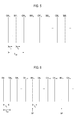
- the control unit 130 may calculate an aggregate time (T 1 + T 2 ) by adding the first time (T 1 ) to the second time (T 2 ), as illustrated in FIG. 5 and FIG. 6 .
- the control unit 130 may compare the aggregate time (T 1 + T 2 ) with the ultrasound data acquisition period (T CM ).
- the control unit 130 may control the first piece of ultrasound data (CM) and the second piece of ultrasound data (BM) to be provided alternately, as illustrated in FIG. 5 . If the aggregate time (T 1 + T 2 ) is equal to or greater than the ultrasound data acquisition period (T CM ), then the control unit 130 may control the first pieces of ultrasound data (CM) to be provided by the average number and then the second piece of ultrasound data (BM) to be provided once at the sweep speed (SP), as illustrated in FIG. 6 .
- control unit 130 may operate to control the setting of the M line and storage of the ultrasound data. Additionally, the control unit 130 may operate to control formation and display of the CM mode image and the BM mode image according to the ultrasound acquisition period and the ultrasound acquisition time.
- the ultrasound acquisition unit 140 may be operable to transmit an ultrasound signal to a target object, receive the ultrasound signal reflected from the target object (i.e., ultrasound echo signal), and provide the ultrasound data according to the control unit 130.
- FIG. 2 is a block diagram showing an illustrative embodiment of the ultrasound data acquisition unit 140.
- the ultrasound data acquisition unit 140 may include a transmit signal forming unit 210, a ultrasound probe 220 including a plurality of transducer elements, a beam former 230 and a ultrasound data forming unit 240.
- the transmit signal forming unit 210 may be operable to form a transmit signal to be applied to each of the transducer elements of the ultrasound probe 220.
- the positions and focusing points of the transducer elements may be considered in forming the transmit signal.
- the transmit signal may include a first transmit signal for acquiring the CM mode image and a second transmit signal for acquiring the BM mode image.
- the ultrasound probe 220 may operate to convert the transmit signal provided by the transmit signal forming unit 210 into an ultrasound signal and transmit it to the target object.
- the ultrasound probe 220 may further operate to receive the ultrasound echo signal reflected from the target object and form a receive signal.
- the ultrasound probe 220 may operate to convert the first transmit signal into an ultrasound signal, transmit it to the target object, receive the ultrasound echo signal reflected from the target object and form a first receive signal.
- the ultrasound probe 220 may operate to convert the second transmit signal into an ultrasound signal, transmit it to the target object, receive the ultrasound echo signal reflected from the target object and form a second receive signal.
- the beam former 230 may be configured to form a first digital signal through analog-to-digital conversion of the first receive signal when the first receive signal is provided by the ultrasound probe 220.
- the beam former 230 may perform receive-focusing upon the first digital signal in consideration of the positions and focusing points of the transducer elements of the ultrasound probe 220, and form a first receive-focused signal thereby.
- the beam former 230 may form a second digital signal through analog-to-digital conversion of the second receive signal when the second receive signal is provided by the ultrasound probe 220.
- the beam former 230 may perform receive-focusing upon the second digital signal in consideration of the positions and focusing points of the transducer elements of the ultrasound probe 220, and form a second receive-focused signal thereby.
- the ultrasound data forming unit 240 may be configured to form the first piece of ultrasound data using the first receive-focused signal when the first receive-focused signal is provided by the beam former 230. In one embodiment, the ultrasound data forming unit 240 may be configured to form the second piece of ultrasound data using the second receive-focused signal when the second receive-focused signal is provided by the beam former 230. Further, the ultrasound data forming unit 240 may perform various signal processing (e.g., gain adjustment, filtering) to the first and second receive-focused signal for forming the ultrasound data.
- various signal processing e.g., gain adjustment, filtering
- the storage unit 150 may be configured to store the first and second pieces of ultrasound data provided by the ultrasound data acquisition unit 140 according to the control unit 130.
- the storage unit 150 may be configured to store the first pieces of ultrasound data (CM) and the second pieces of ultrasound data (BM) in the order of being provided from the ultrasound data acquisition unit 140 according to the control unit 130, as illustrated in FIG. 7 .
- the storage unit 150 may be configured to store the first pieces of ultrasound data (CM) and the second pieces of ultrasound data (BM) in the order of being provided from the ultrasound data acquisition unit 140 according to the control unit 130, as illustrated in FIG. 8 .
- the storage unit 150 has been explained as storing the first pieces of ultrasound data and the second pieces of ultrasound data, the present invention is certainly not limited thereto.
- the storage unit 150 may include a first storage unit (not shown) for storing the first pieces of ultrasound data and a second storage unit (not shown) for storing the second pieces of ultrasound data.
- the image processor 160 may be operable to extract the first pieces of ultrasound data and the second pieces of ultrasound data in consideration of the sweep speed, the average number, the ultrasound data acquisition period and the ultrasound data acquisition time according to the control unit 130.
- the image processor 160 may further operate to form the CM mode image and the BM mode image based on the extracted first and second pieces of ultrasound data.
- FIG. 3 is a block diagram showing an illustrative embodiment of the image processor 160.
- the image processor 160 may include a determination unit 310, an extraction unit 320, a CM mode image forming unit 330 and a BM mode image forming unit 340.
- the determination unit 310 may be configured to form a determination result using the sweep speed, the average number, the ultrasound data acquisition period and the ultrasound data acquisition time. In one embodiment, the determination unit 310 may be configured to form first determination information if the ultrasound data acquisition time, which is the aggregate time (T 1 + T 2 ) calculated by adding the first time to the second time, is less than the ultrasound data acquisition period (T CM ), as illustrated in FIG. 5 . In one embodiment, the determination unit 310 may be configured to form second determination information if the aggregate time (T 1 + T 2 ) calculated by adding the first time to the second time is equal to or more than the ultrasound data acquisition period (T CM ), as illustrated in FIG. 6 .
- the extraction unit 320 may be configured to extract the first pieces of ultrasound data and the second pieces of ultrasound data based on the sweep speed when the first determination information is provided by the determination unit 310.
- the extraction unit 320 may be configured to extract a predetermined number (e.g., 12) of the first pieces of ultrasound data (CM 18 -CM 7 ) starting at the first piece of ultrasound data (CM 18 ), which is lastly stored during the sweep period, from the storage unit 150, as illustrated in FIG. 7 .
- the extraction unit 320 may further operate to extract the second piece of ultrasound data (BM 18 ), which is lastly stored during the sweep period, from the storage unit 150.
- the extraction unit 320 may be configured to extract a predetermined number (e.g., 12) of the first pieces of ultrasound data (CM 18 -CM 7 ) starting at the first piece of ultrasound data (CM 18 ), which is lastly stored during the sweep period, from the storage unit 150, as illustrated in FIG. 7 .
- the extraction unit 320 may further operate to extract a predetermined number (e.g., 12) of the second pieces of ultrasound data (BM 18 -BM 7 ) starting at the second piece of ultrasound data (BM 18 ), which is lastly stored during the sweep period, from the storage unit 150, as illustrated in FIG. 7 .
- the extraction unit 320 may be configured to extract a predetermined number of the first pieces of ultrasound data and the second pieces of ultrasound data accumulated during the sweep period from the storage unit 150 when the second determination information is provided by the determination unit 310.
- the extraction unit 320 may be configured to extract a predetermined number (e.g., 12) of the ultrasound data (i.e., ten of the first pieces of ultrasound data (CM 16 -CM 7 ) and two of the second pieces of ultrasound data (BM 2 , BM 1 ) starting at the second piece of ultrasound data (BM 2 ), which is lastly stored during the sweep period, from the storage unit 150, as illustrated in FIG. 8 .
- the CM mode image forming unit 330 may operate to form the CM mode image based on the first pieces of ultrasound data extracted by the extraction unit 320.
- the CM mode image forming unit 330 may operate to calculate mean power, mean velocity and variance corresponding to the CM mode image based on the first pieces of ultrasound data (CM 18 -CM 7 ) and form the CM mode image using the calculated mean power (P), mean velocity (v) and variance ( ⁇ 2 ).
- mean power, mean velocity and variance may be calculated according to the following equation (1).
- R[0] denotes 0 th order autocorrelation
- R[1] denotes 1 th order autocorrelation
- N denotes the average number
- x[n] denotes the input signal
- Im() denotes an imaginary part of a complex number
- Re() denotes a real part of the complex number.
- the CM mode image forming unit 330 may operate to calculate mean power, mean velocity and variance corresponding to the CM mode image using the first pieces of ultrasound data (CM 16 -CM 7 ), and form the CM mode image using the calculated mean power, mean velocity and variance.
- mean power (P), mean velocity (v) and variance ( ⁇ 2 ) may be calculated according to the following equation (2).
- the CM mode image forming unit 330 may operate to obtain third pieces of ultrasound data (CM 8 ' and CM 16 '), which were not provided at the sweep speed, with the use of interpolation of the first pieces of ultrasound data (CM 16 -CM 7 ) as illustrated in FIG. 9 .
- the CM mode image forming unit 330 may further operate to calculate an error comparing the first pieces of ultrasound data (CM 16 -CM 7 ) extracted by the extraction unit 320 with the third pieces of ultrasound data (CM 8 ' and CM 16 ') obtained by using the interpolation.
- the CM mode image forming unit 330 may operate to calculate mean power, mean velocity and variance using the first pieces of ultrasound data (CM 16 -CM 7 ) extracted by the extraction unit 320 and the third pieces of ultrasound data (CM 8 ' and CM 16 ') obtained by using the interpolation, and form the CM mode image using the calculated mean power, mean velocity and variance. Assuming that the number of third pieces of ultrasound data obtained by using the interpolation is K, the third pieces of ultrasound data obtained by using the interpolation are located at M, M+1, and the total number of the first and third pieces of ultrasound data is N.
- mean power (P total ), mean velocity (v total ) and variance ( ⁇ 2 total ) may be calculated according to the following equation (3).
- P IP , v IP and ⁇ 2 IP respectively represent mean power, mean velocity and variance, which are calculated from the third pieces of ultrasound data (CM 8 ' and CM 16 ') obtained by using the interpolation.
- the CM mode image forming unit 330 may operate to calculate mean power, mean velocity and variance only using the first pieces of ultrasound data (CM 16 -CM 7 ) extracted by the extraction unit 320, and form the CM mode image using the calculated mean power, mean velocity and variance.
- the BM mode image forming unit 340 may operate to form a BM mode image based on the second pieces of ultrasound data extracted by the extraction unit 320.
- the BM mode image forming unit 340 may operate to form the BM mode image based on the second piece of ultrasound data (BM 18 ).
- the BM mode image forming unit 340 may operate to form the BM mode image through performing, for example, line average to the second pieces of ultrasound data (BM 18 -BM 7 ).
- the BM mode image forming unit 340 may operate to form the BM mode image through performing, for example, line average to the second pieces of ultrasound data (BM 1 and BM 2 ).
- the display unit 170 may operate to display the CM mode image and the BM mode image formed at the image processor 160 according to the control unit 130.
- the display unit may further operate to display the B mode image 410, the color doppler mode image 420 and the M line 440, as illustrated in FIG. 4 .
- the display unit 170 may include a liquid crystal display (LCD), a cathode ray tube (CRT) or any other device capable of displaying an image.
- LCD liquid crystal display
- CRT cathode ray tube
Landscapes
- Engineering & Computer Science (AREA)
- Physics & Mathematics (AREA)
- Radar, Positioning & Navigation (AREA)
- Remote Sensing (AREA)
- Computer Networks & Wireless Communication (AREA)
- General Physics & Mathematics (AREA)
- Health & Medical Sciences (AREA)
- Life Sciences & Earth Sciences (AREA)
- Acoustics & Sound (AREA)
- Nuclear Medicine, Radiotherapy & Molecular Imaging (AREA)
- Molecular Biology (AREA)
- Pathology (AREA)
- Radiology & Medical Imaging (AREA)
- Biomedical Technology (AREA)
- Heart & Thoracic Surgery (AREA)
- Medical Informatics (AREA)
- Biophysics (AREA)
- Surgery (AREA)
- Animal Behavior & Ethology (AREA)
- General Health & Medical Sciences (AREA)
- Public Health (AREA)
- Veterinary Medicine (AREA)
- Ultra Sonic Daignosis Equipment (AREA)
Applications Claiming Priority (1)
| Application Number | Priority Date | Filing Date | Title |
|---|---|---|---|
| KR20090029678 | 2009-04-07 |
Publications (3)
| Publication Number | Publication Date |
|---|---|
| EP2238912A2 true EP2238912A2 (fr) | 2010-10-13 |
| EP2238912A3 EP2238912A3 (fr) | 2012-11-28 |
| EP2238912B1 EP2238912B1 (fr) | 2016-01-27 |
Family
ID=42340374
Family Applications (1)
| Application Number | Title | Priority Date | Filing Date |
|---|---|---|---|
| EP10157867.2A Active EP2238912B1 (fr) | 2009-04-07 | 2010-03-26 | Système à ultrasons et procédé pour la fourniture d'une image en mode M couleur et d'une image en mode M luminosité |
Country Status (4)
| Country | Link |
|---|---|
| US (1) | US8491478B2 (fr) |
| EP (1) | EP2238912B1 (fr) |
| JP (1) | JP5650430B2 (fr) |
| KR (1) | KR101117854B1 (fr) |
Families Citing this family (1)
| Publication number | Priority date | Publication date | Assignee | Title |
|---|---|---|---|---|
| KR101386099B1 (ko) * | 2011-12-27 | 2014-04-16 | 삼성메디슨 주식회사 | 벡터 모션 모드 영상을 제공하는 초음파 시스템 및 방법 |
Family Cites Families (17)
| Publication number | Priority date | Publication date | Assignee | Title |
|---|---|---|---|---|
| JPS6125534A (ja) * | 1984-07-16 | 1986-02-04 | 横河メディカルシステム株式会社 | 画像診断装置 |
| JPH0475645A (ja) * | 1990-07-19 | 1992-03-10 | Toshiba Corp | 超音波診断装置 |
| JP3386853B2 (ja) * | 1993-07-23 | 2003-03-17 | フクダ電子株式会社 | 超音波診断装置 |
| US5916168A (en) * | 1997-05-29 | 1999-06-29 | Advanced Technology Laboratories, Inc. | Three dimensional M-mode ultrasonic diagnostic imaging system |
| US5800356A (en) * | 1997-05-29 | 1998-09-01 | Advanced Technology Laboratories, Inc. | Ultrasonic diagnostic imaging system with doppler assisted tracking of tissue motion |
| US6050944A (en) * | 1997-06-17 | 2000-04-18 | Acuson Corporation | Method and apparatus for frequency control of an ultrasound system |
| US6537217B1 (en) * | 2001-08-24 | 2003-03-25 | Ge Medical Systems Global Technology Company, Llc | Method and apparatus for improved spatial and temporal resolution in ultrasound imaging |
| JP2004166897A (ja) | 2002-11-19 | 2004-06-17 | Aloka Co Ltd | 超音波診断装置 |
| EP1498746B1 (fr) * | 2003-07-09 | 2013-12-11 | Panasonic Corporation | Appareil diagnostique à ultrasons et dispositif de traitement d'une image tomographique |
| JP4520235B2 (ja) * | 2003-07-09 | 2010-08-04 | パナソニック株式会社 | 超音波診断装置および超音波診断方法 |
| JP2008515520A (ja) | 2004-10-07 | 2008-05-15 | コーニンクレッカ フィリップス エレクトロニクス エヌ ヴィ | 表示される画像データに関し一貫した解剖学的ビューを維持するための方法及びシステム |
| JP4653454B2 (ja) * | 2004-10-22 | 2011-03-16 | 株式会社東芝 | 超音波診断装置、及びこの装置の制御プログラム |
| KR100748178B1 (ko) * | 2005-01-05 | 2007-08-09 | 주식회사 메디슨 | 임의 m-모드 영상을 디스플레이하는 초음파 진단 시스템및 방법 |
| CN100525711C (zh) * | 2005-08-29 | 2009-08-12 | 深圳迈瑞生物医疗电子股份有限公司 | 基于运动插值的解剖m型成像方法和装置 |
| US7670293B2 (en) * | 2005-10-17 | 2010-03-02 | General Electric Company | Method and system for scan sequencing in an ultrasound imaging system |
| KR100961854B1 (ko) * | 2007-03-16 | 2010-06-09 | 주식회사 메디슨 | 도플러 스펙트럼 영상을 디스플레이하기 위한 초음파 진단시스템 및 방법 |
| JP2008272033A (ja) * | 2007-04-26 | 2008-11-13 | Ge Medical Systems Global Technology Co Llc | 超音波撮像装置 |
-
2010
- 2010-03-26 EP EP10157867.2A patent/EP2238912B1/fr active Active
- 2010-04-06 JP JP2010088049A patent/JP5650430B2/ja not_active Expired - Fee Related
- 2010-04-07 KR KR1020100031847A patent/KR101117854B1/ko active Active
- 2010-04-07 US US12/756,000 patent/US8491478B2/en active Active
Non-Patent Citations (1)
| Title |
|---|
| None |
Also Published As
| Publication number | Publication date |
|---|---|
| US20100256491A1 (en) | 2010-10-07 |
| JP2010240431A (ja) | 2010-10-28 |
| EP2238912B1 (fr) | 2016-01-27 |
| JP5650430B2 (ja) | 2015-01-07 |
| EP2238912A3 (fr) | 2012-11-28 |
| US8491478B2 (en) | 2013-07-23 |
| KR101117854B1 (ko) | 2012-03-16 |
| KR20100111633A (ko) | 2010-10-15 |
Similar Documents
| Publication | Publication Date | Title |
|---|---|---|
| US8684934B2 (en) | Adaptively performing clutter filtering in an ultrasound system | |
| US9554770B2 (en) | High pulse repetition frequency for detection of tissue mechanical property with ultrasound | |
| JP3746115B2 (ja) | 超音波診断装置 | |
| JP7295296B2 (ja) | 超音波診断装置および超音波診断装置の制御方法 | |
| US8343054B1 (en) | Methods and apparatus for ultrasound imaging | |
| EP1967866A1 (fr) | Appareil à ultrasons et méthode de diagnostic à ultrasons | |
| EP4061234B1 (fr) | Réduction d'artefact de réverbération dans des images ultrasonores et dispositifs, systèmes et procédés associés | |
| US20080177182A1 (en) | Ultrasonic imaging apparatus and method for acquiring ultrasonic image | |
| CN107049361B (zh) | 使用剪切波的声音速度成像 | |
| KR20150033585A (ko) | 분석 데이터로부터 전단파 추정 | |
| US10675007B2 (en) | Frequency compounding in elasticity imaging | |
| EP1793343A1 (fr) | Système de traitement d'images et procédé d'amélioration de la qualité d'une image ultrasonore | |
| JP2010259799A (ja) | クラッタ信号をフィルタリングするための固有ベクトル設定方法およびこれを用いた超音波システム | |
| EP3133419B1 (fr) | Appareil de diagnostic à ultrasons et procédé de génération d'image à forme d'onde doppler | |
| US11039777B2 (en) | Ultrasonic diagnostic apparatus and control method | |
| US7022078B2 (en) | Method and apparatus for spectral strain rate visualization | |
| US8348848B1 (en) | Methods and apparatus for ultrasound imaging | |
| JP5467783B2 (ja) | 超音波システム及びクラッタ信号フィルタリング方法 | |
| CN107427281B (zh) | 超声波诊断装置 | |
| US9091760B2 (en) | Performing receive-focusing based on mid-point algorithm in ultrasound system | |
| US20200077986A1 (en) | Angles for ultrasound-based shear wave imaging | |
| KR101055500B1 (ko) | Bc-모드 영상을 형성하는 초음파 시스템 및 방법 | |
| EP2199827A2 (fr) | Filtrage de signal d'écho parasite pour un signal de Doppler | |
| US20060030777A1 (en) | T-statistic method for suppressing artifacts in blood vessel ultrasonic imaging | |
| US8491478B2 (en) | Ultrasound system and method of providing color M mode image and brightness M mode image |
Legal Events
| Date | Code | Title | Description |
|---|---|---|---|
| PUAI | Public reference made under article 153(3) epc to a published international application that has entered the european phase |
Free format text: ORIGINAL CODE: 0009012 |
|
| AK | Designated contracting states |
Kind code of ref document: A2 Designated state(s): AT BE BG CH CY CZ DE DK EE ES FI FR GB GR HR HU IE IS IT LI LT LU LV MC MK MT NL NO PL PT RO SE SI SK SM TR |
|
| AX | Request for extension of the european patent |
Extension state: AL BA ME RS |
|
| PUAL | Search report despatched |
Free format text: ORIGINAL CODE: 0009013 |
|
| AK | Designated contracting states |
Kind code of ref document: A3 Designated state(s): AT BE BG CH CY CZ DE DK EE ES FI FR GB GR HR HU IE IS IT LI LT LU LV MC MK MT NL NO PL PT RO SE SI SK SM TR |
|
| AX | Request for extension of the european patent |
Extension state: AL BA ME RS |
|
| RIC1 | Information provided on ipc code assigned before grant |
Ipc: G01S 7/52 20060101ALI20121019BHEP Ipc: G01S 15/89 20060101ALI20121019BHEP Ipc: A61B 8/08 20060101AFI20121019BHEP |
|
| 17P | Request for examination filed |
Effective date: 20130523 |
|
| RBV | Designated contracting states (corrected) |
Designated state(s): AT BE BG CH CY CZ DE DK EE ES FI FR GB GR HR HU IE IS IT LI LT LU LV MC MK MT NL NO PL PT RO SE SI SK SM TR |
|
| 17Q | First examination report despatched |
Effective date: 20130617 |
|
| RIC1 | Information provided on ipc code assigned before grant |
Ipc: A61B 8/06 20060101ALN20150804BHEP Ipc: G01S 15/89 20060101ALI20150804BHEP Ipc: G01S 7/52 20060101ALI20150804BHEP Ipc: A61B 8/08 20060101AFI20150804BHEP |
|
| GRAP | Despatch of communication of intention to grant a patent |
Free format text: ORIGINAL CODE: EPIDOSNIGR1 |
|
| INTG | Intention to grant announced |
Effective date: 20150928 |
|
| RIN1 | Information on inventor provided before grant (corrected) |
Inventor name: KIM, JONG SIK Inventor name: LEE, KWANG JU |
|
| GRAS | Grant fee paid |
Free format text: ORIGINAL CODE: EPIDOSNIGR3 |
|
| RAP1 | Party data changed (applicant data changed or rights of an application transferred) |
Owner name: SAMSUNG MEDISON CO., LTD. |
|
| GRAA | (expected) grant |
Free format text: ORIGINAL CODE: 0009210 |
|
| AK | Designated contracting states |
Kind code of ref document: B1 Designated state(s): AT BE BG CH CY CZ DE DK EE ES FI FR GB GR HR HU IE IS IT LI LT LU LV MC MK MT NL NO PL PT RO SE SI SK SM TR |
|
| REG | Reference to a national code |
Ref country code: GB Ref legal event code: FG4D |
|
| REG | Reference to a national code |
Ref country code: CH Ref legal event code: EP |
|
| REG | Reference to a national code |
Ref country code: AT Ref legal event code: REF Ref document number: 772291 Country of ref document: AT Kind code of ref document: T Effective date: 20160215 |
|
| REG | Reference to a national code |
Ref country code: IE Ref legal event code: FG4D |
|
| REG | Reference to a national code |
Ref country code: FR Ref legal event code: PLFP Year of fee payment: 7 |
|
| REG | Reference to a national code |
Ref country code: DE Ref legal event code: R096 Ref document number: 602010030297 Country of ref document: DE |
|
| REG | Reference to a national code |
Ref country code: NL Ref legal event code: FP |
|
| REG | Reference to a national code |
Ref country code: LT Ref legal event code: MG4D |
|
| REG | Reference to a national code |
Ref country code: AT Ref legal event code: MK05 Ref document number: 772291 Country of ref document: AT Kind code of ref document: T Effective date: 20160127 |
|
| PG25 | Lapsed in a contracting state [announced via postgrant information from national office to epo] |
Ref country code: GR Free format text: LAPSE BECAUSE OF FAILURE TO SUBMIT A TRANSLATION OF THE DESCRIPTION OR TO PAY THE FEE WITHIN THE PRESCRIBED TIME-LIMIT Effective date: 20160428 Ref country code: FI Free format text: LAPSE BECAUSE OF FAILURE TO SUBMIT A TRANSLATION OF THE DESCRIPTION OR TO PAY THE FEE WITHIN THE PRESCRIBED TIME-LIMIT Effective date: 20160127 Ref country code: HR Free format text: LAPSE BECAUSE OF FAILURE TO SUBMIT A TRANSLATION OF THE DESCRIPTION OR TO PAY THE FEE WITHIN THE PRESCRIBED TIME-LIMIT Effective date: 20160127 Ref country code: NO Free format text: LAPSE BECAUSE OF FAILURE TO SUBMIT A TRANSLATION OF THE DESCRIPTION OR TO PAY THE FEE WITHIN THE PRESCRIBED TIME-LIMIT Effective date: 20160427 Ref country code: ES Free format text: LAPSE BECAUSE OF FAILURE TO SUBMIT A TRANSLATION OF THE DESCRIPTION OR TO PAY THE FEE WITHIN THE PRESCRIBED TIME-LIMIT Effective date: 20160127 |
|
| PG25 | Lapsed in a contracting state [announced via postgrant information from national office to epo] |
Ref country code: LV Free format text: LAPSE BECAUSE OF FAILURE TO SUBMIT A TRANSLATION OF THE DESCRIPTION OR TO PAY THE FEE WITHIN THE PRESCRIBED TIME-LIMIT Effective date: 20160127 Ref country code: BE Free format text: LAPSE BECAUSE OF NON-PAYMENT OF DUE FEES Effective date: 20160331 Ref country code: AT Free format text: LAPSE BECAUSE OF FAILURE TO SUBMIT A TRANSLATION OF THE DESCRIPTION OR TO PAY THE FEE WITHIN THE PRESCRIBED TIME-LIMIT Effective date: 20160127 Ref country code: LT Free format text: LAPSE BECAUSE OF FAILURE TO SUBMIT A TRANSLATION OF THE DESCRIPTION OR TO PAY THE FEE WITHIN THE PRESCRIBED TIME-LIMIT Effective date: 20160127 Ref country code: PL Free format text: LAPSE BECAUSE OF FAILURE TO SUBMIT A TRANSLATION OF THE DESCRIPTION OR TO PAY THE FEE WITHIN THE PRESCRIBED TIME-LIMIT Effective date: 20160127 Ref country code: IS Free format text: LAPSE BECAUSE OF FAILURE TO SUBMIT A TRANSLATION OF THE DESCRIPTION OR TO PAY THE FEE WITHIN THE PRESCRIBED TIME-LIMIT Effective date: 20160527 Ref country code: PT Free format text: LAPSE BECAUSE OF FAILURE TO SUBMIT A TRANSLATION OF THE DESCRIPTION OR TO PAY THE FEE WITHIN THE PRESCRIBED TIME-LIMIT Effective date: 20160527 Ref country code: SE Free format text: LAPSE BECAUSE OF FAILURE TO SUBMIT A TRANSLATION OF THE DESCRIPTION OR TO PAY THE FEE WITHIN THE PRESCRIBED TIME-LIMIT Effective date: 20160127 |
|
| REG | Reference to a national code |
Ref country code: DE Ref legal event code: R097 Ref document number: 602010030297 Country of ref document: DE |
|
| PG25 | Lapsed in a contracting state [announced via postgrant information from national office to epo] |
Ref country code: EE Free format text: LAPSE BECAUSE OF FAILURE TO SUBMIT A TRANSLATION OF THE DESCRIPTION OR TO PAY THE FEE WITHIN THE PRESCRIBED TIME-LIMIT Effective date: 20160127 Ref country code: LU Free format text: LAPSE BECAUSE OF FAILURE TO SUBMIT A TRANSLATION OF THE DESCRIPTION OR TO PAY THE FEE WITHIN THE PRESCRIBED TIME-LIMIT Effective date: 20160326 Ref country code: MC Free format text: LAPSE BECAUSE OF FAILURE TO SUBMIT A TRANSLATION OF THE DESCRIPTION OR TO PAY THE FEE WITHIN THE PRESCRIBED TIME-LIMIT Effective date: 20160127 Ref country code: DK Free format text: LAPSE BECAUSE OF FAILURE TO SUBMIT A TRANSLATION OF THE DESCRIPTION OR TO PAY THE FEE WITHIN THE PRESCRIBED TIME-LIMIT Effective date: 20160127 |
|
| REG | Reference to a national code |
Ref country code: CH Ref legal event code: PL |
|
| PG25 | Lapsed in a contracting state [announced via postgrant information from national office to epo] |
Ref country code: RO Free format text: LAPSE BECAUSE OF FAILURE TO SUBMIT A TRANSLATION OF THE DESCRIPTION OR TO PAY THE FEE WITHIN THE PRESCRIBED TIME-LIMIT Effective date: 20160127 Ref country code: SM Free format text: LAPSE BECAUSE OF FAILURE TO SUBMIT A TRANSLATION OF THE DESCRIPTION OR TO PAY THE FEE WITHIN THE PRESCRIBED TIME-LIMIT Effective date: 20160127 Ref country code: CZ Free format text: LAPSE BECAUSE OF FAILURE TO SUBMIT A TRANSLATION OF THE DESCRIPTION OR TO PAY THE FEE WITHIN THE PRESCRIBED TIME-LIMIT Effective date: 20160127 Ref country code: SK Free format text: LAPSE BECAUSE OF FAILURE TO SUBMIT A TRANSLATION OF THE DESCRIPTION OR TO PAY THE FEE WITHIN THE PRESCRIBED TIME-LIMIT Effective date: 20160127 |
|
| PLBE | No opposition filed within time limit |
Free format text: ORIGINAL CODE: 0009261 |
|
| STAA | Information on the status of an ep patent application or granted ep patent |
Free format text: STATUS: NO OPPOSITION FILED WITHIN TIME LIMIT |
|
| GBPC | Gb: european patent ceased through non-payment of renewal fee |
Effective date: 20160427 |
|
| REG | Reference to a national code |
Ref country code: IE Ref legal event code: MM4A |
|
| PG25 | Lapsed in a contracting state [announced via postgrant information from national office to epo] |
Ref country code: BE Free format text: LAPSE BECAUSE OF FAILURE TO SUBMIT A TRANSLATION OF THE DESCRIPTION OR TO PAY THE FEE WITHIN THE PRESCRIBED TIME-LIMIT Effective date: 20160127 |
|
| 26N | No opposition filed |
Effective date: 20161028 |
|
| PG25 | Lapsed in a contracting state [announced via postgrant information from national office to epo] |
Ref country code: LI Free format text: LAPSE BECAUSE OF NON-PAYMENT OF DUE FEES Effective date: 20160331 Ref country code: IE Free format text: LAPSE BECAUSE OF NON-PAYMENT OF DUE FEES Effective date: 20160326 Ref country code: GB Free format text: LAPSE BECAUSE OF NON-PAYMENT OF DUE FEES Effective date: 20160427 Ref country code: CH Free format text: LAPSE BECAUSE OF NON-PAYMENT OF DUE FEES Effective date: 20160331 |
|
| REG | Reference to a national code |
Ref country code: FR Ref legal event code: PLFP Year of fee payment: 8 |
|
| PG25 | Lapsed in a contracting state [announced via postgrant information from national office to epo] |
Ref country code: SI Free format text: LAPSE BECAUSE OF FAILURE TO SUBMIT A TRANSLATION OF THE DESCRIPTION OR TO PAY THE FEE WITHIN THE PRESCRIBED TIME-LIMIT Effective date: 20160127 Ref country code: BG Free format text: LAPSE BECAUSE OF FAILURE TO SUBMIT A TRANSLATION OF THE DESCRIPTION OR TO PAY THE FEE WITHIN THE PRESCRIBED TIME-LIMIT Effective date: 20160427 |
|
| PG25 | Lapsed in a contracting state [announced via postgrant information from national office to epo] |
Ref country code: MT Free format text: LAPSE BECAUSE OF FAILURE TO SUBMIT A TRANSLATION OF THE DESCRIPTION OR TO PAY THE FEE WITHIN THE PRESCRIBED TIME-LIMIT Effective date: 20160127 |
|
| REG | Reference to a national code |
Ref country code: FR Ref legal event code: PLFP Year of fee payment: 9 |
|
| PG25 | Lapsed in a contracting state [announced via postgrant information from national office to epo] |
Ref country code: CY Free format text: LAPSE BECAUSE OF FAILURE TO SUBMIT A TRANSLATION OF THE DESCRIPTION OR TO PAY THE FEE WITHIN THE PRESCRIBED TIME-LIMIT Effective date: 20160127 Ref country code: HU Free format text: LAPSE BECAUSE OF FAILURE TO SUBMIT A TRANSLATION OF THE DESCRIPTION OR TO PAY THE FEE WITHIN THE PRESCRIBED TIME-LIMIT; INVALID AB INITIO Effective date: 20100326 |
|
| PG25 | Lapsed in a contracting state [announced via postgrant information from national office to epo] |
Ref country code: MT Free format text: LAPSE BECAUSE OF FAILURE TO SUBMIT A TRANSLATION OF THE DESCRIPTION OR TO PAY THE FEE WITHIN THE PRESCRIBED TIME-LIMIT Effective date: 20160331 Ref country code: MK Free format text: LAPSE BECAUSE OF FAILURE TO SUBMIT A TRANSLATION OF THE DESCRIPTION OR TO PAY THE FEE WITHIN THE PRESCRIBED TIME-LIMIT Effective date: 20160127 Ref country code: TR Free format text: LAPSE BECAUSE OF FAILURE TO SUBMIT A TRANSLATION OF THE DESCRIPTION OR TO PAY THE FEE WITHIN THE PRESCRIBED TIME-LIMIT Effective date: 20160127 |
|
| PGFP | Annual fee paid to national office [announced via postgrant information from national office to epo] |
Ref country code: NL Payment date: 20200206 Year of fee payment: 11 |
|
| REG | Reference to a national code |
Ref country code: NL Ref legal event code: MM Effective date: 20210401 |
|
| PG25 | Lapsed in a contracting state [announced via postgrant information from national office to epo] |
Ref country code: NL Free format text: LAPSE BECAUSE OF NON-PAYMENT OF DUE FEES Effective date: 20210401 |
|
| PGFP | Annual fee paid to national office [announced via postgrant information from national office to epo] |
Ref country code: IT Payment date: 20250206 Year of fee payment: 16 |
|
| PGFP | Annual fee paid to national office [announced via postgrant information from national office to epo] |
Ref country code: DE Payment date: 20260320 Year of fee payment: 17 |
|
| PGFP | Annual fee paid to national office [announced via postgrant information from national office to epo] |
Ref country code: FR Payment date: 20260324 Year of fee payment: 17 |