EP2239058A2 - Wear-resistant roll and method of making it - Google Patents
Wear-resistant roll and method of making it Download PDFInfo
- Publication number
- EP2239058A2 EP2239058A2 EP10158122A EP10158122A EP2239058A2 EP 2239058 A2 EP2239058 A2 EP 2239058A2 EP 10158122 A EP10158122 A EP 10158122A EP 10158122 A EP10158122 A EP 10158122A EP 2239058 A2 EP2239058 A2 EP 2239058A2
- Authority
- EP
- European Patent Office
- Prior art keywords
- studs
- roll
- welding
- matrix material
- wear
- Prior art date
- Legal status (The legal status is an assumption and is not a legal conclusion. Google has not performed a legal analysis and makes no representation as to the accuracy of the status listed.)
- Granted
Links
Images

Classifications
-
- B—PERFORMING OPERATIONS; TRANSPORTING
- B02—CRUSHING, PULVERISING, OR DISINTEGRATING; PREPARATORY TREATMENT OF GRAIN FOR MILLING
- B02C—CRUSHING, PULVERISING, OR DISINTEGRATING IN GENERAL; MILLING GRAIN
- B02C4/00—Crushing or disintegrating by roller mills
- B02C4/28—Details
- B02C4/30—Shape or construction of rollers
- B02C4/305—Wear resistant rollers
-
- B—PERFORMING OPERATIONS; TRANSPORTING
- B23—MACHINE TOOLS; METAL-WORKING NOT OTHERWISE PROVIDED FOR
- B23K—SOLDERING OR UNSOLDERING; WELDING; CLADDING OR PLATING BY SOLDERING OR WELDING; CUTTING BY APPLYING HEAT LOCALLY, e.g. FLAME CUTTING; WORKING BY LASER BEAM
- B23K35/00—Rods, electrodes, materials, or media, for use in soldering, welding, or cutting
- B23K35/22—Rods, electrodes, materials, or media, for use in soldering, welding, or cutting characterised by the composition or nature of the material
- B23K35/24—Selection of soldering or welding materials proper
- B23K35/30—Selection of soldering or welding materials proper with the principal constituent melting at less than 1550°C
- B23K35/3053—Fe as the principal constituent
Definitions
- the present invention relates to an improved roll construction for a roller press, comprising a cylindrical press roll having an outer cylindrical pressing surface for use with an opposing roll, and a plurality of wear-resistant surface members (studs), wherein the free ends of the studs protrude radially from the surface of the roll and spaces between the studs are filled with a matrix material.
- a cylindrical press roll having an outer cylindrical pressing surface for use with an opposing roll
- a plurality of wear-resistant surface members (studs) wherein the free ends of the studs protrude radially from the surface of the roll and spaces between the studs are filled with a matrix material.
- the present invention relates to a method of making the roll.
- HPRG High Pressure Roller Grinding
- HEXADUR® process provides a highly abrasion resistant material for wear protection for grinding rollers.
- the name HEXADUR has been derived from the shape and arrangement of hard metal hexagons which are fixed by hot isostatic pressed (HIP) on to a base metal via a matrix.
- HIP hot isostatic pressed
- a second system is the "Polycom process" which focused on placing studs in holes drilled into the surface of the roller.
- the core of the patent is that the stud surface is raised above the surface of the roller.
- the ground stone/cement then fills in the space between the studs and acts as an auto protection for the studs.
- the matrix and the tile are the same height and it does not use HIP.
- Cost of the WC tiles is high; impact resistance of sintered WC tiles is low; the WC tiles are only bonded by a thin film of Ni-based matrix and there is a risk they detach, there is a limit to the thickness of the tiles and thick roller layers need to be made up of several layers, with all interface problems that could bring and the additional costs.
- An object of the invention is to provide an improved pressing roller which is capable of operating in an extremely high force nip environment with markedly reduced wear of the grinding surface as compared with rolls having constructions of the type heretofore known in the art.
- a roll having the features of claim 1. It is characterized by studs which are fixed by welding to the roll, and the matrix material being softer than the hardest material of which the studs are made.
- the basic idea is to use a wear resistant stud that is welded to the roller base. It serves as a replacement for hard particles (WC) or metal insert members as known in the prior art (Hexadur tile or Polycom system).
- WC hard particles
- metal insert members as known in the prior art (Hexadur tile or Polycom system).
- the matrix is usually an alloy based on Ni or Fe. It can be made by deposition from a wire, electrode, powder deposited by the usual methods (welding, PTA, brazing, spraying), thereby flooding around the studs.
- the studs are stabilized by the matrix material and additionally - with operation for grounding material - by the ground material itself.
- the reason for that is that as a result of wear of the softer matrix material the studs will protrude from the matrix as to form pockets between adjacent studs, and the pockets will be filled with ground material. Therefore, shortly after beginning of the operation for grounding material, nearly the whole outer surface of the roll is covered with the grounded material having the same hardness as the material to be grounded.
- the grounded material is best suited for stabilizing the studs and protecting the softer matrix material from further wear.
- flood welding is performed with PTA.
- PTA flood welding was coined to describe a unique method of depositing vast amounts of weld metal.
- the studs are fixed on the roll by bold welding. This is a fast process which does not require the making of holes for inserting any inserting members.
- studs which comprise a wear resistant core, surrounded by a metal stud casing.
- the studs may be such elements as known from DE 20 2004 007 809 U1 , made of low cost steel with a head that has a wear resistant pellet integrated into its design.
- a method comprising the features of claim 8. It comprises the following steps: forming a cylindrical press roll having an outer cylindrical pressing surface for use with an opposing roll, fixing a plurality of wear resistant surface members (studs) to the roll surface at spaced intervals having a hardness greater than the roll surface, so that free ends of the studs protrude radially from the surface of the roll, and filing the spaces between the studs with a matrix material, whereby the studs are fixed by welding to the roll, and the matrix material being softer than the hardest material of which the studs are made.
- studs wear resistant surface members
- the basic idea is to use a wear resistant stud that is welded to the roller base. Fixing of the studs by welding is a fast and reliable low cost process.
- the studs are stabilized by the matrix material and additionally - with operation for grounding material - by the ground material itself. The reason for that is that as a result of wear of the softer matrix material the studs will protrude from the matrix as to form pockets between adjacent studs, and the pockets will be filled with ground material. Therefore, shortly after beginning of the operation for grounding material, nearly the whole outer surface of the roll is covered with the grounded material having the same hardness as the material to be grounded.
- the grounded material is best suited for stabilizing the studs and protecting the softer matrix material from further wear.
- the filling of the spaces between the studs is performed by flood welding.
- the flood welding is preferably performed with PTA.
- At least a part of the studs is made from an iron based alloy. And the studs are fixed on the roll by bold welding.
- the explanation above refers to a wear resistant surface layer of a milling member in form of a roll. Apart from this the same design of the wear resistant surface layer and the same method for producing the surface layer can be applied to a milling member in form of a plate.
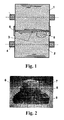
- Fig. 1 illustrates a two roller press for comminution of granular material by interparticle crushing.
- the press is formed between cylindrical rolls 1 and 2 which form a press nip 3 therebetween.
- the rolls are suitably supported on high force bearings 4 with means for adjusting the nip width and pressure to obtain the nip forces required for interparticle crushing.
- Granular material is supplied from above the nip by a suitable product delivery shaft.
- End plates 5 positioned at the end of the nip 3 for aiding in retaining material and preventing it from exiting axially out the ends of the nip 3.
- a suitable receiving means is provided beneath the nip for receiving the comminuted material.
- a plurality of wear-resistant studs 6 are shown, which are welded to the cylindrical surface of the rolls 1, 2.
- Fig. 2 shows a photo of a stud 6 in a longitudinal cross section.
- the stud 6 is made of a wear resistant core 7 made of an Fe-based alloy, surrounded by a metal stud casing 9 made of a tough steel and a base 8 made of low cost steel.
- Such studs are known from DE 20 2004 007 809 U1 which is incorporated into this patent application by reference.
- a preferred process for manufacturing the rolls 1, 2 is shown.
- the studs 6 are welded the surface of the roll 1 by bold welding ( Fig. 3 ).
- the space between the studs 6 is filled with a matrix material (Ni-based alloy) which is softer than the casing 9 of the studs 6 by flood welding with PTA.
- the studs 6 are completely embedded in the matrix material having the same height as the stud top ( Fig. 4 ).
- the studs 6 will protrude from the matrix 11 and pockets 12 will form between the studs 6 ( Fig. 5 ).
- the pockets 12 will be filled with ground material 13.
- the resulting surface is essentially flat and it consists of compacted wear and grounded material and the studs, whereby the compacted wear and grounded material works as an optimal embedding for the studs.
Landscapes
- Engineering & Computer Science (AREA)
- Mechanical Engineering (AREA)
- Food Science & Technology (AREA)
- Rolls And Other Rotary Bodies (AREA)
- Crushing And Grinding (AREA)
Abstract
Description
- The present invention relates to an improved roll construction for a roller press, comprising a cylindrical press roll having an outer cylindrical pressing surface for use with an opposing roll, and a plurality of wear-resistant surface members (studs), wherein the free ends of the studs protrude radially from the surface of the roll and spaces between the studs are filled with a matrix material.
- Furthermore, the present invention relates to a method of making the roll.
- In the mineral and cement industries hard particles need to be ground to small fractions. A number of methods exist and a leading and growing method is High Pressure Roller Grinding (HPRG). Equipment availability and the overall cost of grinding facilities utilizing roller presses are significantly influenced by the service life of wear parts, in particular the durability of the grinding rollers.
- There is a need in design for a coating on the rollers to protect them against wear. In the past this was simple weld overlay with FeCr alloys. To increase the wear resistance, it was realized that there must be a move from weld overlay to harder materials and several systems were developed.
- One system is the HEXADUR® process, which provides a highly abrasion resistant material for wear protection for grinding rollers. The name HEXADUR has been derived from the shape and arrangement of hard metal hexagons which are fixed by hot isostatic pressed (HIP) on to a base metal via a matrix.
- The disadvantages are the expense, limited size of the parts that can be produced, as well as lack of repair on site possibilities.
- A second system is the "Polycom process" which focused on placing studs in holes drilled into the surface of the roller. The core of the patent is that the stud surface is raised above the surface of the roller. The ground stone/cement then fills in the space between the studs and acts as an auto protection for the studs.
- Another process has been found that uses sintered WCCo tiles and "flood weld" them using plasma transferred arc (PTA) or other welding process with a Nickel based matrix with a slightly softer hardness.
- The matrix and the tile are the same height and it does not use HIP. However, it still has several disadvantages: Cost of the WC tiles is high; impact resistance of sintered WC tiles is low; the WC tiles are only bonded by a thin film of Ni-based matrix and there is a risk they detach, there is a limit to the thickness of the tiles and thick roller layers need to be made up of several layers, with all interface problems that could bring and the additional costs.
- An object of the invention is to provide an improved pressing roller which is capable of operating in an extremely high force nip environment with markedly reduced wear of the grinding surface as compared with rolls having constructions of the type heretofore known in the art.
- It is a further object of the invention to provide a fast and low cost method for manufacturing a roll for a roller press with high reliability.
- With respect to the roll for a roller press this object is achieved by a roll having the features of
claim 1. It is characterized by studs which are fixed by welding to the roll, and the matrix material being softer than the hardest material of which the studs are made. - The basic idea is to use a wear resistant stud that is welded to the roller base. It serves as a replacement for hard particles (WC) or metal insert members as known in the prior art (Hexadur tile or Polycom system).
- The matrix is usually an alloy based on Ni or Fe. It can be made by deposition from a wire, electrode, powder deposited by the usual methods (welding, PTA, brazing, spraying), thereby flooding around the studs.
- The studs are stabilized by the matrix material and additionally - with operation for grounding material - by the ground material itself. The reason for that is that as a result of wear of the softer matrix material the studs will protrude from the matrix as to form pockets between adjacent studs, and the pockets will be filled with ground material. Therefore, shortly after beginning of the operation for grounding material, nearly the whole outer surface of the roll is covered with the grounded material having the same hardness as the material to be grounded. The grounded material is best suited for stabilizing the studs and protecting the softer matrix material from further wear.
- The following are preferred embodiments of the roll.
- Filling the spaces between the studs is performed by flood welding. Preferably flood welding is performed with PTA. The term flood welding was coined to describe a unique method of depositing vast amounts of weld metal.
- Flood welding occurs such that before operation of the roll in a grinding process, the free ends of the embedded have nearly the same level as the matrix material.
- Low cost and good weldability can achieved if t at least a part of the studs is made of an iron based alloy.
- Preferably, the studs are fixed on the roll by bold welding. This is a fast process which does not require the making of holes for inserting any inserting members.
- Good results were achieved by using studs which comprise a wear resistant core, surrounded by a metal stud casing. The studs may be such elements as known from
DE 20 2004 007 809 U1 , made of low cost steel with a head that has a wear resistant pellet integrated into its design. - With respect to the method of manufacturing a roll for a roller press the above object is achieved by a method comprising the features of claim 8. It comprises the following steps: forming a cylindrical press roll having an outer cylindrical pressing surface for use with an opposing roll, fixing a plurality of wear resistant surface members (studs) to the roll surface at spaced intervals having a hardness greater than the roll surface, so that free ends of the studs protrude radially from the surface of the roll, and filing the spaces between the studs with a matrix material, whereby the studs are fixed by welding to the roll, and the matrix material being softer than the hardest material of which the studs are made.
- The basic idea is to use a wear resistant stud that is welded to the roller base. Fixing of the studs by welding is a fast and reliable low cost process. The studs are stabilized by the matrix material and additionally - with operation for grounding material - by the ground material itself. The reason for that is that as a result of wear of the softer matrix material the studs will protrude from the matrix as to form pockets between adjacent studs, and the pockets will be filled with ground material. Therefore, shortly after beginning of the operation for grounding material, nearly the whole outer surface of the roll is covered with the grounded material having the same hardness as the material to be grounded. The grounded material is best suited for stabilizing the studs and protecting the softer matrix material from further wear.
- The following are preferred embodiments of the method.
- The filling of the spaces between the studs is performed by flood welding. The flood welding is preferably performed with PTA.
- At least a part of the studs is made from an iron based alloy. And the studs are fixed on the roll by bold welding.
- The explanation above refers to a wear resistant surface layer of a milling member in form of a roll. Apart from this the same design of the wear resistant surface layer and the same method for producing the surface layer can be applied to a milling member in form of a plate.
- In the drawings schematically
- Fig.1
- a plan view of opposed grinding rolls of a two roller machine employing welded wear-resistant studs in accordance with the principles of the invention,
- Fig. 2
- a preferred embodiment of a stud welded to the rolls shown in
Fig. 1 in a cross section, - Fig. 3 to Fig. 6
- process steps for making the rolls of
Fig. 1 according of the method of the invention. -
Fig. 1 illustrates a two roller press for comminution of granular material by interparticle crushing. The press is formed betweencylindrical rolls high force bearings 4 with means for adjusting the nip width and pressure to obtain the nip forces required for interparticle crushing. Granular material is supplied from above the nip by a suitable product delivery shaft.End plates 5 positioned at the end of thenip 3 for aiding in retaining material and preventing it from exiting axially out the ends of thenip 3. A suitable receiving means is provided beneath the nip for receiving the comminuted material. In a partial view a plurality of wear-resistant studs 6 are shown, which are welded to the cylindrical surface of therolls -
Fig. 2 shows a photo of astud 6 in a longitudinal cross section. Thestud 6 is made of a wear resistant core 7 made of an Fe-based alloy, surrounded by ametal stud casing 9 made of a tough steel and a base 8 made of low cost steel. Such studs are known fromDE 20 2004 007 809 U1 which is incorporated into this patent application by reference. - In
Fig. 3 to 6 a preferred process for manufacturing therolls studs 6 are welded the surface of theroll 1 by bold welding (Fig. 3 ). Then, the space between thestuds 6 is filled with a matrix material (Ni-based alloy) which is softer than thecasing 9 of thestuds 6 by flood welding with PTA. As a result, thestuds 6 are completely embedded in the matrix material having the same height as the stud top (Fig. 4 ). With operation and wear of the matrix material, thestuds 6 will protrude from thematrix 11 and pockets 12 will form between the studs 6 (Fig. 5 ). Thepockets 12 will be filled withground material 13. The resulting surface is essentially flat and it consists of compacted wear and grounded material and the studs, whereby the compacted wear and grounded material works as an optimal embedding for the studs. - The invention has the following advantages:
- Welded with large surface area
- good bonding of the hard wear part even with impact
- Hard phase is a low cost Fe-based alloy, surrounded by tough steel
- Studs can be replaced on site
- The studs can have a high stud, so no need for multi layers
Claims (13)
- A roll for a roller press, comprising a cylindrical press roll having an outer cylindrical pressing surface for use with an opposing roll, and a plurality of wear-resistant surface members (studs) , wherein the free ends of the studs protrude radially from the surface of the roll and spaces between the studs are filled with a matrix material and whereby the studs are fixed by welding to the roll, and the matrix material being softer than the hardest material of which the studs are made.
- A roll according to claim 1, characterized filling the spaces between the studs is performed by flood welding.
- A roll according to claim 2, characterized in that flood welding is performed with PTA.
- A roll according to any of the preceding claims, characterized in that the free ends of the embedded have nearly the same level as the matrix material.
- A roll according to any of the preceding claims, characterized in that at least a part of the studs is made of an iron based alloy.
- A roll according to any of the preceding claims, characterized in that the studs are fixed on the roll by bold welding.
- A roll according to any of the preceding claims, characterized in that the studs comprise a wear resistant core, surrounded by a metal stud casing.
- The method of manufacturing a roll for a roller press comprising the steps:forming a cylindrical press roll having an outer cylindrical pressing surface for use with an opposing roll, fixing a plurality of wear resistant surface members (studs) to the roll surface at spaced intervals having a hardness greater than the roll surface, so that free ends of the studs protrude radially from the surface of the roll, and filing the spaces between the studs with a matrix material, whereby the studs are fixed by welding to the roll, and the matrix material being softer than the hardest material of which the studs are made.
- Method according to claim 1, characterized in that filling the spaces between the studs is performed by flood welding.
- Method according to claim 2, characterized in that flood welding is performed with PTA.
- Method according to any of the preceding claims 8 to 10, characterized in that at least a part of the studs is made from an iron based alloy.
- Method according to any of the preceding claims 8 to 11, characterized in that the studs are fixed on the roll by bold welding.
- Method according to any of the preceding claims 8 to 12, characterized in that the free ends of the embedded have nearly the same level as the matrix material, and with operation for grounding material as a result of wear of the matrix material the studs will protrude from the matrix as to form a pocket between adjacent studs, and the pocket will be filled with ground material.
Priority Applications (2)
| Application Number | Priority Date | Filing Date | Title |
|---|---|---|---|
| PL10158122T PL2239058T3 (en) | 2009-04-01 | 2010-03-29 | Wear-resistant roll and method of making it |
| EP10158122.1A EP2239058B1 (en) | 2009-04-01 | 2010-03-29 | Wear-resistant roll and method of making it |
Applications Claiming Priority (2)
| Application Number | Priority Date | Filing Date | Title |
|---|---|---|---|
| EP09157088 | 2009-04-01 | ||
| EP10158122.1A EP2239058B1 (en) | 2009-04-01 | 2010-03-29 | Wear-resistant roll and method of making it |
Publications (3)
| Publication Number | Publication Date |
|---|---|
| EP2239058A2 true EP2239058A2 (en) | 2010-10-13 |
| EP2239058A3 EP2239058A3 (en) | 2012-04-04 |
| EP2239058B1 EP2239058B1 (en) | 2017-05-10 |
Family
ID=42352298
Family Applications (1)
| Application Number | Title | Priority Date | Filing Date |
|---|---|---|---|
| EP10158122.1A Active EP2239058B1 (en) | 2009-04-01 | 2010-03-29 | Wear-resistant roll and method of making it |
Country Status (3)
| Country | Link |
|---|---|
| EP (1) | EP2239058B1 (en) |
| ES (1) | ES2637005T3 (en) |
| PL (1) | PL2239058T3 (en) |
Cited By (7)
| Publication number | Priority date | Publication date | Assignee | Title |
|---|---|---|---|---|
| US20100151268A1 (en) * | 2008-12-11 | 2010-06-17 | Flsmidth A/S | Wear-resistant hard surfacing method and article |
| EP2572790A1 (en) | 2011-09-21 | 2013-03-27 | MEC Holding GmbH | Wear-resistant roll and method of making it |
| WO2013060330A3 (en) * | 2011-10-28 | 2013-09-12 | Flsmidth A/S | Wear-resistant roller |
| EP3088084A1 (en) | 2015-04-29 | 2016-11-02 | Takraf GmbH | Hard element for grid armoring for a roller press, method for producing the same, and roller for a roller press |
| CN111530944A (en) * | 2020-03-25 | 2020-08-14 | 成都美奢锐新材料有限公司 | Sleeve lifting roller and preparation method thereof |
| CN113578456A (en) * | 2021-08-04 | 2021-11-02 | 武汉华材表面科技有限公司 | High-density stud roller sleeve of brazed stud row of cast-in sheath and manufacturing method thereof |
| CN115055790A (en) * | 2022-08-05 | 2022-09-16 | 长治市三耐铸业有限公司 | Device for automatically positioning welding peak of grinding roller of vertical mill |
Citations (1)
| Publication number | Priority date | Publication date | Assignee | Title |
|---|---|---|---|---|
| DE202004007809U1 (en) | 2004-05-14 | 2004-09-16 | Castolin Ges.M.B.H. | Wear resistant elements for preparation of a wear resistant layers on a metal base body generally useful in mechanical engineering and other applications |
Family Cites Families (8)
| Publication number | Priority date | Publication date | Assignee | Title |
|---|---|---|---|---|
| JPS63143949A (en) | 1986-12-09 | 1988-06-16 | アイエヌジ商事株式会社 | Crushing surface member used for crusher |
| DE4132474A1 (en) | 1991-05-28 | 1992-12-03 | Kloeckner Humboldt Deutz Ag | WEAR-RESISTANT GRINDING ROLLER FOR USE IN ROLLING MACHINES, ESPECIALLY IN HIGH PRESSURE ROLLING PRESSES |
| US5755033A (en) | 1993-07-20 | 1998-05-26 | Maschinenfabrik Koppern Gmbh & Co. Kg | Method of making a crushing roll |
| GB2288351B (en) | 1994-04-08 | 1998-03-18 | Cutting & Wear Resistant Dev | Method for facing a substrate |
| DE4431563A1 (en) | 1994-09-05 | 1996-03-07 | Kloeckner Humboldt Deutz Ag | Wear-resistant surface armor for the rollers of high-pressure roller presses for pressure reduction of granular goods (documents for P 44 44 337.4 given) |
| DE19506600A1 (en) | 1995-02-24 | 1996-08-29 | Krupp Polysius Ag | Roll, process for producing a roll and material bed roll mill |
| GB2374824B (en) | 1997-08-19 | 2003-04-02 | Cutting & Wear Resistant Dev | Substrate facing of drill string components |
| FR2772656A1 (en) | 1997-12-22 | 1999-06-25 | Michelin & Cie | METHOD FOR COATING AN EXTRUDER SCREW |
-
2010
- 2010-03-29 ES ES10158122.1T patent/ES2637005T3/en active Active
- 2010-03-29 EP EP10158122.1A patent/EP2239058B1/en active Active
- 2010-03-29 PL PL10158122T patent/PL2239058T3/en unknown
Patent Citations (1)
| Publication number | Priority date | Publication date | Assignee | Title |
|---|---|---|---|---|
| DE202004007809U1 (en) | 2004-05-14 | 2004-09-16 | Castolin Ges.M.B.H. | Wear resistant elements for preparation of a wear resistant layers on a metal base body generally useful in mechanical engineering and other applications |
Cited By (10)
| Publication number | Priority date | Publication date | Assignee | Title |
|---|---|---|---|---|
| US20100151268A1 (en) * | 2008-12-11 | 2010-06-17 | Flsmidth A/S | Wear-resistant hard surfacing method and article |
| EP2572790A1 (en) | 2011-09-21 | 2013-03-27 | MEC Holding GmbH | Wear-resistant roll and method of making it |
| WO2013060330A3 (en) * | 2011-10-28 | 2013-09-12 | Flsmidth A/S | Wear-resistant roller |
| EP3088084A1 (en) | 2015-04-29 | 2016-11-02 | Takraf GmbH | Hard element for grid armoring for a roller press, method for producing the same, and roller for a roller press |
| DE102015207922A1 (en) * | 2015-04-29 | 2016-11-03 | Takraf Gmbh | Hard body as grid armor for a roller press, method for its production, and role for a roller press |
| AU2016202695B2 (en) * | 2015-04-29 | 2017-08-31 | Meinhard Frangenberg | A hard body as grid armoring for a roller press, a method for its production, and a roller for a roller press |
| US10155226B2 (en) | 2015-04-29 | 2018-12-18 | Takraf Gmbh | Hard body as grid armoring for a roller press, a method for its production, and a roller for a roller press |
| CN111530944A (en) * | 2020-03-25 | 2020-08-14 | 成都美奢锐新材料有限公司 | Sleeve lifting roller and preparation method thereof |
| CN113578456A (en) * | 2021-08-04 | 2021-11-02 | 武汉华材表面科技有限公司 | High-density stud roller sleeve of brazed stud row of cast-in sheath and manufacturing method thereof |
| CN115055790A (en) * | 2022-08-05 | 2022-09-16 | 长治市三耐铸业有限公司 | Device for automatically positioning welding peak of grinding roller of vertical mill |
Also Published As
| Publication number | Publication date |
|---|---|
| EP2239058A3 (en) | 2012-04-04 |
| ES2637005T3 (en) | 2017-10-10 |
| EP2239058B1 (en) | 2017-05-10 |
| PL2239058T3 (en) | 2017-10-31 |
Similar Documents
| Publication | Publication Date | Title |
|---|---|---|
| EP2239058B1 (en) | Wear-resistant roll and method of making it | |
| CA2784643C (en) | Bimaterial elongated insert member for a grinding roll | |
| US7451944B2 (en) | Replaceable segmented wear liner | |
| US5269477A (en) | Wear-resistant grinding drum for employment in roller machines, particularly in high-pressure roll presses | |
| US5755033A (en) | Method of making a crushing roll | |
| US5704561A (en) | Wear-resistant hard-surfacing for the rolls of high-pressure roll presses for size reduction of granular material | |
| CA2476153C (en) | Grinding roll | |
| US6523767B1 (en) | Grinding roller and method for the manufacture thereof | |
| EP2940169A1 (en) | A wear resistant component and a device for mechanical decomposition of material provided with such a component | |
| AU2007217746B2 (en) | Grinding tool with a coating | |
| RU2592853C2 (en) | Pressure roller to roll press and roll press | |
| CN108348921A (en) | Tool for processing grinding-material | |
| US20070246588A1 (en) | Distribution structure, vertical shaft impact crusher having the distribution structure and method of fabricating the distribution structure | |
| WO2014071173A2 (en) | Edge protection with internal threaded receiving securement | |
| Theisen | A novel PM-wear protection method to meet high comminution demands | |
| JP2002180115A (en) | Wear-resistant plate | |
| EP2572790B1 (en) | Wear-resistant roll and method of making it | |
| JP2002331248A (en) | Crushing surface member, crusher and method of manufacturing crushing surface member | |
| JP2006281179A (en) | Crushing surface member | |
| JP2006346956A (en) | Abrasion resistant composite liner | |
| Broeckmann | Spray Forming & Rapid Prototyping: Wear Resistant Composite Components Produced by HIP-Cladding | |
| HK1202090B (en) | Press roll for a roll press | |
| HK1202090A1 (en) | Press roll for a roll press | |
| HK1178104B (en) | Bimaterial elongated insert member for a grinding roll |
Legal Events
| Date | Code | Title | Description |
|---|---|---|---|
| PUAI | Public reference made under article 153(3) epc to a published international application that has entered the european phase |
Free format text: ORIGINAL CODE: 0009012 |
|
| AK | Designated contracting states |
Kind code of ref document: A2 Designated state(s): AT BE BG CH CY CZ DE DK EE ES FI FR GB GR HR HU IE IS IT LI LT LU LV MC MK MT NL NO PL PT RO SE SI SK SM TR |
|
| AX | Request for extension of the european patent |
Extension state: AL BA ME RS |
|
| PUAL | Search report despatched |
Free format text: ORIGINAL CODE: 0009013 |
|
| AK | Designated contracting states |
Kind code of ref document: A3 Designated state(s): AT BE BG CH CY CZ DE DK EE ES FI FR GB GR HR HU IE IS IT LI LT LU LV MC MK MT NL NO PL PT RO SE SI SK SM TR |
|
| AX | Request for extension of the european patent |
Extension state: AL BA ME RS |
|
| RIC1 | Information provided on ipc code assigned before grant |
Ipc: B23K 35/30 20060101ALI20120224BHEP Ipc: B02C 4/30 20060101AFI20120224BHEP |
|
| 17P | Request for examination filed |
Effective date: 20120912 |
|
| RAP1 | Party data changed (applicant data changed or rights of an application transferred) |
Owner name: MEC HOLDING GMBH |
|
| GRAP | Despatch of communication of intention to grant a patent |
Free format text: ORIGINAL CODE: EPIDOSNIGR1 |
|
| INTG | Intention to grant announced |
Effective date: 20161202 |
|
| GRAS | Grant fee paid |
Free format text: ORIGINAL CODE: EPIDOSNIGR3 |
|
| GRAA | (expected) grant |
Free format text: ORIGINAL CODE: 0009210 |
|
| AK | Designated contracting states |
Kind code of ref document: B1 Designated state(s): AT BE BG CH CY CZ DE DK EE ES FI FR GB GR HR HU IE IS IT LI LT LU LV MC MK MT NL NO PL PT RO SE SI SK SM TR |
|
| REG | Reference to a national code |
Ref country code: GB Ref legal event code: FG4D |
|
| REG | Reference to a national code |
Ref country code: AT Ref legal event code: REF Ref document number: 891732 Country of ref document: AT Kind code of ref document: T Effective date: 20170515 Ref country code: CH Ref legal event code: EP |
|
| REG | Reference to a national code |
Ref country code: IE Ref legal event code: FG4D |
|
| REG | Reference to a national code |
Ref country code: DE Ref legal event code: R096 Ref document number: 602010042180 Country of ref document: DE |
|
| REG | Reference to a national code |
Ref country code: CH Ref legal event code: NV Representative=s name: KELLER AND PARTNER PATENTANWAELTE AG, CH |
|
| REG | Reference to a national code |
Ref country code: NL Ref legal event code: MP Effective date: 20170510 |
|
| REG | Reference to a national code |
Ref country code: NO Ref legal event code: T2 Effective date: 20170510 |
|
| REG | Reference to a national code |
Ref country code: LT Ref legal event code: MG4D |
|
| REG | Reference to a national code |
Ref country code: ES Ref legal event code: FG2A Ref document number: 2637005 Country of ref document: ES Kind code of ref document: T3 Effective date: 20171010 |
|
| REG | Reference to a national code |
Ref country code: AT Ref legal event code: MK05 Ref document number: 891732 Country of ref document: AT Kind code of ref document: T Effective date: 20170510 |
|
| PG25 | Lapsed in a contracting state [announced via postgrant information from national office to epo] |
Ref country code: GR Free format text: LAPSE BECAUSE OF FAILURE TO SUBMIT A TRANSLATION OF THE DESCRIPTION OR TO PAY THE FEE WITHIN THE PRESCRIBED TIME-LIMIT Effective date: 20170811 Ref country code: HR Free format text: LAPSE BECAUSE OF FAILURE TO SUBMIT A TRANSLATION OF THE DESCRIPTION OR TO PAY THE FEE WITHIN THE PRESCRIBED TIME-LIMIT Effective date: 20170510 Ref country code: FI Free format text: LAPSE BECAUSE OF FAILURE TO SUBMIT A TRANSLATION OF THE DESCRIPTION OR TO PAY THE FEE WITHIN THE PRESCRIBED TIME-LIMIT Effective date: 20170510 Ref country code: LT Free format text: LAPSE BECAUSE OF FAILURE TO SUBMIT A TRANSLATION OF THE DESCRIPTION OR TO PAY THE FEE WITHIN THE PRESCRIBED TIME-LIMIT Effective date: 20170510 Ref country code: AT Free format text: LAPSE BECAUSE OF FAILURE TO SUBMIT A TRANSLATION OF THE DESCRIPTION OR TO PAY THE FEE WITHIN THE PRESCRIBED TIME-LIMIT Effective date: 20170510 |
|
| PG25 | Lapsed in a contracting state [announced via postgrant information from national office to epo] |
Ref country code: IS Free format text: LAPSE BECAUSE OF FAILURE TO SUBMIT A TRANSLATION OF THE DESCRIPTION OR TO PAY THE FEE WITHIN THE PRESCRIBED TIME-LIMIT Effective date: 20170910 Ref country code: LV Free format text: LAPSE BECAUSE OF FAILURE TO SUBMIT A TRANSLATION OF THE DESCRIPTION OR TO PAY THE FEE WITHIN THE PRESCRIBED TIME-LIMIT Effective date: 20170510 Ref country code: NL Free format text: LAPSE BECAUSE OF FAILURE TO SUBMIT A TRANSLATION OF THE DESCRIPTION OR TO PAY THE FEE WITHIN THE PRESCRIBED TIME-LIMIT Effective date: 20170510 Ref country code: SE Free format text: LAPSE BECAUSE OF FAILURE TO SUBMIT A TRANSLATION OF THE DESCRIPTION OR TO PAY THE FEE WITHIN THE PRESCRIBED TIME-LIMIT Effective date: 20170510 Ref country code: BG Free format text: LAPSE BECAUSE OF FAILURE TO SUBMIT A TRANSLATION OF THE DESCRIPTION OR TO PAY THE FEE WITHIN THE PRESCRIBED TIME-LIMIT Effective date: 20170810 |
|
| PG25 | Lapsed in a contracting state [announced via postgrant information from national office to epo] |
Ref country code: CZ Free format text: LAPSE BECAUSE OF FAILURE TO SUBMIT A TRANSLATION OF THE DESCRIPTION OR TO PAY THE FEE WITHIN THE PRESCRIBED TIME-LIMIT Effective date: 20170510 Ref country code: RO Free format text: LAPSE BECAUSE OF FAILURE TO SUBMIT A TRANSLATION OF THE DESCRIPTION OR TO PAY THE FEE WITHIN THE PRESCRIBED TIME-LIMIT Effective date: 20170510 Ref country code: EE Free format text: LAPSE BECAUSE OF FAILURE TO SUBMIT A TRANSLATION OF THE DESCRIPTION OR TO PAY THE FEE WITHIN THE PRESCRIBED TIME-LIMIT Effective date: 20170510 Ref country code: DK Free format text: LAPSE BECAUSE OF FAILURE TO SUBMIT A TRANSLATION OF THE DESCRIPTION OR TO PAY THE FEE WITHIN THE PRESCRIBED TIME-LIMIT Effective date: 20170510 Ref country code: SK Free format text: LAPSE BECAUSE OF FAILURE TO SUBMIT A TRANSLATION OF THE DESCRIPTION OR TO PAY THE FEE WITHIN THE PRESCRIBED TIME-LIMIT Effective date: 20170510 |
|
| REG | Reference to a national code |
Ref country code: DE Ref legal event code: R026 Ref document number: 602010042180 Country of ref document: DE |
|
| PLBI | Opposition filed |
Free format text: ORIGINAL CODE: 0009260 |
|
| PLAX | Notice of opposition and request to file observation + time limit sent |
Free format text: ORIGINAL CODE: EPIDOSNOBS2 |
|
| PG25 | Lapsed in a contracting state [announced via postgrant information from national office to epo] |
Ref country code: SM Free format text: LAPSE BECAUSE OF FAILURE TO SUBMIT A TRANSLATION OF THE DESCRIPTION OR TO PAY THE FEE WITHIN THE PRESCRIBED TIME-LIMIT Effective date: 20170510 |
|
| 26 | Opposition filed |
Opponent name: DURUM VERSCHLEISSSCHUTZ GMBH Effective date: 20180209 |
|
| PG25 | Lapsed in a contracting state [announced via postgrant information from national office to epo] |
Ref country code: SI Free format text: LAPSE BECAUSE OF FAILURE TO SUBMIT A TRANSLATION OF THE DESCRIPTION OR TO PAY THE FEE WITHIN THE PRESCRIBED TIME-LIMIT Effective date: 20170510 |
|
| REG | Reference to a national code |
Ref country code: FR Ref legal event code: PLFP Year of fee payment: 9 |
|
| PLBB | Reply of patent proprietor to notice(s) of opposition received |
Free format text: ORIGINAL CODE: EPIDOSNOBS3 |
|
| PG25 | Lapsed in a contracting state [announced via postgrant information from national office to epo] |
Ref country code: MC Free format text: LAPSE BECAUSE OF FAILURE TO SUBMIT A TRANSLATION OF THE DESCRIPTION OR TO PAY THE FEE WITHIN THE PRESCRIBED TIME-LIMIT Effective date: 20170510 |
|
| REG | Reference to a national code |
Ref country code: IE Ref legal event code: MM4A |
|
| PG25 | Lapsed in a contracting state [announced via postgrant information from national office to epo] |
Ref country code: LU Free format text: LAPSE BECAUSE OF NON-PAYMENT OF DUE FEES Effective date: 20180329 |
|
| PG25 | Lapsed in a contracting state [announced via postgrant information from national office to epo] |
Ref country code: IE Free format text: LAPSE BECAUSE OF NON-PAYMENT OF DUE FEES Effective date: 20180329 |
|
| PLBD | Termination of opposition procedure: decision despatched |
Free format text: ORIGINAL CODE: EPIDOSNOPC1 |
|
| PLBP | Opposition withdrawn |
Free format text: ORIGINAL CODE: 0009264 |
|
| REG | Reference to a national code |
Ref country code: DE Ref legal event code: R100 Ref document number: 602010042180 Country of ref document: DE |
|
| PG25 | Lapsed in a contracting state [announced via postgrant information from national office to epo] |
Ref country code: MT Free format text: LAPSE BECAUSE OF NON-PAYMENT OF DUE FEES Effective date: 20180329 |
|
| PLBM | Termination of opposition procedure: date of legal effect published |
Free format text: ORIGINAL CODE: 0009276 |
|
| PG25 | Lapsed in a contracting state [announced via postgrant information from national office to epo] |
Ref country code: TR Free format text: LAPSE BECAUSE OF FAILURE TO SUBMIT A TRANSLATION OF THE DESCRIPTION OR TO PAY THE FEE WITHIN THE PRESCRIBED TIME-LIMIT Effective date: 20170510 |
|
| 27C | Opposition proceedings terminated |
Effective date: 20191212 |
|
| PG25 | Lapsed in a contracting state [announced via postgrant information from national office to epo] |
Ref country code: PT Free format text: LAPSE BECAUSE OF FAILURE TO SUBMIT A TRANSLATION OF THE DESCRIPTION OR TO PAY THE FEE WITHIN THE PRESCRIBED TIME-LIMIT Effective date: 20170510 Ref country code: HU Free format text: LAPSE BECAUSE OF FAILURE TO SUBMIT A TRANSLATION OF THE DESCRIPTION OR TO PAY THE FEE WITHIN THE PRESCRIBED TIME-LIMIT; INVALID AB INITIO Effective date: 20100329 |
|
| REG | Reference to a national code |
Ref country code: CH Ref legal event code: PUE Owner name: CASTOLIN EUTECTIC GMBH, DE Free format text: FORMER OWNER: MEC HOLDING GMBH, DE |
|
| REG | Reference to a national code |
Ref country code: NO Ref legal event code: CHAD Owner name: CASTOLIN EUTECTIC GMBH, DE Ref country code: NO Ref legal event code: CREP Representative=s name: PLOUGMANN VINGTOFT, POSTBOKS 1003 SENTRUM, 0104 |
|
| REG | Reference to a national code |
Ref country code: DE Ref legal event code: R081 Ref document number: 602010042180 Country of ref document: DE Owner name: CASTOLIN EUTECTIC GMBH, DE Free format text: FORMER OWNER: MEC HOLDING GMBH, 65812 BAD SODEN, DE Ref country code: DE Ref legal event code: R082 Ref document number: 602010042180 Country of ref document: DE Representative=s name: STAUDT, ARMIN, DIPL.-ING. (UNIV.), DE |
|
| PG25 | Lapsed in a contracting state [announced via postgrant information from national office to epo] |
Ref country code: MK Free format text: LAPSE BECAUSE OF NON-PAYMENT OF DUE FEES Effective date: 20170510 Ref country code: CY Free format text: LAPSE BECAUSE OF FAILURE TO SUBMIT A TRANSLATION OF THE DESCRIPTION OR TO PAY THE FEE WITHIN THE PRESCRIBED TIME-LIMIT Effective date: 20170510 |
|
| REG | Reference to a national code |
Ref country code: CH Ref legal event code: NV Representative=s name: DENNEMEYER AG, CH |
|
| REG | Reference to a national code |
Ref country code: ES Ref legal event code: PC2A Owner name: CASTOLIN EUTECTIC GMBH Effective date: 20200720 |
|
| REG | Reference to a national code |
Ref country code: BE Ref legal event code: PD Owner name: CASTOLIN EUTECTIC GMBH; DE Free format text: DETAILS ASSIGNMENT: CHANGE OF OWNER(S), CESSION; FORMER OWNER NAME: MEC HOLDING GMBH Effective date: 20200720 |
|
| REG | Reference to a national code |
Ref country code: GB Ref legal event code: 732E Free format text: REGISTERED BETWEEN 20200911 AND 20200916 |
|
| P01 | Opt-out of the competence of the unified patent court (upc) registered |
Effective date: 20230802 |
|
| PGFP | Annual fee paid to national office [announced via postgrant information from national office to epo] |
Ref country code: DE Payment date: 20240320 Year of fee payment: 15 Ref country code: GB Payment date: 20240320 Year of fee payment: 15 |
|
| PGFP | Annual fee paid to national office [announced via postgrant information from national office to epo] |
Ref country code: PL Payment date: 20240322 Year of fee payment: 15 Ref country code: NO Payment date: 20240322 Year of fee payment: 15 Ref country code: IT Payment date: 20240329 Year of fee payment: 15 Ref country code: FR Payment date: 20240322 Year of fee payment: 15 Ref country code: BE Payment date: 20240320 Year of fee payment: 15 |
|
| PGFP | Annual fee paid to national office [announced via postgrant information from national office to epo] |
Ref country code: CH Payment date: 20240401 Year of fee payment: 15 |
|
| PGFP | Annual fee paid to national office [announced via postgrant information from national office to epo] |
Ref country code: ES Payment date: 20240426 Year of fee payment: 15 |
|
| REG | Reference to a national code |
Ref country code: DE Ref legal event code: R082 Ref document number: 602010042180 Country of ref document: DE Ref country code: DE Ref legal event code: R082 Ref document number: 602010042180 Country of ref document: DE Representative=s name: WOLF & WOLF PATENTANWALTSGESELLSCHAFT MBH, DE |
|
| REG | Reference to a national code |
Ref country code: DE Ref legal event code: R082 Ref document number: 602010042180 Country of ref document: DE Representative=s name: WOLF & WOLF PATENTANWALTSGESELLSCHAFT MBH, DE |
|
| REG | Reference to a national code |
Ref country code: DE Ref legal event code: R119 Ref document number: 602010042180 Country of ref document: DE |
|
| REG | Reference to a national code |
Ref country code: CH Ref legal event code: H13 Free format text: ST27 STATUS EVENT CODE: U-0-0-H10-H13 (AS PROVIDED BY THE NATIONAL OFFICE) Effective date: 20251023 |
|
| GBPC | Gb: european patent ceased through non-payment of renewal fee |
Effective date: 20250329 |
|
| REG | Reference to a national code |
Ref country code: BE Ref legal event code: MM Effective date: 20250331 |
|
| PG25 | Lapsed in a contracting state [announced via postgrant information from national office to epo] |
Ref country code: DE Free format text: LAPSE BECAUSE OF NON-PAYMENT OF DUE FEES Effective date: 20251001 |
|
| PG25 | Lapsed in a contracting state [announced via postgrant information from national office to epo] |
Ref country code: GB Free format text: LAPSE BECAUSE OF NON-PAYMENT OF DUE FEES Effective date: 20250329 |
|
| PG25 | Lapsed in a contracting state [announced via postgrant information from national office to epo] |
Ref country code: NO Free format text: LAPSE BECAUSE OF NON-PAYMENT OF DUE FEES Effective date: 20250331 |
|
| PG25 | Lapsed in a contracting state [announced via postgrant information from national office to epo] |
Ref country code: IT Free format text: LAPSE BECAUSE OF NON-PAYMENT OF DUE FEES Effective date: 20250329 Ref country code: FR Free format text: LAPSE BECAUSE OF NON-PAYMENT OF DUE FEES Effective date: 20250331 |
|
| PG25 | Lapsed in a contracting state [announced via postgrant information from national office to epo] |
Ref country code: BE Free format text: LAPSE BECAUSE OF NON-PAYMENT OF DUE FEES Effective date: 20250331 |
|
| PG25 | Lapsed in a contracting state [announced via postgrant information from national office to epo] |
Ref country code: CH Free format text: LAPSE BECAUSE OF NON-PAYMENT OF DUE FEES Effective date: 20250331 |
|
| REG | Reference to a national code |
Ref country code: ES Ref legal event code: FD2A Effective date: 20260505 |