JP2006281179A - Crushing surface member - Google Patents
Crushing surface member Download PDFInfo
- Publication number
- JP2006281179A JP2006281179A JP2005108702A JP2005108702A JP2006281179A JP 2006281179 A JP2006281179 A JP 2006281179A JP 2005108702 A JP2005108702 A JP 2005108702A JP 2005108702 A JP2005108702 A JP 2005108702A JP 2006281179 A JP2006281179 A JP 2006281179A
- Authority
- JP
- Japan
- Prior art keywords
- wear
- rib
- wear resistance
- surface member
- crushing surface
- Prior art date
- Legal status (The legal status is an assumption and is not a legal conclusion. Google has not performed a legal analysis and makes no representation as to the accuracy of the status listed.)
- Granted
Links
Images

Landscapes
- Crushing And Grinding (AREA)
Abstract
【課題】 母材部の表面に耐磨耗性の低い部分Aと耐磨耗性の高い部分Bを交互に形成した破砕面部材において、耐磨耗性の高い部分Bの耐磨耗性を顕著に引き上げた場合に問題となる耐磨耗性の低い部分Aの早期磨耗を、耐磨耗性の低い部分Aの本来機能を損なうことなく防止する。
【解決手段】 破砕面部材の母材部10の表面に、耐磨耗性の低いリブ状部分20を所定ピッチで設ける。隣接するリブ状部分20,20の間に耐磨耗性の高い材料からなる肉盛硬化金属30を充填する。リブ状部分20には、当該リブ状部分を厚み方向に貫通し耐磨耗性がリブ状部分の耐磨耗性より高く耐磨耗性の高い材料と同等かそれ以下である複数の磨耗抑制チップ22を、前記リブ状部分の長手方向に所定間隔で埋設する。
【選択図】 図1PROBLEM TO BE SOLVED: To provide wear resistance of a portion B having high wear resistance in a crushing surface member in which portions A having low wear resistance and portions B having high wear resistance are alternately formed on the surface of a base material portion. Early wear of the portion A with low wear resistance, which becomes a problem when it is remarkably raised, is prevented without impairing the original function of the portion A with low wear resistance.
SOLUTION: Rib portions 20 having low wear resistance are provided at a predetermined pitch on the surface of a base material portion 10 of a crushing surface member. Between the adjacent rib-like portions 20, 20, a build-up hard metal 30 made of a highly wear-resistant material is filled. The rib-shaped portion 20 has a plurality of wear controls that penetrate the rib-shaped portion in the thickness direction and have wear resistance higher than that of the rib-shaped portion and equal to or less than that of the highly wear-resistant material. Chips 22 are embedded at predetermined intervals in the longitudinal direction of the rib-like portion.
[Selection] Figure 1
Description
本発明はロール粉砕機、コーンクラッシャ、リングロールミル、竪型ローラミル、エッジランナ等の粉砕機に使用されて高面圧摩擦を受けるローラ、テーブ等の破砕面部材に関する。 The present invention relates to a crushing surface member such as a roller or a table used in a crushing machine such as a roll crusher, a cone crusher, a ring roll mill, a vertical roller mill, or an edge runner and receiving high surface pressure friction.
この種の破砕面部材として、本出願人は、その少なくとも表層部に耐磨耗性が異なる2種類のブロックを、破砕面上で材料が噛み込まれていく方向に交互に配列したものを先に提案した(特許文献1)。この破砕面部材をローラについて図5及び図6により説明する。 As this type of crushing surface member, the applicant of the present invention firstly arranges at least the surface layer part of two types of blocks having different wear resistances alternately arranged in the direction in which the material is bitten on the crushing surface. (Patent Document 1). The crushing surface member will be described with reference to FIGS.
ローラの母材部1の表面に、耐磨耗性の低い部分Aとして複数の仕切りリブ2が周方向に所定間隔で取り付けられている。仕切りリブ2は、例えばSS400からなる厚みが9mmのフラットバーである。隣接する仕切りリブ2,2の間には、耐磨耗性の高い部分Bを形成するために、耐磨耗性金属材料3が多層肉盛溶接により充填されている。
A plurality of
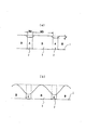
ローラの母材部1の表面に、耐磨耗性の低い部分Aと耐磨耗性の高い部分Bを交互に形成すると、図6(a)に示すように、耐磨耗性の低い部分A,A・・の各表面に安定的な凹みが形成され、破砕性が著しく向上する。耐磨耗性の低い部分Aに生じる凹みの深さdは0.5〜15mmが好適であり、耐磨耗性の低い部分Aの幅Waは、耐磨耗性の高い部分Bの幅Wbの1/10〜1/2が適当である。 When the portions A having low wear resistance and the portions B having high wear resistance are alternately formed on the surface of the base material portion 1 of the roller, as shown in FIG. 6A, the portions having low wear resistance are formed. A stable dent is formed on each surface of A, A ..., and the friability is remarkably improved. The depth d of the dent generated in the portion A having low wear resistance is preferably 0.5 to 15 mm, and the width Wa of the portion A having low wear resistance is the width Wb of the portion B having high wear resistance. 1/10 to 1/2 of is suitable.
この破砕面部材とは別に、本出願人は、マンガンを主な合金成分とするマンガンオーステナイト系合金をマトリックスとして、そのマトリクス中に、別途製造された高硬度炭化物粒子を、断面積比で20〜70%占めるよう添加して分散混合させた複合材を先に開発した(特許文献2) Apart from this crushing surface member, the present applicant uses a manganese austenitic alloy containing manganese as a main alloy component as a matrix, and separately produces high-hardness carbide particles in the matrix at a cross-sectional area ratio of 20 to The composite material added and dispersed and mixed so as to occupy 70% was first developed (Patent Document 2).
この複合材は、高面圧下で耐磨耗性に著しく優れるので、耐磨耗性の高い部分Bを形成するための耐磨耗性肉盛材としても好適である。マトリックスとしては、重量%でC:0.2〜1.8%、Cr:25%以下、Mn:11〜25%以下、Ni:10%以下、Si:2.5%以下、Nb:0〜10%を含む、マンガンオーステナイト系合金が特に好ましい。 Since this composite material is remarkably excellent in wear resistance under high surface pressure, it is also suitable as a wear-resistant build-up material for forming the portion B having high wear resistance. As the matrix, C: 0.2 to 1.8% by weight, Cr: 25% or less, Mn: 11 to 25% or less, Ni: 10% or less, Si: 2.5% or less, Nb: 0 to 0 Manganese austenitic alloys containing 10% are particularly preferred.
耐磨耗性の高い部分B,B・・をこの複合材で形成すると、耐磨耗性の高い部分Bの耐磨耗性が余りにも高くなるために、耐磨耗性の低い部分Aと耐磨耗性の高い部分Bとの耐磨耗性の差異が圧倒的に異なり、その結果として、図6(b)に示すように、耐磨耗性の低い部分Aが早期磨耗するようになる。 If parts B, B,... With high wear resistance are formed from this composite material, the wear resistance of part B with high wear resistance is too high. As shown in FIG. 6 (b), the difference in wear resistance between the portion B having high wear resistance is overwhelmingly different, and as a result, the portion A having low wear resistance is worn early. Become.
耐磨耗性の低い部分Aが余りに早く磨耗すると、耐磨耗性の高い部分Bの両側面が極端な磨耗に曝され、両側のエッジ部が欠落し損耗が進行することにより、耐磨耗性の高い部分Bが尖った山形になる。その結果、耐磨耗性の高い部分Bの見掛け上の幅が極端に小さくなり、また、耐磨耗性の低い部分Aに生じる凹みの深さも極端に深くなる。その結果、騒音が大きくなるとか、耐磨耗性の高い部分Bに欠けが発生して寿命が短くなるなどの問題が発生する。 If the part A with low wear resistance wears too quickly, both sides of the part B with high wear resistance are exposed to extreme wear, and the edges on both sides are lost and wear progresses, resulting in wear resistance. The highly probable portion B has a sharp mountain shape. As a result, the apparent width of the portion B with high wear resistance becomes extremely small, and the depth of the dent generated in the portion A with low wear resistance becomes extremely deep. As a result, problems such as increased noise and chipping in the highly wear-resistant portion B, resulting in shortened lifespan, and the like occur.
このような耐磨耗性の低い部分Aの早期磨耗は、粒径が2〜3mm程度の細粒材料、例えば粘土、ケイ石等を粉砕する場合は、耐磨耗性の低い部分Aに生じた凹みに微粉が埋まり、一定以上の磨耗進展が防止されるため、顕著化しない。しかし、セメント工場における原料ミルローラによる粘土、ケイ石の粉砕のように粒径が50〜60mmの粗粒を粉砕する場合は、この早期磨耗が顕著化する。 Such early wear of the portion A having low wear resistance occurs in the portion A having low wear resistance when pulverizing a fine-grained material having a particle diameter of about 2 to 3 mm, such as clay or silica. Since the fine powder is buried in the dent and the wear progress beyond a certain level is prevented, it does not become noticeable. However, in the case of pulverizing coarse particles having a particle diameter of 50 to 60 mm, such as pulverization of clay and silica using a raw material mill roller in a cement factory, this early wear becomes prominent.
耐磨耗性の高い部分Bの耐磨耗性を顕著に引き上げた場合に問題となる耐磨耗性の低い部分Aの早期磨耗を防止するための対策として、本出願人は、耐磨耗性の低い部分Aの上に、耐磨耗性の高い部分Bと同等かそれ以下の耐磨耗性をもち、耐磨耗性の低い部分Aよりかは耐磨耗性が高い耐磨耗性金属を肉盛する方法を先に提案した(特許文献3)。 As a measure for preventing the early wear of the portion A having low wear resistance, which becomes a problem when the wear resistance of the portion B having high wear resistance is remarkably increased, the present applicant Wear resistance equal to or less than high wear resistance part B on the low wear resistance part A, and higher wear resistance than low wear resistance part A Previously, a method for overlaying a conductive metal was proposed (Patent Document 3).
この対策によると、耐磨耗性の低い部分Aの上に肉盛された耐磨耗性金属は、耐磨耗性の高い部分Bとの耐磨耗性の差を小さくし、耐磨耗性の低い部分Aの早期磨耗を防止することかできる。耐磨耗性の高い部分Bと同等の耐磨耗性金属を肉盛しても、その肉盛金属は溶け込みに伴う希釈により耐磨耗性の高い部分Bより耐磨耗性が劣り、凹みの発生を阻害することにはならない。 According to this measure, the wear-resistant metal built up on the portion A having low wear resistance reduces the difference in wear resistance from the portion B having high wear resistance and wear resistance. It is possible to prevent the early wear of the portion A having low properties. Even if the wear-resistant metal equivalent to that of the part B with high wear resistance is built up, the build-up metal is inferior in wear resistance to the part B with high wear resistance due to dilution due to penetration, and the dent. It does not inhibit the occurrence of.
耐磨耗性の低い部分Aの上に肉盛された耐磨耗性金属の厚みは最低でも3mmは必要であり、厚いほど好ましい。この肉盛厚さが小さいと、耐磨耗性の低い部分Aが早期に露出し、耐磨耗性金属を肉盛する意味が薄れる。この観点から、耐磨耗性の低い部分Aの全体を耐磨耗性金属の肉盛層に置換することも推奨される。しかし、耐磨耗性金属の肉盛層を厚くすることは技術的、コスト的に難しく、性能的にも問題がある。 The thickness of the wear-resistant metal deposited on the portion A having low wear resistance needs to be at least 3 mm. If the build-up thickness is small, the portion A having low wear resistance is exposed early, and the meaning of building up the wear-resistant metal is diminished. From this point of view, it is also recommended to replace the entire portion A having low wear resistance with a build-up layer of wear-resistant metal. However, it is technically and costly difficult to increase the build-up layer of wear-resistant metal, and there is a problem in performance.
すなわち、3mm程度の肉盛層であれは1層溶接ですみ、技術的、コスト的な制約は殆どない。しかし、肉盛層が厚くなり、例えば高さ30mmの仕切りリブの全体を耐磨耗性金属の肉盛層に置換するとなると、ローラの母材部上に30mmの高さのリブ状に肉盛を行う必要がある。この肉盛では、2枚の銅板を所定間隔をあけて母材部上に立て、その間に多層肉盛溶接を行うが、層数が多くなり、施工時間が極端に長くなる上に、ローラの母材部は湾曲しているため、技術的にも難しい。加えて、耐磨耗性の低い部分Aの全体を耐磨耗性金属で形成した場合、靱性に優れている耐磨耗性金属と言えども、母材部や仕切りリブに使用されるSS400などの構造材料に比べて延性に劣り、破砕作業途中で、耐磨耗性の高い部分と共に剥離脱落する危険性がある。 That is, if the overlay layer is about 3 mm, only one layer welding is required, and there are almost no technical and cost restrictions. However, when the build-up layer becomes thicker, for example, when the entire partition rib having a height of 30 mm is replaced with a build-up layer of wear-resistant metal, the build-up is performed in a rib shape with a height of 30 mm on the base material portion of the roller. Need to do. In this build-up, two copper plates are placed on the base metal part at a predetermined interval, and multilayer build-up welding is performed between them, but the number of layers increases, the construction time becomes extremely long, and the roller Since the base material is curved, it is technically difficult. In addition, when the entire portion A having low wear resistance is formed of a wear resistant metal, although it is a wear resistant metal having excellent toughness, SS400 used for the base material part and the partition rib, etc. It is inferior to ductility in comparison with the structural material, and there is a risk of peeling and dropping together with a highly wear-resistant part during the crushing operation.
ちなみに、ローラの母材部及び仕切りリブとしては、全体の機械的強度を確保するためにSS400、ステンレス鋼、S35C炭素鋼のような耐磨耗性の低い材料の使用が不可欠である。 Incidentally, it is indispensable to use a material with low wear resistance such as SS400, stainless steel, and S35C carbon steel for the base material portion and the partition rib of the roller in order to ensure the overall mechanical strength.
本発明の目的は、耐磨耗性の高い部分の耐磨耗性を顕著に引き上げた場合に問題となる耐磨耗性の低い部分の早期磨耗を、耐磨耗性の低い部分の本来機能を損なうことなく防止することが可能な破砕面部材を提供することにある。 The object of the present invention is to prevent the early wear of the low wear-resistant part, which becomes a problem when the wear resistance of the high wear-resistant part is remarkably increased, and the original function of the low wear-resistant part. It is providing the crushing surface member which can prevent without impairing.
上記目的を達成するために、本発明の破砕面部材は、粉砕機に使用される破砕面部材であって、その破砕面部材の母材部の表面に、耐磨耗性の低いリブ状部分が所定ピッチで設けられると共に、隣接するリブ状部分の間に耐磨耗性の高い材料が充填されており、前記リブ状部分には、当該リブ状部分を厚み方向に貫通し耐磨耗性がリブ状部分の耐磨耗性より高く耐磨耗性の高い材料と同等かそれ以下である複数の磨耗抑制チップが、前記リブ状部分の長手方向に所定間隔で埋設されていることを特徴とする。 In order to achieve the above object, the crushing surface member of the present invention is a crushing surface member used in a crusher, and a rib-like portion having low wear resistance on the surface of the base material portion of the crushing surface member. Are provided at a predetermined pitch, and a material having high wear resistance is filled between the adjacent rib-shaped portions, and the rib-shaped portions penetrate through the rib-shaped portions in the thickness direction and wear resistance. A plurality of wear suppression tips that are higher than the wear resistance of the rib-like portion and equal to or less than the wear-resistant material are embedded at predetermined intervals in the longitudinal direction of the rib-like portion. And
本発明の破砕面部材においては、耐磨耗性の低いリブ状部分がある程度磨耗すると、当該リブ状部分に埋設された複数の磨耗抑制チップが露出する。そうなると、耐磨耗性の低いリブ状部分の磨耗が抑制され、その結果として、耐磨耗性の低いリブ状部分の早期磨耗が抑制される。耐磨耗性の低いリブ状部分の材質を変更する必要がないので、その本来機能を損なう危険性がない。 In the crushing surface member of the present invention, when a rib-like portion having low wear resistance is worn to some extent, a plurality of wear-suppressing tips embedded in the rib-like portion are exposed. If it becomes so, abrasion of the rib-like part with low wear resistance is suppressed, and as a result, early wear of the rib-like part with low wear resistance is suppressed. Since there is no need to change the material of the rib-like portion with low wear resistance, there is no risk of impairing its original function.
リブ状部分を厚み方向に貫通する複数の磨耗抑制チップは、リブ状部分の両側に充填された耐磨耗性の高い材料と溶融一体化した構成が好ましい。この構成により、磨耗抑制チップの脱落が防止される。 It is preferable that the plurality of wear suppressing tips penetrating the rib-shaped portion in the thickness direction are fused and integrated with a highly wear-resistant material filled on both sides of the rib-shaped portion. With this configuration, the wear-inhibiting tip is prevented from falling off.
磨耗抑制チップの材質としては、コバルト結合剤により焼結された炭化タングステンの超硬合金(焼結体)が好ましい。この材質は、リブ状部分の両側に充填された耐磨耗性の高い材料と溶融一体化した場合の耐割れ性に優れる。 As a material of the wear suppression chip, a tungsten carbide cemented carbide (sintered body) sintered with a cobalt binder is preferable. This material is excellent in crack resistance when fused and integrated with a highly wear-resistant material filled on both sides of the rib-like portion.
耐磨耗性の高い材料としては、高クロム鋳鉄系合金、炭化物析出型合金、ニッケル基合金マトリックス又はコバルト基合金マトリックスにタングステン炭化物粒子を20〜65%分散混合させた複合材などを用いることができる。特に好ましい材料は、マンガンを主な合金成分とするマンガンオーステナイト系合金からなるマトリックス中に、別途製造された高硬度炭化物粒子を、断面積比で20〜70%占めるよう添加して分散混合させた複合材である。マトリックスとしてのマンガンオーステナイト系合金は、重量%でC:0.2〜1.8%、Cr:25%以下、Mn:11〜25%以下、Ni:10%以下、Si:2.5%以下、Nb:0〜10%を含むものが好ましい。この複合材は特に高い耐磨耗性を付与することができる。 As a material having high wear resistance, a high chromium cast iron alloy, a carbide precipitation alloy, a composite material in which tungsten carbide particles are dispersed and mixed in a nickel base alloy matrix or a cobalt base alloy matrix in an amount of 20 to 65% is used. it can. A particularly preferable material was dispersed and mixed by adding separately produced high-hardness carbide particles to a matrix area of 20 to 70% in a matrix made of a manganese austenitic alloy containing manganese as a main alloy component. It is a composite material. Manganese austenitic alloy as a matrix is C: 0.2-1.8%, Cr: 25% or less, Mn: 11-25% or less, Ni: 10% or less, Si: 2.5% or less by weight%. , Nb: 0 to 10% is preferable. This composite material can impart particularly high wear resistance.
これらの材料は、例えば多層肉盛溶接により、隣接するリブ状部分の間に充填することができる。 These materials can be filled between adjacent rib portions by, for example, multi-layer overlay welding.
本発明の破砕面部材は、耐磨耗性の低いリブ状部分に、当該リブ状部分を厚み方向に貫通し耐磨耗性がリブ状部分の耐磨耗性より高く耐磨耗性の高い材料と同等かそれ以下である複数の磨耗抑制チップを、リブ状部分の長手方向に所定間隔で埋設したことにより、耐磨耗性の高い部分の耐磨耗性を顕著に引き上げた場合に問題となる耐磨耗性の低い部分の早期磨耗を、耐磨耗性の低い部分の本来機能を損なうことなく防止することができ、寿命延長に特に大きな効果を発揮する。 The crushing surface member of the present invention penetrates through the rib-shaped portion in the thickness direction to the rib-shaped portion having low wear resistance, and the wear resistance is higher than the wear resistance of the rib-shaped portion and has high wear resistance. There is a problem when the wear resistance of parts with high wear resistance is remarkably increased by embedding multiple wear suppression tips that are equal to or less than the material at predetermined intervals in the longitudinal direction of the rib-shaped part. Therefore, it is possible to prevent the early wear of the portion with low wear resistance without impairing the original function of the portion with low wear resistance.
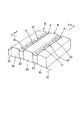
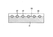
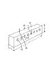
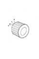
以下に本発明の実施形態を図面に基づいて説明する。図1は本発明の一実施形態を示す破砕面部材の主要部を示す斜視図、図2は図1中のX線矢示図、図3は図1中のY線矢示図、図4は同破砕面部材に使用されているリブ状部分の斜視図である。 Embodiments of the present invention will be described below with reference to the drawings. 1 is a perspective view showing a main part of a crushing surface member according to an embodiment of the present invention, FIG. 2 is an X-ray arrow diagram in FIG. 1, FIG. 3 is a Y-line arrow diagram in FIG. FIG. 3 is a perspective view of a rib-like portion used for the crushing surface member.
本実施形態の破砕面部材は粉砕機に使用される粉砕ローラである。この粉砕ローラは、ローラ本体10の外周面上に、耐磨耗性の低い部分Aと耐磨耗性の高い部分Bとを交互に形成した構成になっている。耐磨耗性の低い部分Aは、例えばSS400からなる厚さTが9mm、高さHが30mmのフラットバー21をローラ本体10の外周面に周方向に所定間隔で溶接してリブ状部分20とすることにより形成されている。
The crushing surface member of this embodiment is a crushing roller used in a crusher. This pulverizing roller has a configuration in which portions A having low wear resistance and portions B having high wear resistance are alternately formed on the outer peripheral surface of the
リブ状部分20の本体部であるフラットバー21には、厚さ方向に貫通する複数の磨耗抑制チップ22が長さ方向(L方向)に所定間隔で埋設されている。複数の磨耗抑制チップ22は、ここでは炭化タングステンの焼結体、より具体的にはコバルト結合剤により焼結された炭化タングステンの超硬合金からなる棒体(ここでは丸棒)であり、その棒体を前記フラットバー21に予め形成した貫通孔に嵌め込むことにより、フラットバー21中に埋設されている。磨耗抑制チップ30の両端部は、フラットバー21の両表面から若干突出している。
A plurality of
耐磨耗性の高い部分Bは、隣接するフラットバー21,21間に前述した複合材、すなわちマンガンを主な合金成分とするマンガンオーステナイト系合金からなるマトリックス中に、別途製造された高硬度炭化物粒子を、断面積比で20〜70%占めるよう添加して分散混合させた複合材を、フラットバー21,21とほぼ同じ高さまで多層肉盛溶接することにより形成されている。この高耐磨耗性の肉盛硬化金属30は、ローラ周方向両側のフラットバー21,21及び下側のローラ本体10に溶け込むと共に、各フラットバー21に埋設された複数の磨耗抑制チップ22と溶融一体化している。
The part B having high wear resistance is a high-hardness carbide manufactured separately in the above-described composite material between the
磨耗抑制チップ22の両端部をフラットバー21の両表面から突出させたのは、肉盛硬化金属30との溶融一体化を促進するためであり、この肉盛硬化金属30との溶融一体化により、フラットバー21中の複数の磨耗抑制チップ22は、両側の肉盛硬化金属30,30にも保持され、より強固に固定されることになる。磨耗抑制チップ22の両端部の突出量は1〜3mmが好ましい。この突出量が少なすぎると肉盛硬化金属30との溶融一体化による保持効果が不足し、多すぎる場合は肉盛硬化金属30に溶融してマトリックスに溶け込みマトリックス延性を阻害する。
The reason why both ends of the
また、磨耗抑制チップ22に関して、その太さは丸棒の場合の直径Dで表して4〜10mmが好ましい。磨耗抑制チップ22が細すぎる場合は、肉盛硬化金属30を形成するときの溶融により消失する危険性が生じる。また所定の耐磨耗性を確保する必要上、磨耗抑制チップ22の配設間隔Pがつまり、その個数が多くなることから製作コストが嵩むようになる。反対に磨耗抑制チップ22が太すぎる場合は、肉盛硬化金属30との溶融一体化が進まず、肉盛硬化金属30による十分なチップ保持効果が得られない。
The thickness of the
磨耗抑制チップ22の配設間隔Pについては、磨耗抑制チップ22の直径Dに対する比率で表して2D以上、4D以下が望ましい。配設間隔Pが小さすぎる場合はリブ状部分20の磨耗が減少して当初の目的である噛み込み効果が減少する。反対にこれが大きすぎる場合はリブ状部分20の早期磨耗を抑制する効果が減少する。またフラットバー21の早期磨耗により、磨耗抑制チップ22がフラットバー21から浮き上がった状態になり、分離脱落の危険性が増大する。
About the arrangement | positioning space | interval P of the wear suppression chip |
磨耗抑制チップ22は、ここでは1列1段に設けられているが、複数段に設けることもでき、その場合は各段で前記配設間隔Pを満足させることが望ましい。リブ状部分20の高さが高い場合、磨耗抑制チップ22を複数段に設けることは有効であり、その場合は上段におけるチップ間に下段におけるチップが位置するいわゆる千鳥状に配置するのが、磨耗抑制効果を効果的に引き出せる点から望ましい。
Here, the
磨耗抑制チップ22の配設位置については、リブ状部分20の表面から磨耗抑制チップ22の表面側端部までの距離Sで表して0〜5mmが望ましい。この距離が大きすぎると、フラットバー21が磨耗し磨耗抑制チップ22が露出した段階で既にリブ状部分20に大きな凹みが生じ、肉盛硬化金属30が過度に露出することから、肉盛硬化金属30のエッジ欠けやこれによる噛み込み性の低下が生じ、磨耗抑制チップ22による早期磨耗抑制効果が低減する。この磨耗抑制チップ22は使用開始前から一部がリブ状部分20の表面に露出していてもよい。その場合もリブ状部分20の長さ方向で隣接する磨耗抑制チップ22,22間が凹み、凹みによる噛み込み性の向上といったリブ状部分20の本来機能は得られる。
About the arrangement | positioning position of the wear suppression chip |
磨耗抑制チップ22の構成材料である炭化タングステンの焼結体、より具体的にはコバルト結合剤により焼結された炭化タングステンの超硬合金に関しては、コバルト含有量が高いほど肉盛硬化金属30との融着性能は向上する反面、超硬合金自体の硬度は低下し、耐磨耗性の低下を招く。この観点から超硬合金の硬度はHv850〜1200の範囲内が好ましく、コバルト含有量については超硬合金の硬度を維持できる範囲内であれば融着性の観点からその含有はむしろ好ましく、最小15重量%から最大30重量%までの範囲内で許容される。
Regarding the sintered body of tungsten carbide that is a constituent material of the
本実施形態の破砕面部材(粉砕ローラ)においては、ローラ本体10の外周面上に、耐磨耗性の低い部分Aと耐磨耗性の高い部分Bとが交互に形成されている。耐磨耗性の低い部分Aは、フラットバー21により形成されたリブ状部分20であり、そのフラットバー21には、厚さ方向に貫通する複数本の棒状の磨耗抑制チップ22が長さ方向(L方向)に所定間隔で埋設されている。
In the crushing surface member (crushing roller) of this embodiment, portions A having low wear resistance and portions B having high wear resistance are alternately formed on the outer peripheral surface of the
この破砕面部材が粉砕に使用されると、耐磨耗性の低い部分Aであるリブ状部分20の表面が優先的に磨耗し、凹みができる。これにより噛み込み性などが向上し、破砕性能が上がる。リブ状部分20の本体部は軟鋼製のフラットバー21であり、破砕面部材の本体部であるローラ本体10との接合性が良好である。その一方で、フラットバー21の磨耗は急速に進む。
When this crushing surface member is used for pulverization, the surface of the rib-shaped
しかるに、本実施形態ではフラットバー21の長さ方向に所定間隔で、複数本の棒状の磨耗抑制チップ22が埋設されている。フラットバー21の磨耗が進み、適正な凹みが形成されると、磨耗抑制チップ22が露出し、これ以降のフラットバー21の磨耗が抑制される。この結果、耐磨耗性の高い部分Bである肉盛硬化金属30の過度の露出が阻止され、そのエッジ部の欠落等が防止されることにより、適正な形状及び深さの凹みが維持される。
However, in this embodiment, a plurality of rod-shaped
また、磨耗抑制チップ22の両端部が両側の肉盛硬化金属30、30と溶融一体化しているために、磨耗抑制チップ22がフラットバー21だけでなく、両側の肉盛硬化金属30、30によっても効果的に保持される。その結果、磨耗抑制チップ22の脱落も効果的に防止される。
Further, since both end portions of the
10 ローラ本体(母材部)
20 リブ状部分
21 フラットバー
22 磨耗抑制チップ
30 肉盛硬化金属
A 耐磨耗性の低い部分
B 耐磨耗性の高い部分
10 Roller body (base material)
20 Rib-shaped
Claims (4)
Priority Applications (1)
| Application Number | Priority Date | Filing Date | Title |
|---|---|---|---|
| JP2005108702A JP4579035B2 (en) | 2005-04-05 | 2005-04-05 | Crushing surface member |
Applications Claiming Priority (1)
| Application Number | Priority Date | Filing Date | Title |
|---|---|---|---|
| JP2005108702A JP4579035B2 (en) | 2005-04-05 | 2005-04-05 | Crushing surface member |
Publications (2)
| Publication Number | Publication Date |
|---|---|
| JP2006281179A true JP2006281179A (en) | 2006-10-19 |
| JP4579035B2 JP4579035B2 (en) | 2010-11-10 |
Family
ID=37403631
Family Applications (1)
| Application Number | Title | Priority Date | Filing Date |
|---|---|---|---|
| JP2005108702A Expired - Lifetime JP4579035B2 (en) | 2005-04-05 | 2005-04-05 | Crushing surface member |
Country Status (1)
| Country | Link |
|---|---|
| JP (1) | JP4579035B2 (en) |
Cited By (4)
| Publication number | Priority date | Publication date | Assignee | Title |
|---|---|---|---|---|
| WO2013046422A1 (en) * | 2011-09-30 | 2013-04-04 | 三菱重工業株式会社 | Biomass crushing device, and system for mixed combustion of biomass and coal |
| JP2014014748A (en) * | 2012-07-06 | 2014-01-30 | Ing Shoji Kk | Grinding surface member |
| CN114939472A (en) * | 2022-05-23 | 2022-08-26 | 郑州机械研究所有限公司 | Wear-resistant structure |
| CN114939471A (en) * | 2022-05-23 | 2022-08-26 | 郑州机械研究所有限公司 | Wear-resistant structure |
Citations (6)
| Publication number | Priority date | Publication date | Assignee | Title |
|---|---|---|---|---|
| JPS62164937U (en) * | 1986-04-10 | 1987-10-20 | ||
| JPS63143946A (en) * | 1986-12-09 | 1988-06-16 | 株式会社山本製作所 | Rice-cleaning roll |
| JPS6428951U (en) * | 1987-08-11 | 1989-02-21 | ||
| JPH05317732A (en) * | 1992-05-19 | 1993-12-03 | Kawasaki Heavy Ind Ltd | Tooth plate of crusher |
| JPH09108887A (en) * | 1995-10-16 | 1997-04-28 | I N Ji Shoji Kk | Wear resistant material |
| JP2001347175A (en) * | 2000-06-08 | 2001-12-18 | Ing Shoji Kk | Crushing surface member used for crusher |
-
2005
- 2005-04-05 JP JP2005108702A patent/JP4579035B2/en not_active Expired - Lifetime
Patent Citations (6)
| Publication number | Priority date | Publication date | Assignee | Title |
|---|---|---|---|---|
| JPS62164937U (en) * | 1986-04-10 | 1987-10-20 | ||
| JPS63143946A (en) * | 1986-12-09 | 1988-06-16 | 株式会社山本製作所 | Rice-cleaning roll |
| JPS6428951U (en) * | 1987-08-11 | 1989-02-21 | ||
| JPH05317732A (en) * | 1992-05-19 | 1993-12-03 | Kawasaki Heavy Ind Ltd | Tooth plate of crusher |
| JPH09108887A (en) * | 1995-10-16 | 1997-04-28 | I N Ji Shoji Kk | Wear resistant material |
| JP2001347175A (en) * | 2000-06-08 | 2001-12-18 | Ing Shoji Kk | Crushing surface member used for crusher |
Cited By (4)
| Publication number | Priority date | Publication date | Assignee | Title |
|---|---|---|---|---|
| WO2013046422A1 (en) * | 2011-09-30 | 2013-04-04 | 三菱重工業株式会社 | Biomass crushing device, and system for mixed combustion of biomass and coal |
| JP2014014748A (en) * | 2012-07-06 | 2014-01-30 | Ing Shoji Kk | Grinding surface member |
| CN114939472A (en) * | 2022-05-23 | 2022-08-26 | 郑州机械研究所有限公司 | Wear-resistant structure |
| CN114939471A (en) * | 2022-05-23 | 2022-08-26 | 郑州机械研究所有限公司 | Wear-resistant structure |
Also Published As
| Publication number | Publication date |
|---|---|
| JP4579035B2 (en) | 2010-11-10 |
Similar Documents
| Publication | Publication Date | Title |
|---|---|---|
| CN100358670C (en) | Fusion structure and method for hard alloy and diamond piece, drilling tool and cutting piece thereof | |
| CN102962114B (en) | Manufacturing method of breaking hammerhead | |
| US5324098A (en) | Cutting tool having hard tip with lobes | |
| CA2585688C (en) | Wear-resistant castings and method of fabrication thereof | |
| US20130052481A1 (en) | Hard face structure and body comprising same | |
| JPS6011096B2 (en) | Composite made of sintered charcoal alloy and cast iron | |
| WO2008042330B1 (en) | Abrasive wear resistant hardfacing materials, drill bits and drilling tools including abrasive wear resistant hardfacing materials, and methods for applying abrasive wear resistant hardfacing materials to drill bits and drilling tools | |
| IE73665B1 (en) | Diamond rock tools for percussive and rotary crushing rock drilling | |
| JPH04231164A (en) | Manufacture for bimetal castings and abrasive resistant parts produced by said method | |
| JP3779529B2 (en) | Crushing surface member used in crusher | |
| RU2694861C1 (en) | Method of manufacturing workpiece for cutting tool and corresponding workpiece | |
| JP4579035B2 (en) | Crushing surface member | |
| JP6804143B2 (en) | Earth and sand wear resistant parts and their manufacturing methods | |
| JP4148390B2 (en) | Abrasion resistant plate | |
| EP2239058A2 (en) | Wear-resistant roll and method of making it | |
| JP4696795B2 (en) | Welding material for overlaying, excavation tool hardened using the same, and plate for wear prevention | |
| JP7335959B2 (en) | DISC CUTTER FOR TUNNEL BORING MACHINE AND METHOD FOR MANUFACTURING THE SAME | |
| CN101200998B (en) | Bonding structure and bonding method for cemented carbide element and diamond element, cutting tip and cutting element for drilling tool, and drilling tool | |
| CN106522940A (en) | Abrasion-resistant tool bit | |
| JP2019203343A (en) | Cutting bit | |
| US9103004B2 (en) | Hardfacing composition and article having hardfacing deposit | |
| WO2014205514A1 (en) | Wear resistant stud | |
| JP5110659B2 (en) | Vertical mill and method for regenerating the same | |
| JP4579668B2 (en) | Sieving machine | |
| US20080236333A1 (en) | Hardfacing Composition And Article Having Hardfacing Deposit |
Legal Events
| Date | Code | Title | Description |
|---|---|---|---|
| A621 | Written request for application examination |
Free format text: JAPANESE INTERMEDIATE CODE: A621 Effective date: 20080404 |
|
| TRDD | Decision of grant or rejection written | ||
| A977 | Report on retrieval |
Free format text: JAPANESE INTERMEDIATE CODE: A971007 Effective date: 20100812 |
|
| A01 | Written decision to grant a patent or to grant a registration (utility model) |
Free format text: JAPANESE INTERMEDIATE CODE: A01 Effective date: 20100817 |
|
| A01 | Written decision to grant a patent or to grant a registration (utility model) |
Free format text: JAPANESE INTERMEDIATE CODE: A01 |
|
| A61 | First payment of annual fees (during grant procedure) |
Free format text: JAPANESE INTERMEDIATE CODE: A61 Effective date: 20100825 |
|
| FPAY | Renewal fee payment (event date is renewal date of database) |
Free format text: PAYMENT UNTIL: 20130903 Year of fee payment: 3 |
|
| R150 | Certificate of patent or registration of utility model |
Ref document number: 4579035 Country of ref document: JP Free format text: JAPANESE INTERMEDIATE CODE: R150 Free format text: JAPANESE INTERMEDIATE CODE: R150 |
|
| R250 | Receipt of annual fees |
Free format text: JAPANESE INTERMEDIATE CODE: R250 |
|
| R250 | Receipt of annual fees |
Free format text: JAPANESE INTERMEDIATE CODE: R250 |
|
| R250 | Receipt of annual fees |
Free format text: JAPANESE INTERMEDIATE CODE: R250 |
|
| R250 | Receipt of annual fees |
Free format text: JAPANESE INTERMEDIATE CODE: R250 |
|
| R250 | Receipt of annual fees |
Free format text: JAPANESE INTERMEDIATE CODE: R250 |
|
| R250 | Receipt of annual fees |
Free format text: JAPANESE INTERMEDIATE CODE: R250 |
|
| R250 | Receipt of annual fees |
Free format text: JAPANESE INTERMEDIATE CODE: R250 |
|
| R250 | Receipt of annual fees |
Free format text: JAPANESE INTERMEDIATE CODE: R250 |
|
| R250 | Receipt of annual fees |
Free format text: JAPANESE INTERMEDIATE CODE: R250 |
|
| R250 | Receipt of annual fees |
Free format text: JAPANESE INTERMEDIATE CODE: R250 |
|
| R250 | Receipt of annual fees |
Free format text: JAPANESE INTERMEDIATE CODE: R250 |
|
| R250 | Receipt of annual fees |
Free format text: JAPANESE INTERMEDIATE CODE: R250 |
|
| EXPY | Cancellation because of completion of term |