EP2239430A2 - Ölaufbewahrungsstruktur für einen Motor - Google Patents
Ölaufbewahrungsstruktur für einen Motor Download PDFInfo
- Publication number
- EP2239430A2 EP2239430A2 EP10250433A EP10250433A EP2239430A2 EP 2239430 A2 EP2239430 A2 EP 2239430A2 EP 10250433 A EP10250433 A EP 10250433A EP 10250433 A EP10250433 A EP 10250433A EP 2239430 A2 EP2239430 A2 EP 2239430A2
- Authority
- EP
- European Patent Office
- Prior art keywords
- crankcase
- oil storage
- oil
- storage chamber
- engine
- Prior art date
- Legal status (The legal status is an assumption and is not a legal conclusion. Google has not performed a legal analysis and makes no representation as to the accuracy of the status listed.)
- Granted
Links
- 230000005540 biological transmission Effects 0.000 claims abstract description 29
- 238000005192 partition Methods 0.000 claims abstract description 18
- 230000002000 scavenging effect Effects 0.000 claims description 20
- 239000000446 fuel Substances 0.000 description 4
- 238000002485 combustion reaction Methods 0.000 description 3
- 229910000831 Steel Inorganic materials 0.000 description 2
- 230000005587 bubbling Effects 0.000 description 2
- 230000015556 catabolic process Effects 0.000 description 2
- 239000003054 catalyst Substances 0.000 description 2
- 238000006731 degradation reaction Methods 0.000 description 2
- 239000002828 fuel tank Substances 0.000 description 2
- 238000002347 injection Methods 0.000 description 2
- 239000007924 injection Substances 0.000 description 2
- 239000010959 steel Substances 0.000 description 2
- 239000000498 cooling water Substances 0.000 description 1
- 230000000694 effects Effects 0.000 description 1
- 239000012212 insulator Substances 0.000 description 1
- 230000001050 lubricating effect Effects 0.000 description 1
- 238000000926 separation method Methods 0.000 description 1
- XLYOFNOQVPJJNP-UHFFFAOYSA-N water Substances O XLYOFNOQVPJJNP-UHFFFAOYSA-N 0.000 description 1
Images


Classifications
-
- F—MECHANICAL ENGINEERING; LIGHTING; HEATING; WEAPONS; BLASTING
- F01—MACHINES OR ENGINES IN GENERAL; ENGINE PLANTS IN GENERAL; STEAM ENGINES
- F01M—LUBRICATING OF MACHINES OR ENGINES IN GENERAL; LUBRICATING INTERNAL COMBUSTION ENGINES; CRANKCASE VENTILATING
- F01M11/00—Component parts, details or accessories, not provided for in, or of interest apart from, groups F01M1/00 - F01M9/00
- F01M11/0004—Oilsumps
-
- F—MECHANICAL ENGINEERING; LIGHTING; HEATING; WEAPONS; BLASTING
- F02—COMBUSTION ENGINES; HOT-GAS OR COMBUSTION-PRODUCT ENGINE PLANTS
- F02F—CYLINDERS, PISTONS OR CASINGS, FOR COMBUSTION ENGINES; ARRANGEMENTS OF SEALINGS IN COMBUSTION ENGINES
- F02F7/00—Casings, e.g. crankcases
- F02F7/0021—Construction
- F02F7/0039—Casings for small engines, especially with crankcase pumps
-
- F—MECHANICAL ENGINEERING; LIGHTING; HEATING; WEAPONS; BLASTING
- F16—ENGINEERING ELEMENTS AND UNITS; GENERAL MEASURES FOR PRODUCING AND MAINTAINING EFFECTIVE FUNCTIONING OF MACHINES OR INSTALLATIONS; THERMAL INSULATION IN GENERAL
- F16H—GEARING
- F16H57/00—General details of gearing
- F16H57/02—Gearboxes; Mounting gearing therein
- F16H57/029—Gearboxes; Mounting gearing therein characterised by means for sealing the gearboxes, e.g. to improve airtightness
-
- F—MECHANICAL ENGINEERING; LIGHTING; HEATING; WEAPONS; BLASTING
- F16—ENGINEERING ELEMENTS AND UNITS; GENERAL MEASURES FOR PRODUCING AND MAINTAINING EFFECTIVE FUNCTIONING OF MACHINES OR INSTALLATIONS; THERMAL INSULATION IN GENERAL
- F16H—GEARING
- F16H57/00—General details of gearing
- F16H57/02—Gearboxes; Mounting gearing therein
- F16H57/031—Gearboxes; Mounting gearing therein characterised by covers or lids for gearboxes
-
- F—MECHANICAL ENGINEERING; LIGHTING; HEATING; WEAPONS; BLASTING
- F16—ENGINEERING ELEMENTS AND UNITS; GENERAL MEASURES FOR PRODUCING AND MAINTAINING EFFECTIVE FUNCTIONING OF MACHINES OR INSTALLATIONS; THERMAL INSULATION IN GENERAL
- F16H—GEARING
- F16H57/00—General details of gearing
- F16H57/04—Features relating to lubrication or cooling or heating
-
- F—MECHANICAL ENGINEERING; LIGHTING; HEATING; WEAPONS; BLASTING
- F01—MACHINES OR ENGINES IN GENERAL; ENGINE PLANTS IN GENERAL; STEAM ENGINES
- F01M—LUBRICATING OF MACHINES OR ENGINES IN GENERAL; LUBRICATING INTERNAL COMBUSTION ENGINES; CRANKCASE VENTILATING
- F01M1/00—Pressure lubrication
- F01M1/12—Closed-circuit lubricating systems not provided for in groups F01M1/02 - F01M1/10
- F01M2001/123—Closed-circuit lubricating systems not provided for in groups F01M1/02 - F01M1/10 using two or more pumps
-
- F—MECHANICAL ENGINEERING; LIGHTING; HEATING; WEAPONS; BLASTING
- F01—MACHINES OR ENGINES IN GENERAL; ENGINE PLANTS IN GENERAL; STEAM ENGINES
- F01M—LUBRICATING OF MACHINES OR ENGINES IN GENERAL; LUBRICATING INTERNAL COMBUSTION ENGINES; CRANKCASE VENTILATING
- F01M11/00—Component parts, details or accessories, not provided for in, or of interest apart from, groups F01M1/00 - F01M9/00
- F01M11/0004—Oilsumps
- F01M2011/0037—Oilsumps with different oil compartments
-
- F—MECHANICAL ENGINEERING; LIGHTING; HEATING; WEAPONS; BLASTING
- F02—COMBUSTION ENGINES; HOT-GAS OR COMBUSTION-PRODUCT ENGINE PLANTS
- F02B—INTERNAL-COMBUSTION PISTON ENGINES; COMBUSTION ENGINES IN GENERAL
- F02B61/00—Adaptations of engines for driving vehicles or for driving propellers; Combinations of engines with gearing
- F02B61/02—Adaptations of engines for driving vehicles or for driving propellers; Combinations of engines with gearing for driving cycles
-
- F—MECHANICAL ENGINEERING; LIGHTING; HEATING; WEAPONS; BLASTING
- F16—ENGINEERING ELEMENTS AND UNITS; GENERAL MEASURES FOR PRODUCING AND MAINTAINING EFFECTIVE FUNCTIONING OF MACHINES OR INSTALLATIONS; THERMAL INSULATION IN GENERAL
- F16H—GEARING
- F16H57/00—General details of gearing
- F16H57/02—Gearboxes; Mounting gearing therein
- F16H2057/0203—Gearboxes; Mounting gearing therein the gearbox is associated or combined with a crank case of an engine
-
- F—MECHANICAL ENGINEERING; LIGHTING; HEATING; WEAPONS; BLASTING
- F16—ENGINEERING ELEMENTS AND UNITS; GENERAL MEASURES FOR PRODUCING AND MAINTAINING EFFECTIVE FUNCTIONING OF MACHINES OR INSTALLATIONS; THERMAL INSULATION IN GENERAL
- F16H—GEARING
- F16H57/00—General details of gearing
- F16H57/02—Gearboxes; Mounting gearing therein
- F16H2057/02039—Gearboxes for particular applications
- F16H2057/02043—Gearboxes for particular applications for vehicle transmissions
- F16H2057/02065—Gearboxes for particular applications for vehicle transmissions for motorcycles or squads
-
- F—MECHANICAL ENGINEERING; LIGHTING; HEATING; WEAPONS; BLASTING
- F16—ENGINEERING ELEMENTS AND UNITS; GENERAL MEASURES FOR PRODUCING AND MAINTAINING EFFECTIVE FUNCTIONING OF MACHINES OR INSTALLATIONS; THERMAL INSULATION IN GENERAL
- F16H—GEARING
- F16H57/00—General details of gearing
- F16H57/04—Features relating to lubrication or cooling or heating
- F16H57/0434—Features relating to lubrication or cooling or heating relating to lubrication supply, e.g. pumps; Pressure control
- F16H57/0441—Arrangements of pumps
-
- F—MECHANICAL ENGINEERING; LIGHTING; HEATING; WEAPONS; BLASTING
- F16—ENGINEERING ELEMENTS AND UNITS; GENERAL MEASURES FOR PRODUCING AND MAINTAINING EFFECTIVE FUNCTIONING OF MACHINES OR INSTALLATIONS; THERMAL INSULATION IN GENERAL
- F16H—GEARING
- F16H57/00—General details of gearing
- F16H57/04—Features relating to lubrication or cooling or heating
- F16H57/045—Lubricant storage reservoirs, e.g. reservoirs in addition to a gear sump for collecting lubricant in the upper part of a gear case
-
- F—MECHANICAL ENGINEERING; LIGHTING; HEATING; WEAPONS; BLASTING
- F16—ENGINEERING ELEMENTS AND UNITS; GENERAL MEASURES FOR PRODUCING AND MAINTAINING EFFECTIVE FUNCTIONING OF MACHINES OR INSTALLATIONS; THERMAL INSULATION IN GENERAL
- F16H—GEARING
- F16H57/00—General details of gearing
- F16H57/04—Features relating to lubrication or cooling or heating
- F16H57/048—Type of gearings to be lubricated, cooled or heated
- F16H57/0493—Gearings with spur or bevel gears
- F16H57/0494—Gearings with spur or bevel gears with variable gear ratio or for reversing rotary motion
Definitions
- the present invention relates to an oil storage structure for a small-sized vehicle engine, such as a motorcycle engine.
- a conventional engine is known (see, for example, Japanese Patent No. 2578284 (Fig. 8)) in which a crankshaft chamber is isolated from a transmission chamber, an oil pump (a scavenging pump) adapted to suck and supply under pressure the oil in the crankshaft chamber to the transmission chamber is provided, and oil is stored in an oil pan below the crankshaft chamber and in the transmission chamber communicating with the oil pan.
- the gears of the transmission mechanism do not dip into the oil. Therefore, the transmission chamber and the clutch chamber are allowed to communicate with each other so that oil is stored also in the clutch chamber.
- the height of the oil can be suppressed to a low level compared with the transmission chamber alone.
- an oil storage chamber for storing oil therein is formed so as to avoid the outer circumference of a clutch.
- the oil storage chamber is formed so as to avoid the clutch, it is necessary to form a vertically long oil storage chamber to allow an adequate amount of oil to be stored.
- the crankcase is split into right and left cases, one of the right and left cases and a clutch cover can constitute the oil storage chamber.
- the oil storage chamber will be formed by the upper and lower crankcases and the clutch cover. If the oil storage chamber is formed so as to straddle the three members as described above, there arises a problem in that it is difficult to ensure liquid-tight performance.
- the present invention at least in its preferred embodiments, provides an oil storage structure in which if it is applied to an engine provided with a vertically-split crankcase (that is, a crankcase split into an upper part and a lower part), a clutch mechanism does not dip into the oil so as not to affect clutch disengagement performance and liquid-tight performance can be ensured reliably.
- a vertically-split crankcase that is, a crankcase split into an upper part and a lower part
- an oil storage structure of an engine in which a crankcase rotatably supporting a crankshaft and a transmission shaft and forming at least a transmission chamber is provided, a clutch is provided on an end portion of the transmission shaft projecting laterally from the crankcase, and a crankcase cover is provided which is joined to the crankcase to form an oil storage chamber adapted to store oil therein, and is characterized in that : the crankcase is vertically split into an upper crankcase and a lower crankcase with the crankshaft put therebetween; the crankcase cover is formed with a partition wall extending along an outer circumference of the clutch mechanism as viewed from an direction of the transmission shaft; the partition wall divides a space between the crankcase and the crankcase cover into a plurality of chambers; of the plurality of chambers, a chamber which does not include a clutch device is used as the oil storage chamber; and an upper edge portion of the partition wall is at least partially disposed along the surface along which the crankcase is split so that the oil storage
- the partition wall extending along the outer circumference of the clutch mechanism splits the space between the crankcase and the crankcase cover into chambers, and the chamber which does not include the clutch mechanism is used as the oil storage chamber.
- the clutch mechanism does not dip into oil, the disengagement performance of the clutch can be ensured without affecting the clutch release performance.
- the oil storage chamber of the engine formed by the vertically split crankcase is formed only by the lower crankcase so as not to straddle the upper and lower crankcases, the amount of oil to be stored can be ensured at a maximum while ensuring liquid-tight performance.
- the partition wall extends along the outer circumference of the clutch mechanism, then extends along an outer circumference of a primary drive gear driven by the crankshaft to drive the clutch mechanism, and merges with the upper edge portion extending along a crankcase surface portion including the crankshaft, and the upper edge portion further merges with a front wall and a lower wall of the oil storage chamber, thus forming annularity, and consequently the oil storage chamber is formed as a closed chamber.
- the engine is provided with a balancer shaft below the crankshaft, a scavenging pump for supplying under pressure oil to the oil storage chamber is coaxially joined to an end portion of the balancer shaft and is driven, and the scavenging pump is incorporated in the oil storage chamber.
- a vacant space occurs on the end portion side of the balancer shaft axially shorter than the crankshaft and the transmission shaft.
- the vacant space is used to provide the oil storage chamber, in which the scavenging pump is incorporated.
- the scavenging pump is drivingly connected to the end portion of the balancer shaft and is driven by the balancer shaft.
- the oil storage chamber is not enlarged in the direction of the crankshaft for compact configuration.
- the pump drive mechanism can be simplified so that the overall engine can be downsized.
- a feed pump adapted to feed oil in the oil storage chamber to various portions of the engine is provided coaxially with the scavenging pump, and an oil filter connected to an oil passage located on an discharge side of the feed pump is provided at a front wall of the crankcase adjacently to the oil storage chamber.
- the oil storage chamber, the scavenging pump, the feed pump and the oil filter are collectively arranged in the front portion of the crankcase, and so the oil passage connecting them together can be shortened to provide the compact configuration.
- an oil suction pipe extending along a lowest portion of the oil storage chamber is connected to a suction side of the feed pump. This allows the oil collecting on the lowest portion of the oil storage chamber to be reliably sucked through the suction pipe.
- the engine 1 is a two-cylinder internal combustion engine and is supported by the main frames 82, the centre frames 83 and the down frames 84.
- the power of the engine 1 is transmitted to the rear wheel RW via a transmission built in the engine 1 and via a rear wheel drive chain 41.
- a fuel tank 91 is mounted on the left and right main frames 82 and centre frames 83 so as to be located above the engine 1.
- a tandem seat 92 for a driver and a pillion passenger is mounted on the seat stays 85.
- a throttle body 25 continuous with an intake port of the engine 1 is coupled to an air cleaner 93.
- a radiator 94 is disposed in front of the engine 1.
- An exhaust pipe 95 extending from a front surface of the engine 1 extends below the engine 1 and connects with a muffler 96 located at a vehicle body rear portion.
- a catalyst case 97 of the exhaust pipe 95 is provided at a position forward of the engine and houses a catalyst 98 therein.
- Fuel in the fuel tank 91 is supplied to an injector (fuel injection valve) 26 via a fuel pump 99 and then to the engine 1.
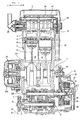
- Fig. 2 is a longitudinal cross-sectional view of the above-mentioned two-cylinder engine 1 as viewed from the right.
- Arrow F indicates the front of the engine 1 corresponding to the front of the vehicle encountered when the engine 1 is mounted on the vehicle.
- the engine 1 is a transmission-integral type engine. Its main shell includes a vertically split crankcase 2 composed of an upper crankcase 2A and a lower crankcase 2B, a cylinder block 3 formed integrally with the upper crankcase 2A, a cylinder head 4, a cylinder head cover 5, and an oil pan 6 made of a thin steel plate attached to a lower surface of the lower crankcase 2B.
- a crankshaft 7 and a counter shaft 10 of the constant-mesh type gear transmission 8 are disposed such that their centrelines lie generally on the division surface between the upper and lower crankcases 2A, 2B.
- a main shaft 9 of the transmission 8 is disposed below and between the above-mentioned shafts.
- a gear change mechanism 11 is disposed below the counter shaft 10 and rearward of the main shaft 9.
- An upper balancer 12A is disposed obliquely rearwardly of and above the crankshaft 7.
- a lower balancer 12B is disposed obliquely forwardly of and below the crankshaft 7 at a position symmetrical to the upper balancer 12A.
- the balancers 12A, 12B are directly driven by the crankshaft 7.
- An oil pump 13 is mounted to the shaft end of the lower balancer 12B. As described later, this oil pump 13 is composed of a scavenging pump 64 and a feed pump 65.
- the cylinder block 3 is provided with two cylinders 14.
- a piston 15 is slideably fitted into each of the cylinders 14.
- Intake valves 18, exhaust valves 19, a camshaft 20, and a rocker shaft 22 provided with rocker arms 21 are provided on the cylinder head 4.
- Respective intake passages 23 of the two cylinders 14 are assembled into a single one via an intake manifold portion 24 and connected to a single throttle body 25.
- the intake manifold portion 24 is equipped with two injectors (fuel injection valves) 26 for respective corresponding cylinders.
- the throttle body 25 is mounted to the intake manifold portion 24 via an insulator 33.
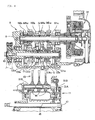
- Fig. 3 is a cross-sectional view taken along line III-III of Fig. 2 , and is also a horizontal-surface development view of the engine 1 including the camshaft 20, the cylinders 14, the crankshaft 7, the main shaft 9 and the counter shaft 10.
- arrows L and R indicate the left and right, respectively, of the engine 1 corresponding, respectively, to the left and right of the vehicle when the engine 1 is mounted on the vehicle.
- the shell of the engine 1 is composed of the lower crankcase 2B, the upper crankcase 2A, the cylinder block 3 integral with the upper crankcase 2A, the cylinder head 4, the cylinder head cover 5, the left crankcase cover 32L and the right crankcase cover 32R, starting from the underside.
- An AC generator 27 is mounted to the left end of the crankshaft 7 and is covered by the left crankcase cover 32L.
- the cylinder block 3 integral with the upper crankcase 2A is provided with the two cylinders 14.
- the pistons 15 are slideably fitted into the respective cylinders 14 and connected to the crankshaft 7 via corresponding connecting rods 16.
- Combustion chambers 17 are defined between the upper surfaces of the pistons 15 and the lower surface of the cylinder head 4.
- the single camshaft 20 is provided on the cylinder head 4.
- the single rocker shaft 22 provided with the rocker arm 21 is provided above the camshaft 20.
- a water pump 28 is attached to the left end portion of the camshaft 20 to circulate cooling water.
- a camshaft driven sprocket 29 is attached to the right end of the camshaft 20 and is drivingly rotated via a cam chain 31 extending around the camshaft driven sprocket 29 and a camshaft drive sprocket 30 attached to the crankshaft 7.
- the main shaft 9 and counter shaft 10 of the transmission 8 are provided parallel to the crankshaft 7.
- a multi-disk clutch 34 is mounted to the right end of the main shaft 9 and is covered by the right crank case cover 32R.
- a primary driven gear 36 provided on the main shaft 9 so as to be capable of idle rotation is drivingly rotated by a primary drive gear 35 located at the right end of the crankshaft 7.
- This rotates a clutch outer 37 which is connected to the primary driven gear 36, so as to rotate a clutch inner 39 via a plurality of friction plates 38.
- Clutch operation releases the pressing force of the pressurizing plate 40 of the clutch 34 to reduce the friction force of the friction plates 38, which disengages the clutch 34.
- the constant-mesh type gear transmission 8 is provided on the main shaft 9 and the counter shaft 10.
- a rear wheel drive sprocket 42 engaged with a rear wheel drive chain 41 for driving the vehicle is attached to the left end of the counter shaft 10.
- Fig. 4 is a configurational view of the constant-mesh type gear transmission 8 and the gear change mechanism 11.
- Six gears of the constant-mesh type gear transmission 8 are provided on each of the main shaft 9 and the counter shaft 10.
- Six gears M1 to M6 are provided on the main shaft 9.
- Six gears C1 to C6 constantly meshing with the respective gears M1 to M6 are provided on the counter shaft 10.
- Symbol "M” denotes gears on the main shaft
- C denotes gears on the counter shaft
- suffixes 1 to 6 denote gears for determining the reduction ratios of first to sixth speeds respectively.
- Subscript "x” denotes fixed gears, which are integral with the shaft or fixed to the shaft through splines.
- Subscript "w” denotes idle gears located at given positions, which are capable of rotation relative to the shaft.
- Subscript "s” denotes slide gears, held on the shaft through splines and being axially movable with respect to the shaft but rotationally fixed with respect to the shaft.
- the other side gear meshing with the fixed gear (subscript "x") and with the slide gear (subscript "s") is the idle gear (subscript "w”).
- An idle gear cannot fulfil a function as a gear alone; instead, to fulfil the function as a gear, the idle gear needs to be secured to the shaft by the adjacent slide gear (subscript "s").
- Each slide gear (subscript "s") is provided with an engaging groove G adapted to receive a shift fork 43 engaged therewith to axially move the gear.
- the two slide gears of the main shaft 9 are formed into a single piece and have the engaging groove G formed at the central portion therebetween.
- the shift fork 43 is driven by the gear change mechanism 11.
- FIG. 4 illustrates the gear change mechanism 11 for driving the slide gears (subscript "s").
- the figure shows three shift forks 43 supported by two shift fork support shafts 51A, 51 B, a shift drum 45 engaged with pins 44 of the shift forks 43, a change spindle 47, and other parts of the change mechanism.
- a central shift fork of the three shift forks 43 is engaged with the slide gears of the main shaft 9, and the shift forks on both ends are engaged with the slide gears of the counter shaft 10.
- Fig. 5 is a development view of a cross-section including the rotating shaft 60B of the lower balancer 12B, the crankshaft 7, the main shaft 9 and the counter shaft 10.
- the configuration of the upper balancer 12A and upper balancer shaft 60A is the same as that of the lower balancer 12B and lower balancer shaft 60B.
- a balancer driven gear 61 provided on the left end of the lower balancer shaft 60B is engaged with a balancer drive gear 63 which is provided adjacently to a left crank web 62 of the crankshaft 7 and which has the same diameter the balancer drive gear 63, and thereby the lower balancer shaft 60B is driven by the crankshaft 7.
- the upper balancer shaft 60A is also provided with a similar balancer driven gear 61, which is driven by the crankshaft 7.
- the oil pump 13 composed of the scavenging pump 64 and the feed pump 65 is provided at the right end of the lower balancer shaft 60B.
- a rotor 64R of the scavenging pump 64 and a rotor 65R of the feed pump 65 are joined to a single oil pump shaft 66.
- the oil pump shaft 66 is engaged with the right end of the lower balancer shaft 60B at its left end, i.e., at an engaging portion 100.
- the oil pump 64, 65 is configured to be capable of rotation at the same speed as that of the lower balancer shaft 60B.
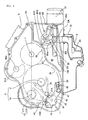
- Fig. 6 is a cross-sectional view taken along line VI-VI of Fig. 5 as viewed from the right side, illustrating the space between the crankcase 2 and the right crankcase cover 32R with the right crankcase cover 32R removed.
- the gear change mechanism 11 includes the shift drum 45, a star-shaped plate 46, a change spindle 47, a change arm 48 welded to an end of the change spindle 47, a restriction bolt 49, and a change arm return spring 50 and the like.
- the change spindle 47 is operatively turned to move the change arm 48, which intermittently turns the star-shaped plate 46 and the shift drum 45.
- the shift fork 43 is moved via a pin 44 to operatively shift the transmission 8 up or down.
- a partition wall 67 is formed along an outer circumference of the clutch 34 and of the primary drive gear 35.
- the partition wall 67 divides a space between the crankcase 2 and the right crankcase cover 32R into two spaces. Of these two spaces, the space which does not include the clutch 34 is used as an oil storage chamber 68.
- the partition wall 67 extends along the outer circumference of the primary drive gear 35 and merges with an upper edge portion 101 of the lower crankcase 2B extending along the crankcase split surface including the crankshaft.
- the upper edge portion 101 further merges with a front wall 102 and a lower wall 103 of the lower crankcase 2B and of the right crankcase cover 32R.
- these partition walls are annularly continuous with one another so as to define a space as the closed oil storage chamber 68.
- the scavenging pump 64 and the feed pump 65 are incorporated in the oil storage chamber 68.
- the scavenging pump 64 and the feed pump 65 are arranged to overlap each other as viewed from the right side.
- the feed pump 65 in the back is seen in the cross-section of Fig. 6 .
- An oil suction pipe 54 equipped with an oil strainer 53 is installed in the oil pan 6 and is connected at its upper end with an suction port 105 of the scavenging pump 64 of Fig. 7 via an oil passage 104 extending in the direction of the crankshaft.
- the oil pan is formed thick.
- the oil storage chamber 68 for storing oil therein is provided in the lateral portion of the crankcase 2; therefore, the oil pan 6 can be replaced with a press-moulded part made of a thin steel plate.
- Fig. 7 is a cross-sectional view taken along line VII-VII of Fig. 5 as viewed from the left. This figure omits the illustration of the clutch 34 for clarity.
- oil discharged from a discharge port 106 of the scavenging pump 64 is stored in the oil storage chamber 68.
- the oil thus stored is sucked from the suction port 108 of the oil suction pipe 107 of Fig. 6 , further sucked from the suction port 65a of the feed pump 65 via the oil suction pipe 107, discharged from the discharge port 65b and supplied to the oil filter 57 at the front wall of the crankcase 2 connecting with the discharge port 65b.
- Purified oil is supplied to lubricating portions of the engine 1 via the main gallery 58.
Landscapes
- Engineering & Computer Science (AREA)
- General Engineering & Computer Science (AREA)
- Mechanical Engineering (AREA)
- Chemical & Material Sciences (AREA)
- Combustion & Propulsion (AREA)
- Lubrication Details And Ventilation Of Internal Combustion Engines (AREA)
- Lubrication Of Internal Combustion Engines (AREA)
Applications Claiming Priority (1)
| Application Number | Priority Date | Filing Date | Title |
|---|---|---|---|
| JP2009087453A JP5202417B2 (ja) | 2009-03-31 | 2009-03-31 | エンジンのオイル溜め構造 |
Publications (3)
| Publication Number | Publication Date |
|---|---|
| EP2239430A2 true EP2239430A2 (de) | 2010-10-13 |
| EP2239430A3 EP2239430A3 (de) | 2011-02-02 |
| EP2239430B1 EP2239430B1 (de) | 2012-03-07 |
Family
ID=42306690
Family Applications (1)
| Application Number | Title | Priority Date | Filing Date |
|---|---|---|---|
| EP10250433A Not-in-force EP2239430B1 (de) | 2009-03-31 | 2010-03-09 | Ölaufbewahrungsstruktur für einen Motor |
Country Status (4)
| Country | Link |
|---|---|
| US (1) | US8316815B2 (de) |
| EP (1) | EP2239430B1 (de) |
| JP (1) | JP5202417B2 (de) |
| AT (1) | ATE548544T1 (de) |
Cited By (2)
| Publication number | Priority date | Publication date | Assignee | Title |
|---|---|---|---|---|
| EP2876333A1 (de) * | 2013-11-20 | 2015-05-27 | Yamaha Hatsudoki Kabushiki Kaisha | Antrieb und im Grätschsitz zu führendes Fahrzeug |
| CN111746694A (zh) * | 2019-03-29 | 2020-10-09 | 本田技研工业株式会社 | 动力单元 |
Families Citing this family (6)
| Publication number | Priority date | Publication date | Assignee | Title |
|---|---|---|---|---|
| JP6223163B2 (ja) * | 2013-12-12 | 2017-11-01 | 川崎重工業株式会社 | 車輌用エンジン及び該エンジンを備えた自動二輪車 |
| JP6216670B2 (ja) * | 2014-03-26 | 2017-10-18 | 本田技研工業株式会社 | パワーユニット |
| JP2016023585A (ja) * | 2014-07-18 | 2016-02-08 | ヤマハ発動機株式会社 | エンジンユニット |
| US11156154B2 (en) * | 2015-12-09 | 2021-10-26 | Honda Motor Co., Ltd. | Internal combustion engine |
| JP2019052615A (ja) | 2017-09-19 | 2019-04-04 | スズキ株式会社 | 内燃機関の潤滑構造 |
| WO2020111188A1 (ja) * | 2018-11-30 | 2020-06-04 | 本田技研工業株式会社 | 鞍乗り型車両 |
Citations (2)
| Publication number | Priority date | Publication date | Assignee | Title |
|---|---|---|---|---|
| JP2578284B2 (ja) | 1992-02-28 | 1997-02-05 | 川崎重工業株式会社 | 内燃機関のオイルポンプ取付け構造 |
| JP3052002B2 (ja) | 1991-03-27 | 2000-06-12 | 本田技研工業株式会社 | ドライサンプ潤滑式内燃機関のオイルタンク構造 |
Family Cites Families (8)
| Publication number | Priority date | Publication date | Assignee | Title |
|---|---|---|---|---|
| US5024287A (en) * | 1987-03-31 | 1991-06-18 | Yamaha Hatsudiki Kabushiki Kaisha | Engine unit for vehicle |
| US4915070A (en) * | 1988-03-31 | 1990-04-10 | Yamaha Hatsudoki Kabushiki Kaisha | Engine unit for motor vehicle |
| US5092292A (en) * | 1989-01-31 | 1992-03-03 | Suzuki Jidosha Kogyo Kabushiki Kaisha | Lubricating apparatus of motorcycle engine |
| JP2646497B2 (ja) * | 1989-02-28 | 1997-08-27 | スズキ株式会社 | 4サイクルエンジンの潤滑油返却装置 |
| JP4212196B2 (ja) * | 1999-09-03 | 2009-01-21 | 本田技研工業株式会社 | 内燃機関用潤滑装置 |
| US7240657B2 (en) * | 2005-06-27 | 2007-07-10 | Kawasaki Jukogyo Kabushiki Kaisha | Lubricating system of engine |
| JP4712644B2 (ja) * | 2006-08-21 | 2011-06-29 | 本田技研工業株式会社 | 内燃機関の潤滑装置 |
| JP4785684B2 (ja) * | 2006-09-11 | 2011-10-05 | 本田技研工業株式会社 | 水冷式内燃機関のポンプ駆動構造 |
-
2009
- 2009-03-31 JP JP2009087453A patent/JP5202417B2/ja not_active Expired - Fee Related
-
2010
- 2010-03-09 AT AT10250433T patent/ATE548544T1/de active
- 2010-03-09 EP EP10250433A patent/EP2239430B1/de not_active Not-in-force
- 2010-03-11 US US12/721,762 patent/US8316815B2/en not_active Expired - Fee Related
Patent Citations (2)
| Publication number | Priority date | Publication date | Assignee | Title |
|---|---|---|---|---|
| JP3052002B2 (ja) | 1991-03-27 | 2000-06-12 | 本田技研工業株式会社 | ドライサンプ潤滑式内燃機関のオイルタンク構造 |
| JP2578284B2 (ja) | 1992-02-28 | 1997-02-05 | 川崎重工業株式会社 | 内燃機関のオイルポンプ取付け構造 |
Cited By (3)
| Publication number | Priority date | Publication date | Assignee | Title |
|---|---|---|---|---|
| EP2876333A1 (de) * | 2013-11-20 | 2015-05-27 | Yamaha Hatsudoki Kabushiki Kaisha | Antrieb und im Grätschsitz zu führendes Fahrzeug |
| US9441734B2 (en) | 2013-11-20 | 2016-09-13 | Yamaha Hatsudoki Kabushiki Kaisha | Power unit and straddle-type vehicle |
| CN111746694A (zh) * | 2019-03-29 | 2020-10-09 | 本田技研工业株式会社 | 动力单元 |
Also Published As
| Publication number | Publication date |
|---|---|
| JP5202417B2 (ja) | 2013-06-05 |
| US20100242893A1 (en) | 2010-09-30 |
| US8316815B2 (en) | 2012-11-27 |
| ATE548544T1 (de) | 2012-03-15 |
| EP2239430B1 (de) | 2012-03-07 |
| JP2010236486A (ja) | 2010-10-21 |
| EP2239430A3 (de) | 2011-02-02 |
Similar Documents
| Publication | Publication Date | Title |
|---|---|---|
| EP2239430B1 (de) | Ölaufbewahrungsstruktur für einen Motor | |
| US8002653B2 (en) | Power unit having engine and continuously variable transmission, configuration thereof, and vehicle incorporating same | |
| US7578277B2 (en) | Pump drive structure of water-cooled internal combustion engine | |
| US7178498B2 (en) | Lubrication system for an engine | |
| US7913817B2 (en) | Oil pump unit for internal combustion engine | |
| EP2006200A1 (de) | Antriebseinheit für ein Motorrad | |
| CA2631490C (en) | Power unit for motocycle | |
| US6990942B2 (en) | Balancer structure for engine | |
| JP4357322B2 (ja) | 鞍乗り型車両用パワーユニット | |
| WO2017065281A1 (ja) | 鞍乗型車両用ドライブユニット | |
| EP2236806B1 (de) | Einlasskanalstruktur eines verbrennungsmotors | |
| JP4369185B2 (ja) | 並列多気筒エンジン | |
| JP5351587B2 (ja) | 小型車両用内燃機関 | |
| EP2039910B1 (de) | Motor und im Grätschsitz zu führendes Fahrzeug | |
| JP6205974B2 (ja) | エンジンのオイルストレーナ構造 | |
| EP2031211B1 (de) | Motor und im Grätschsitz zu führendes Fahrzeug | |
| JP2009154858A (ja) | エンジン及び鞍乗型車両 | |
| EP2674641A2 (de) | Motor und im Grätschsitz zu führendes Fahrzeug | |
| EP2031275B1 (de) | Motor und im Grätschsitz zu führendes Fahrzeug | |
| JP4105057B2 (ja) | スタータモータを備えた内燃機関 | |
| JP5847152B2 (ja) | 内燃機関 | |
| JP2007278107A (ja) | 鞍乗型車両 |
Legal Events
| Date | Code | Title | Description |
|---|---|---|---|
| PUAI | Public reference made under article 153(3) epc to a published international application that has entered the european phase |
Free format text: ORIGINAL CODE: 0009012 |
|
| AK | Designated contracting states |
Kind code of ref document: A2 Designated state(s): AT BE BG CH CY CZ DE DK EE ES FI FR GB GR HR HU IE IS IT LI LT LU LV MC MK MT NL NO PL PT RO SE SI SK SM TR |
|
| AX | Request for extension of the european patent |
Extension state: AL BA ME RS |
|
| PUAL | Search report despatched |
Free format text: ORIGINAL CODE: 0009013 |
|
| AK | Designated contracting states |
Kind code of ref document: A3 Designated state(s): AT BE BG CH CY CZ DE DK EE ES FI FR GB GR HR HU IE IS IT LI LT LU LV MC MK MT NL NO PL PT RO SE SI SK SM TR |
|
| AX | Request for extension of the european patent |
Extension state: AL BA ME RS |
|
| RIC1 | Information provided on ipc code assigned before grant |
Ipc: F02F 7/00 20060101ALI20101227BHEP Ipc: F01M 11/00 20060101AFI20100712BHEP Ipc: F01M 1/12 20060101ALI20101227BHEP |
|
| 17P | Request for examination filed |
Effective date: 20110418 |
|
| GRAP | Despatch of communication of intention to grant a patent |
Free format text: ORIGINAL CODE: EPIDOSNIGR1 |
|
| RIC1 | Information provided on ipc code assigned before grant |
Ipc: F02F 7/00 20060101ALI20110919BHEP Ipc: F01M 1/12 20060101ALI20110919BHEP Ipc: F01M 11/00 20060101AFI20110919BHEP |
|
| GRAS | Grant fee paid |
Free format text: ORIGINAL CODE: EPIDOSNIGR3 |
|
| GRAA | (expected) grant |
Free format text: ORIGINAL CODE: 0009210 |
|
| AK | Designated contracting states |
Kind code of ref document: B1 Designated state(s): AT BE BG CH CY CZ DE DK EE ES FI FR GB GR HR HU IE IS IT LI LT LU LV MC MK MT NL NO PL PT RO SE SI SK SM TR |
|
| REG | Reference to a national code |
Ref country code: GB Ref legal event code: FG4D |
|
| REG | Reference to a national code |
Ref country code: AT Ref legal event code: REF Ref document number: 548544 Country of ref document: AT Kind code of ref document: T Effective date: 20120315 Ref country code: CH Ref legal event code: EP |
|
| REG | Reference to a national code |
Ref country code: IE Ref legal event code: FG4D |
|
| REG | Reference to a national code |
Ref country code: DE Ref legal event code: R096 Ref document number: 602010000957 Country of ref document: DE Effective date: 20120503 |
|
| REG | Reference to a national code |
Ref country code: NL Ref legal event code: VDEP Effective date: 20120307 |
|
| PG25 | Lapsed in a contracting state [announced via postgrant information from national office to epo] |
Ref country code: LT Free format text: LAPSE BECAUSE OF FAILURE TO SUBMIT A TRANSLATION OF THE DESCRIPTION OR TO PAY THE FEE WITHIN THE PRESCRIBED TIME-LIMIT Effective date: 20120307 Ref country code: NO Free format text: LAPSE BECAUSE OF FAILURE TO SUBMIT A TRANSLATION OF THE DESCRIPTION OR TO PAY THE FEE WITHIN THE PRESCRIBED TIME-LIMIT Effective date: 20120607 Ref country code: NL Free format text: LAPSE BECAUSE OF FAILURE TO SUBMIT A TRANSLATION OF THE DESCRIPTION OR TO PAY THE FEE WITHIN THE PRESCRIBED TIME-LIMIT Effective date: 20120307 Ref country code: HR Free format text: LAPSE BECAUSE OF FAILURE TO SUBMIT A TRANSLATION OF THE DESCRIPTION OR TO PAY THE FEE WITHIN THE PRESCRIBED TIME-LIMIT Effective date: 20120307 |
|
| LTIE | Lt: invalidation of european patent or patent extension |
Effective date: 20120307 |
|
| PG25 | Lapsed in a contracting state [announced via postgrant information from national office to epo] |
Ref country code: FI Free format text: LAPSE BECAUSE OF FAILURE TO SUBMIT A TRANSLATION OF THE DESCRIPTION OR TO PAY THE FEE WITHIN THE PRESCRIBED TIME-LIMIT Effective date: 20120307 Ref country code: GR Free format text: LAPSE BECAUSE OF FAILURE TO SUBMIT A TRANSLATION OF THE DESCRIPTION OR TO PAY THE FEE WITHIN THE PRESCRIBED TIME-LIMIT Effective date: 20120608 Ref country code: LV Free format text: LAPSE BECAUSE OF FAILURE TO SUBMIT A TRANSLATION OF THE DESCRIPTION OR TO PAY THE FEE WITHIN THE PRESCRIBED TIME-LIMIT Effective date: 20120307 |
|
| REG | Reference to a national code |
Ref country code: AT Ref legal event code: MK05 Ref document number: 548544 Country of ref document: AT Kind code of ref document: T Effective date: 20120307 |
|
| PG25 | Lapsed in a contracting state [announced via postgrant information from national office to epo] |
Ref country code: CY Free format text: LAPSE BECAUSE OF FAILURE TO SUBMIT A TRANSLATION OF THE DESCRIPTION OR TO PAY THE FEE WITHIN THE PRESCRIBED TIME-LIMIT Effective date: 20120307 |
|
| PG25 | Lapsed in a contracting state [announced via postgrant information from national office to epo] |
Ref country code: RO Free format text: LAPSE BECAUSE OF FAILURE TO SUBMIT A TRANSLATION OF THE DESCRIPTION OR TO PAY THE FEE WITHIN THE PRESCRIBED TIME-LIMIT Effective date: 20120307 Ref country code: BE Free format text: LAPSE BECAUSE OF FAILURE TO SUBMIT A TRANSLATION OF THE DESCRIPTION OR TO PAY THE FEE WITHIN THE PRESCRIBED TIME-LIMIT Effective date: 20120307 Ref country code: IS Free format text: LAPSE BECAUSE OF FAILURE TO SUBMIT A TRANSLATION OF THE DESCRIPTION OR TO PAY THE FEE WITHIN THE PRESCRIBED TIME-LIMIT Effective date: 20120707 Ref country code: CZ Free format text: LAPSE BECAUSE OF FAILURE TO SUBMIT A TRANSLATION OF THE DESCRIPTION OR TO PAY THE FEE WITHIN THE PRESCRIBED TIME-LIMIT Effective date: 20120307 Ref country code: MC Free format text: LAPSE BECAUSE OF NON-PAYMENT OF DUE FEES Effective date: 20120331 Ref country code: SE Free format text: LAPSE BECAUSE OF FAILURE TO SUBMIT A TRANSLATION OF THE DESCRIPTION OR TO PAY THE FEE WITHIN THE PRESCRIBED TIME-LIMIT Effective date: 20120307 Ref country code: SI Free format text: LAPSE BECAUSE OF FAILURE TO SUBMIT A TRANSLATION OF THE DESCRIPTION OR TO PAY THE FEE WITHIN THE PRESCRIBED TIME-LIMIT Effective date: 20120307 Ref country code: EE Free format text: LAPSE BECAUSE OF FAILURE TO SUBMIT A TRANSLATION OF THE DESCRIPTION OR TO PAY THE FEE WITHIN THE PRESCRIBED TIME-LIMIT Effective date: 20120307 Ref country code: PL Free format text: LAPSE BECAUSE OF FAILURE TO SUBMIT A TRANSLATION OF THE DESCRIPTION OR TO PAY THE FEE WITHIN THE PRESCRIBED TIME-LIMIT Effective date: 20120307 |
|
| PG25 | Lapsed in a contracting state [announced via postgrant information from national office to epo] |
Ref country code: PT Free format text: LAPSE BECAUSE OF FAILURE TO SUBMIT A TRANSLATION OF THE DESCRIPTION OR TO PAY THE FEE WITHIN THE PRESCRIBED TIME-LIMIT Effective date: 20120709 Ref country code: SK Free format text: LAPSE BECAUSE OF FAILURE TO SUBMIT A TRANSLATION OF THE DESCRIPTION OR TO PAY THE FEE WITHIN THE PRESCRIBED TIME-LIMIT Effective date: 20120307 |
|
| REG | Reference to a national code |
Ref country code: IE Ref legal event code: MM4A |
|
| PLBE | No opposition filed within time limit |
Free format text: ORIGINAL CODE: 0009261 |
|
| STAA | Information on the status of an ep patent application or granted ep patent |
Free format text: STATUS: NO OPPOSITION FILED WITHIN TIME LIMIT |
|
| PG25 | Lapsed in a contracting state [announced via postgrant information from national office to epo] |
Ref country code: AT Free format text: LAPSE BECAUSE OF FAILURE TO SUBMIT A TRANSLATION OF THE DESCRIPTION OR TO PAY THE FEE WITHIN THE PRESCRIBED TIME-LIMIT Effective date: 20120307 Ref country code: DK Free format text: LAPSE BECAUSE OF FAILURE TO SUBMIT A TRANSLATION OF THE DESCRIPTION OR TO PAY THE FEE WITHIN THE PRESCRIBED TIME-LIMIT Effective date: 20120307 Ref country code: IE Free format text: LAPSE BECAUSE OF NON-PAYMENT OF DUE FEES Effective date: 20120309 |
|
| REG | Reference to a national code |
Ref country code: FR Ref legal event code: ST Effective date: 20130104 |
|
| 26N | No opposition filed |
Effective date: 20121210 |
|
| PG25 | Lapsed in a contracting state [announced via postgrant information from national office to epo] |
Ref country code: FR Free format text: LAPSE BECAUSE OF NON-PAYMENT OF DUE FEES Effective date: 20120507 Ref country code: MK Free format text: LAPSE BECAUSE OF FAILURE TO SUBMIT A TRANSLATION OF THE DESCRIPTION OR TO PAY THE FEE WITHIN THE PRESCRIBED TIME-LIMIT Effective date: 20120307 Ref country code: IT Free format text: LAPSE BECAUSE OF FAILURE TO SUBMIT A TRANSLATION OF THE DESCRIPTION OR TO PAY THE FEE WITHIN THE PRESCRIBED TIME-LIMIT Effective date: 20120307 |
|
| REG | Reference to a national code |
Ref country code: DE Ref legal event code: R097 Ref document number: 602010000957 Country of ref document: DE Effective date: 20121210 |
|
| PG25 | Lapsed in a contracting state [announced via postgrant information from national office to epo] |
Ref country code: ES Free format text: LAPSE BECAUSE OF FAILURE TO SUBMIT A TRANSLATION OF THE DESCRIPTION OR TO PAY THE FEE WITHIN THE PRESCRIBED TIME-LIMIT Effective date: 20120618 |
|
| PG25 | Lapsed in a contracting state [announced via postgrant information from national office to epo] |
Ref country code: BG Free format text: LAPSE BECAUSE OF FAILURE TO SUBMIT A TRANSLATION OF THE DESCRIPTION OR TO PAY THE FEE WITHIN THE PRESCRIBED TIME-LIMIT Effective date: 20120607 Ref country code: MT Free format text: LAPSE BECAUSE OF FAILURE TO SUBMIT A TRANSLATION OF THE DESCRIPTION OR TO PAY THE FEE WITHIN THE PRESCRIBED TIME-LIMIT Effective date: 20120307 |
|
| PG25 | Lapsed in a contracting state [announced via postgrant information from national office to epo] |
Ref country code: TR Free format text: LAPSE BECAUSE OF FAILURE TO SUBMIT A TRANSLATION OF THE DESCRIPTION OR TO PAY THE FEE WITHIN THE PRESCRIBED TIME-LIMIT Effective date: 20120307 |
|
| PG25 | Lapsed in a contracting state [announced via postgrant information from national office to epo] |
Ref country code: LU Free format text: LAPSE BECAUSE OF NON-PAYMENT OF DUE FEES Effective date: 20120309 Ref country code: SM Free format text: LAPSE BECAUSE OF FAILURE TO SUBMIT A TRANSLATION OF THE DESCRIPTION OR TO PAY THE FEE WITHIN THE PRESCRIBED TIME-LIMIT Effective date: 20120307 |
|
| PG25 | Lapsed in a contracting state [announced via postgrant information from national office to epo] |
Ref country code: HU Free format text: LAPSE BECAUSE OF FAILURE TO SUBMIT A TRANSLATION OF THE DESCRIPTION OR TO PAY THE FEE WITHIN THE PRESCRIBED TIME-LIMIT Effective date: 20100309 |
|
| REG | Reference to a national code |
Ref country code: CH Ref legal event code: PL |
|
| REG | Reference to a national code |
Ref country code: DE Ref legal event code: R084 Ref document number: 602010000957 Country of ref document: DE |
|
| GBPC | Gb: european patent ceased through non-payment of renewal fee |
Effective date: 20140309 |
|
| REG | Reference to a national code |
Ref country code: DE Ref legal event code: R084 Ref document number: 602010000957 Country of ref document: DE Effective date: 20141120 |
|
| PG25 | Lapsed in a contracting state [announced via postgrant information from national office to epo] |
Ref country code: GB Free format text: LAPSE BECAUSE OF NON-PAYMENT OF DUE FEES Effective date: 20140309 Ref country code: LI Free format text: LAPSE BECAUSE OF NON-PAYMENT OF DUE FEES Effective date: 20140331 Ref country code: CH Free format text: LAPSE BECAUSE OF NON-PAYMENT OF DUE FEES Effective date: 20140331 |
|
| PGFP | Annual fee paid to national office [announced via postgrant information from national office to epo] |
Ref country code: DE Payment date: 20210224 Year of fee payment: 12 |
|
| REG | Reference to a national code |
Ref country code: DE Ref legal event code: R119 Ref document number: 602010000957 Country of ref document: DE |
|
| PG25 | Lapsed in a contracting state [announced via postgrant information from national office to epo] |
Ref country code: DE Free format text: LAPSE BECAUSE OF NON-PAYMENT OF DUE FEES Effective date: 20221001 |