EP2239459A2 - Transportsystem zum Transport eines Holms - Google Patents
Transportsystem zum Transport eines Holms Download PDFInfo
- Publication number
- EP2239459A2 EP2239459A2 EP10158285A EP10158285A EP2239459A2 EP 2239459 A2 EP2239459 A2 EP 2239459A2 EP 10158285 A EP10158285 A EP 10158285A EP 10158285 A EP10158285 A EP 10158285A EP 2239459 A2 EP2239459 A2 EP 2239459A2
- Authority
- EP
- European Patent Office
- Prior art keywords
- frame structure
- root
- spar
- fixation device
- transport system
- Prior art date
- Legal status (The legal status is an assumption and is not a legal conclusion. Google has not performed a legal analysis and makes no representation as to the accuracy of the status listed.)
- Granted
Links
Images




Classifications
-
- F—MECHANICAL ENGINEERING; LIGHTING; HEATING; WEAPONS; BLASTING
- F03—MACHINES OR ENGINES FOR LIQUIDS; WIND, SPRING, OR WEIGHT MOTORS; PRODUCING MECHANICAL POWER OR A REACTIVE PROPULSIVE THRUST, NOT OTHERWISE PROVIDED FOR
- F03D—WIND MOTORS
- F03D13/00—Assembly, mounting or commissioning of wind motors; Arrangements specially adapted for transporting wind motor components
- F03D13/40—Arrangements or methods specially adapted for transporting wind motor components
-
- Y—GENERAL TAGGING OF NEW TECHNOLOGICAL DEVELOPMENTS; GENERAL TAGGING OF CROSS-SECTIONAL TECHNOLOGIES SPANNING OVER SEVERAL SECTIONS OF THE IPC; TECHNICAL SUBJECTS COVERED BY FORMER USPC CROSS-REFERENCE ART COLLECTIONS [XRACs] AND DIGESTS
- Y02—TECHNOLOGIES OR APPLICATIONS FOR MITIGATION OR ADAPTATION AGAINST CLIMATE CHANGE
- Y02E—REDUCTION OF GREENHOUSE GAS [GHG] EMISSIONS, RELATED TO ENERGY GENERATION, TRANSMISSION OR DISTRIBUTION
- Y02E10/00—Energy generation through renewable energy sources
- Y02E10/70—Wind energy
- Y02E10/72—Wind turbines with rotation axis in wind direction
-
- Y—GENERAL TAGGING OF NEW TECHNOLOGICAL DEVELOPMENTS; GENERAL TAGGING OF CROSS-SECTIONAL TECHNOLOGIES SPANNING OVER SEVERAL SECTIONS OF THE IPC; TECHNICAL SUBJECTS COVERED BY FORMER USPC CROSS-REFERENCE ART COLLECTIONS [XRACs] AND DIGESTS
- Y10—TECHNICAL SUBJECTS COVERED BY FORMER USPC
- Y10T—TECHNICAL SUBJECTS COVERED BY FORMER US CLASSIFICATION
- Y10T29/00—Metal working
- Y10T29/49—Method of mechanical manufacture
- Y10T29/49316—Impeller making
- Y10T29/49332—Propeller making
Definitions
- the present invention relates to a transport system for transporting at least one blade or spar for a wind turbine.
- the blade or spar has a root end and a tip end.
- the transport system comprises a root frame structure for holding the root end and a fixation device adapted to fixate and support the blade or spar between the root end and tip end.
- the vehicle used is a truck with a truck bed in connection with an accompanying trailer.
- Such transports are often accompanied by a couple of additional vehicles in order to provide sufficient safety for the surrounding road users.
- the rotor blades are often made from a spar which is arranged in a mould. Subsequently, the final rotor blade is moulded around the spar. Handling of the intermediate product, the spar, and the final product, the rotor blade, at the manufacturing plant is also very complicated.
- An object of the present invention is, at least partly, to overcome the above disadvantages and drawbacks of the prior art and to provide an improved transport system enabling blades or spars for a wind turbine to be transported inside or outside the manufacturing site in an easy manner.
- a transport system for transporting at least one blade or spar for a wind turbine the blade or spar having a root end and a tip end and the transport system comprising:
- a transport unit such as a tractor or a truck, can easily move one blade or spar by lifting the root frame structure and roll the blade or spar to a new location.
- the root frame structure may comprise a root support means, such as a projecting flange or a seat, for receiving the root end.
- the root end may easily be positioned in the root frame structure.
- the fixation device may comprise at least one device fixation means for receiving the blade or spar, the device fixation means having a configuration which conforms to an outside shape of the blade and/or the spar.
- the blade or spar may be fixated sideways in the horizontal plane of the transport system.
- the device fixation means may have a padding means for abutting the outside of the blade or spar.
- the fixation device When the fixation device is provided with padding means, the outside of the blade or spar is not scratched when arranged in the fixation device.
- the device fixation means may comprise a hose clamp.
- the device fixation means may have a first and a second part, the first part being hingedly connected to the second part.
- the blade or spar may easily be placed in the fixation means.
- the transport system may further comprise a main frame structure to which the root frame structure is connectable.
- the root frame structure can thus be connected to the main frame structure already placed in a new location, making it possible to use the transportation unit for other purposes.
- the fixation device may have device connection means for connecting to a second fixation device so that one fixation device can be stacked on top of another.
- the main frame structure may have main frame support means for supporting two or more root frame structures.
- blades or spars can thus be placed in the same main frame structure.
- all blades or spars can be moved simultaneously by lifting the main frame structure.
- the main frame support means may be positioned on a first side of the main frame structure for connection to a root frame structure and a frame projecting means may be provided on a second side of the main frame structure opposite the first side, the frame projecting means projecting from the second side so that, when loaded with the root frame structure, the main frame structure maintains an upright position.
- the main frame structure is thus able to stand alone without any supportive means, also when several root frame structures are loaded onto the main frame structure.
- the main frame support means may be a crossbar on which a device projecting means of the fixation device may be supported.
- the fixation device When having a crossbar, the fixation device is easily arranged in the main frame structure.
- the root frame structure may moreover have root frame connection means adapted to receive a second root frame structure so that one root frame structure can be stacked on top of another.
- a second root frame structure can be stacked on top of another root frame structure.
- the fixation device may have at least two wheels arranged at each side of the fixation device so that the wheels project sideways from the fixation device when one fixation device is stacked on top of another.
- the wheels When placing the wheels at least partly on the side of the fixation device, the wheels do not hinder that fixation devices may be stacked on top of each other, and the wheels moreover do not increase the stacking height.
- the transport system may comprise a base frame structure for receiving at least one fixation device.
- fixation devices may be secured in the base frame structure.
- the invention further relates to a transport arrangement comprising two transport systems as described above, wherein the fixation devices are stacked one on top of another and are arranged in the same base frame structure so that the blades or spars attached to the first transport system lie in the opposite direction of the blades or spars attached to the second transport system.
- two sets of blades or spars overlap each other so that the tip of one blade or spar from one set of blades or spars is positioned in between two roots of blades or spars from the second set of blades or spars, the blades or spars of each of the sets being arranged one on top of another.
- the invention relates to a mounting method for mounting of one or more blades or spars for a wind turbine before transport, the blade or spar having a root end and a tip end and the method comprising the steps of:
- the mounting method may comprise the additional steps of:
- a transport system 1 for transporting a spar 2 for producing a rotor blade of a wind turbine is shown in Fig. 1 .
- the transport system 1 is shown transporting a spar 2; however, the transport system could just as well be used for transporting a rotor blade.
- the rotor blade 2 is typically produced from a spar, which is a kind of frame structure.
- the spar is placed in a mould and the rotor blade 2 is moulded into its final shape around the spar.
- the invention will mainly be described in relation to a spar 2, even though it might just as well be used for a rotor blade.
- the spar 2 has a root end 3 which is adapted to be mounted in the hub of the wind turbine when the spar has been made into a rotor blade.
- the other end 4 of the spar 2 is a tip and the spar tapers from the root end 3 into the tip.
- the transport system 1 comprises a root frame structure 5 supporting the root end 3 of the spar 2.
- the transport system further comprises a fixation device 6 which is adapted to fixate and support the spar 2 between the root end 3 and tip end 4.
- the fixation device 6 has two rolling means, such as wheels 7 arranged on a shaft extending underneath the fixation device, the wheels being arranged in each end of the shaft so that wheels are situated at each side of the fixation device.
- a transport unit such as a tractor, a pallet jack, or a pallet truck, can easily move the spar 2 or rotor blade by first lifting and then pushing and/or dragging the root frame structure 5.
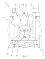
- the spar 2 mounted in the fixation device 6 and the root frame structure 5 is in Fig. 1 shown in perspective and in Fig. 2 from the tip 4 end of the spar.
- the fixation device 6 is arranged between the tip 4 and root end 3 of the spar 2.
- the position of the fixation device 6 along the spar 2 may be varied. When lifting up the root frame structure 5, the tip 4 of the spar 2 comes closer to the ground, and the fixation device 6 has to be arranged at a position along the spar so that the tip does not hit the ground when the root frame structure is lifted.
- the fixation device 6 comprises an open frame structure having a base structure and two sides 13 enabling the spar 2 to enter between the sides of the frame and into a device fixation means 9.
- the device fixation means comprises a lower 12 and an upper 11 part.
- the lower part 12 is hingedly connected to the upper part 11 of the device fixation means and the upper part is arranged in an upright position when the spar 2 is to be fixated in the fixation device 6. Subsequently, the upper part 11 is closed as a lid onto the lower part 12 or the spar 2.
- the position of the fixation device 6 along the spar 2 is thus also determined by the dimensions of the clamp and the spar, respectively.
- the clamp 9 has a padding means 10 along its inner face 27 to protect the spar 2 during transport.
- the device fixation means 9 is a fixed clamp into which the spar has to enter from the side of the clamp.
- the tip of the spar 2 enters the clamp first, after which the spar is pushed into the clamp until the spar has a diameter too large to enter the clamp.
- the clamp 9 may have padding means 10 along its inner face to protect the spar 2 during transport.
- the device fixation means 9 comprises an upper 11 and a lower part 12.
- the spar is positioned on the lower part 12 and the upper part 11 is subsequently placed on top of the spar.
- the upper part 11 is fastened on one side of the spar 2 by a hose clamp 14 or a fastening means, such as a nylon belt.
- the hose clamps or fastening means are part of the device fixation means 9 and are fastened to a rod 40 which is fastened in hook means 41.
- Two bolts 42 are arranged to block the exit of the rod 40 from the hook means 41.
- 3b are, for the purpose of illustration, not tightened around the outside of the spar. However, in reality the fastening means is tightened around the spar.
- the fastening means do not scratch the spar as it is usually made of nylon or the like material. If hose clamps are used, they may have some padding material on the inside towards the spar.
- Both the upper 11 and lower part 12 are provided with a padding means 10 or the like resilient protection means so that the spar 2 is not scratched during transport.
- the shape of the device fixation means 9 conforms to an outside shape of the spar 2 and/or the spar; however, the device fixation means could also be in the form of two plates clamped around the spar.
- the spar is also fixated sideways in the horizontal plane of the transport system 1 before clamping.
- the tip end of the spar is fixated in its recumbent position and, in the embodiment of Figs. 3a and 3b , the tip end is fixated in its upright position.
- the fixation device 6 When the fixation device 6 only has one wheel 7, the wheel is positioned under the fixation device.
- the fixation device 6 may also be provided with more wheels 7 than two, such as four wheels. When the fixation device 6 has four wheels 7, the wheels are arranged two and two on two separate shafts.
- the root frame structure 5 is a frame structure.
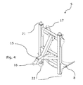
- the root frame structure 5 comprises a root support means 8, such as a projecting flange or a seat, for receiving the root end 3 as shown in Fig. 4 .
- the spar 2 is easily positioned in the root frame structure 5 by placing the root end 3 in the seat.
- the root frame structure 5 has a projecting connection part 15 having a hole 16 for connection to the transport unit, such as a tractor.
- the root frame structure 5 may have other holes for fastening the root end 3 to the root frame structure.
- a plate 17 fastened to the root frame structure 5 may have an elongated hole through which a screw or bolt can enter in order to fasten the root 3 of the spar 2.
- the holes are elongated to ensure that it is always possible to penetrate both the hole in the plate 17 and a hole in the root 3 of the spar 2.
- the spar 2 is moulded around a spar, and the transport system can also be used for transporting the spar.
- the root frame structure 5 is then fastened to the root end of the spar and the device fixation means 9 of the fixation device 6 is fastened around the spar between the tip and the root end.
- the spar is transported to the moulding site simply by lifting the root frame structure 5 and rolling the spar on the wheels 7 of the fixation device 6 to the new location.
- the spar is arranged in the mould by releasing the device fixation means 9 and arranging a belt around the spar and a wire in the hole 16 of the projecting part 15 in order to lift the spar into the mould.
- the root frame structure 5 follows the spar into the mould since the root of the spar is fastened in the root frame structure, which at this point is not equipped with any root support means 8, such as a seat or the like projecting flange.
- the seat or flange may be connected to the root frame structure 5 after the moulding process.
- the root frame structure 5 follows the spar 2 from the point where the spar is only a spar to the point where the spar is to be mounted on the hub of the wind turbine at the installation site.
- the fixation device 6 of Fig. 3 has device connection means in the form of projecting parts 20 and indentations 19.
- the projecting parts 20 are in the form of studs positioned on top of the fixation device 6 for connection to a second fixation device, and the indentations 19 are positioned in the bottom part of the fixation device for receiving the projecting parts.
- a second fixation device can thus be stacked on top of the first fixation device 6 during storage or transportation of the spars 2.
- root frame structure 5 is provided with root frame connection means in the form of studs 21 and indentations 22. In this way, a second root frame structure can be positioned on top of the first root frame structure 5 during storage or transportation of the spars.
- the fixation device 6 has at least two wheels 7 arranged at each side 13 of the fixation device and projecting from the side of the fixation device, it is easy to stack several fixation devices 6 on top of each other.
- the stacking height is not increased by the wheels 7, but is determined solely by the height of the side 13 of the fixation devices 6.
- the root frame structure 5 may be placed in a main frame structure 33 for storing the spar 2 or the spar. Also, when moving the spar 2 to a new location, the root frame structure 5 can be placed in the main frame structure 33 already placed in the new location, allowing the transport unit to be used for another purpose.
- the main frame structure 33 has main frame support means 18 for supporting more than one root frame structure 5 at the same time.
- main frame structure 33 holds several root frame structures 5, all spars 2 or spars can be moved simultaneously by lifting the main frame structure 33 instead of each root frame structure.
- the main frame structure 33 is provided with main frame support means 18 on a first side and, on a second side opposite the first side, with a frame projecting means 37.
- the frame projecting means projects from the second side so the main frame structure 33 may maintain an upright position when loaded with the root frame structure 5.
- the frame projecting means is shown as a base frame 38 extending perpendicular to the bottom of the main frame structure 33 and being linked via a support beam to the upper part of the main frame structure 33.
- the main frame structure 33 has room for three rows of root frame structures 5, each row having room for two spars 2.
- the main frame support means 18 is in the form of a crossbar on which the first root frame structure 5 is arranged. As can be seen in Fig. 8 , two crossbars 18 are arranged in a raised position and a lower crossbar is arranged between the two raised crossbars. Furthermore, each main frame support means 18 has a main frame connection means 36 in the form of a set of studs for receiving a root frame structure 5.
- the root frame structure 5 has indentations 22 for receiving the studs and thus fasten the root frame structure onto the main frame structure 33.
- the main frame structure 33 is designed with more crossbars 18 so that each root frame structure 5 is placed on a crossbar or the like main frame support means, in addition to being stacked on top of another root frame structure.
- the spars 2 are stacked one on top of another in a transport arrangement 100 comprising two transport systems 1.
- the transport arrangement 100 has two main frame structures, a front main frame structure 29 and a back main frame structure 30.
- the front main frame structure 29 is positioned on a first transport unit 28 and the back main frame structure 30 is positioned on a second transport unit 31.
- the first transport unit 28 is connected directly to a transport vehicle and the second transport unit 31 is a truck bed linked by the spars to be drawn after the transport vehicle.
- the front and the back main frame structures vary in that one has two raised main frame portions 34 and one lowered main frame portion 35 and the other one has one raised main frame portion 34 and two lowered main frame portions 35.
- the transport arrangement 100 further comprises a base frame structure 26 for support and fixation of several fixation devices 6.
- the base frame structure 26 has a raised frame portion 23 and a lowered frame portion 24. Each frame portion has indentations 25 for fixation of the fixation devices 6.
- the base frame structure 26 is positioned on the truck bed 31 but may also be placed on the first transport unit if the first transport unit 28 was a truck bed.
- each spar 2 is fastened in a fixation device 6 and in a root frame structure 5 and, subsequently, arranged in the base frame structure 26 and the two main frame structures 29, 30.
- the root frame structures 5 of the first three spars 2 are each arranged on a crossbar 18 in the first main frame structure and on the studs of the main frame structure, and the fixation devices 6 of the same first three spars are likewise arranged in the base frame structure on the frame portions 23, 24.
- the next three spars 3 are arranged thus that their root frame structures 5 are provided in the second main frame structure and their fixation devices 6 are arranged on top of the fixation devices of the first three spars.
- spars 2 can be stacked on top of each other until 12 spars are arranged in the transport arrangement 100.
- the tips of spars 2 arranged in the first main frame structure face the roots of spars arranged in the second main frame structure.
- the spars 2 overlap each other so that the room between two spars are utilised.
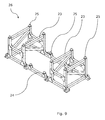
- the base frame structure 26 is shown in Fig. 9 and has two raised portions 23 and one lowered portion 24.
- the base frame structure has projecting parts 25 in order to fasten in the indentations of the fixation device.
- a beam 32 is fastened on top of the fixation devices to link the fixation devices and provide an increased safety during transport.
- each root frame structure 5 is fastened to the main frame structure by a fastening means, such as a typical nylon belt used in relation to trucks.
- the fastening means is secured into the holes of the projecting part 15 and in some fastening parts 39 on the main frame.
- the transport system 1 may also comprise a base frame structure 26.
- the base frame structure 26 can be located at different positions at the production site and a spar 2 arranged in a root frame structure and in a fixation device can easily be moved from one base frame structure to another at the site.
- Spars each arranged in a transport system and the transport systems stacked in a base frame structure can also be moved as a whole by lifting up the base frame structure and the stacked root frame structures by means of a crane.
- the spars or spars are easily stacked on top of each other and the transport system provides a safety distance between the spars or spars during transport. Furthermore, the transport system provides a transport solution where the several spars arranged in the transport systems can be lifted together or the spars can be lifted separately or only part of them together depending on the power of the crane present.
- the spars 2 or spars are mounted on the transport system 1 by fastening a root end 3 of a first spar or spar to a first root frame structure 5 and placing the first spar or spar in a first fixation device 6.
- a second root end 3 of a second spar 2 or spar may be fastened to a second root frame structure 5, and the second spar or spar may be placed in a second fixation device 6. Subsequently, the first root frame structure 5 is connected to a main frame structure and the second fixation device is arranged onto the first fixation device. Finally, the second root frame structure 5 is arranged onto the first root frame structure.
- the fixation device has another kind of rolling means such as roller arranged underneath the fixation device.
- a wind turbine By a wind turbine is meant any kind of apparatus able to convert wind power into electricity, such as a wind generator, wind power unit (WPU), or wind energy converter (WEC).
- a wind turbine nacelle 1 is meant any kind of housing housing the drive train 26 of the wind turbine, e.g. the generator, the gear, etc.
Landscapes
- Engineering & Computer Science (AREA)
- Life Sciences & Earth Sciences (AREA)
- Sustainable Development (AREA)
- Sustainable Energy (AREA)
- Chemical & Material Sciences (AREA)
- Combustion & Propulsion (AREA)
- Mechanical Engineering (AREA)
- General Engineering & Computer Science (AREA)
- Wind Motors (AREA)
- Screw Conveyors (AREA)
Applications Claiming Priority (3)
| Application Number | Priority Date | Filing Date | Title |
|---|---|---|---|
| US16570409P | 2009-04-01 | 2009-04-01 | |
| CN200910141907.9A CN101850874B (zh) | 2009-04-01 | 2009-04-01 | 用于运输翼梁的运输系统、运输装置及其安装方法 |
| DKPA200900444 | 2009-04-01 |
Publications (3)
| Publication Number | Publication Date |
|---|---|
| EP2239459A2 true EP2239459A2 (de) | 2010-10-13 |
| EP2239459A3 EP2239459A3 (de) | 2015-07-08 |
| EP2239459B1 EP2239459B1 (de) | 2016-10-12 |
Family
ID=42341489
Family Applications (1)
| Application Number | Title | Priority Date | Filing Date |
|---|---|---|---|
| EP10158285.6A Not-in-force EP2239459B1 (de) | 2009-04-01 | 2010-03-30 | Transportsystem zum Transport eines Holms |
Country Status (3)
| Country | Link |
|---|---|
| US (1) | US8342491B2 (de) |
| EP (1) | EP2239459B1 (de) |
| ES (1) | ES2602462T3 (de) |
Cited By (11)
| Publication number | Priority date | Publication date | Assignee | Title |
|---|---|---|---|---|
| EP2418376A1 (de) * | 2010-08-12 | 2012-02-15 | Lm Glasfiber A/S | Transport- und Speichersystem für Windturbinenschaufeln |
| EP2620389A1 (de) * | 2012-01-26 | 2013-07-31 | Siemens Aktiengesellschaft | Haltesystem für Rotorblätter einer Windkraftanlage, Transport-System und Verfahren zum Transportieren von Rotorblättern einer Windkraftanlage damit |
| EP2669506A1 (de) * | 2012-06-01 | 2013-12-04 | Siemens Aktiengesellschaft | Handhabung von gebogenen Schaufeln mit versetzten gegenüber liegenden Fußenden während der Stapelung |
| EP2669507A1 (de) * | 2012-06-01 | 2013-12-04 | Siemens Aktiengesellschaft | Transportieren und Stapeln von einander gegenüber und übereinander liegenden gebogenen Schaufeln |
| EP2699492A4 (de) * | 2011-04-20 | 2014-10-08 | A2Sea As | Klingenträger |
| EP2796709A1 (de) * | 2013-04-23 | 2014-10-29 | Siemens Aktiengesellschaft | Windturbinenschaufelhalteanordnung |
| DK177951B1 (en) * | 2013-03-01 | 2015-02-02 | Envision Energy Denmark Aps | Two or three wind turbine blades as one unit |
| WO2015108894A1 (en) * | 2014-01-16 | 2015-07-23 | Bnsf Logistics, Llc | System for transporting wind turbine blades |
| WO2015149809A1 (en) * | 2014-03-31 | 2015-10-08 | Vestas Wind Systems A/S | Stacking wind turbine blades for sea transport |
| US9709025B2 (en) | 2012-10-26 | 2017-07-18 | Lm Wp Patent Holding A/S | Method and system for transporting and storing at least two wind turbine blades |
| US10954920B2 (en) | 2015-12-30 | 2021-03-23 | Vestas Wind Systems A/S | Transport frame for a wind turbine blade |
Families Citing this family (18)
| Publication number | Priority date | Publication date | Assignee | Title |
|---|---|---|---|---|
| EP2035257B1 (de) * | 2006-06-20 | 2011-03-23 | Vestas Wind Systems A/S | Fahrzeug für den transport einer windturbinenschaufel, steuersystem und verfahren für den transport einer windturbine |
| WO2010034732A1 (en) * | 2008-09-29 | 2010-04-01 | Vestas Wind Systems A/S | Telescopic vehicle and method for transporting a long object |
| DE102011113482B4 (de) | 2011-09-13 | 2013-04-18 | Nordex Energy Gmbh | Schutzeinrichtung für ein Rotorblatt einer Windenergieanlage |
| US8602700B2 (en) * | 2012-02-16 | 2013-12-10 | General Electric Company | Shipping fixture and method for transporting rotor blades |
| ES2621508T3 (es) * | 2012-10-26 | 2017-07-04 | Lm Wp Patent Holding A/S | Método y sistema para transportar y almacenar al menos dos palas de turbina eólica |
| DK3041777T3 (en) * | 2013-09-03 | 2018-07-23 | Vestas Wind Sys As | TURNING STANDS FOR A ROTOR NAV OF A WINDMILL AND PROCEDURE TO TURN THE ROTOR NAV |
| US9347426B2 (en) | 2014-08-25 | 2016-05-24 | Transportation Technology Services, Inc. | Wind turbine blade railroad transportation system and method |
| US9315200B1 (en) | 2015-01-27 | 2016-04-19 | Transportation Technology Services, Inc. | Wind turbine blade railroad transportation with two axis translation |
| WO2016183416A1 (en) * | 2015-05-14 | 2016-11-17 | Bnsf Logistics, Llc | Systems and methods for transporting wind turbine blades |
| GB201523122D0 (en) * | 2015-12-30 | 2016-02-10 | Vestas Wind Sys As | Transport frames for a wind turbine blade |
| CN106428982B (zh) * | 2016-04-29 | 2018-06-15 | 沈阳透平机械股份有限公司 | 离心压缩机转子转运装置 |
| US9790927B1 (en) | 2016-08-04 | 2017-10-17 | Bnsf Logistics, Llc | Wind turbine blade double pivot transportation system and method |
| US10731634B2 (en) * | 2016-09-02 | 2020-08-04 | Lm Wind Power Us Technology Aps | Transportation and storage system for a wind turbine blade |
| US10518905B2 (en) * | 2017-07-10 | 2019-12-31 | Textron Innnovations Inc. | System and method for rotorcraft blade storage |
| US10844841B2 (en) * | 2018-08-23 | 2020-11-24 | Bnsf Logistics, Llc | Transportation fixtures for wind turbine blades |
| US10697437B1 (en) * | 2019-08-27 | 2020-06-30 | Bnsf Logistics, Llc | Rotatable support fixture for wind turbine blade |
| CN114616173A (zh) * | 2019-09-05 | 2022-06-10 | Zsm控股有限责任公司 | 用于装货和卸货货运飞机的系统和方法 |
| WO2025073326A1 (en) * | 2023-10-03 | 2025-04-10 | Vestas Wind Systems A/S | Transporter |
Family Cites Families (12)
| Publication number | Priority date | Publication date | Assignee | Title |
|---|---|---|---|---|
| NZ523576A (en) * | 2000-07-10 | 2006-08-31 | Aloys Wobben | Device for handling unit loads |
| DE10200401A1 (de) * | 2002-01-08 | 2003-07-24 | Aloys Wobben | Vorrichtung zum Handhaben von Stückgütern |
| DE10214161C1 (de) * | 2002-03-28 | 2003-05-28 | Willibald Hergeth | Behältnis und Palette zur Aufnahme von Schaufeln einer Strömungsmaschine |
| BRPI0405546F1 (pt) * | 2004-12-10 | 2016-03-22 | Tecsis Tecnologia E Sist S Avançados Ltda | desenvolvimento em conjunto de estruturas para manuseio, transporte e armazenamento de pás para rotores de aerogeradores |
| US8632286B2 (en) * | 2006-04-28 | 2014-01-21 | General Electric Company | Transportation unit for a wind turbine rotor blade |
| BRPI0602764B1 (pt) * | 2006-07-04 | 2016-03-22 | Tecsis Tecnologia E Sist S Avançados Ltda | método e embalagem para transporte de pás de aerogeradores |
| ES2320959B1 (es) * | 2007-03-30 | 2010-03-12 | GAMESA INNOVATION & TECHNOLOGY, S.L. | Soporte para el transporte de palas. |
| US7967536B2 (en) * | 2008-05-02 | 2011-06-28 | Gamesa Innovation & Technology, S.L. | Blade transportation |
| US8186916B2 (en) * | 2008-06-09 | 2012-05-29 | General Electric Company | System and method for transporting wind turbine tower sections on a shipping vessel |
| CN102123886B (zh) * | 2008-08-18 | 2014-03-19 | 西门子公司 | 用于将风力涡轮机元件固定到车辆的固定系统和方法 |
| WO2010034732A1 (en) * | 2008-09-29 | 2010-04-01 | Vestas Wind Systems A/S | Telescopic vehicle and method for transporting a long object |
| US8511921B2 (en) * | 2009-12-07 | 2013-08-20 | General Electric Company | System and method for arranging wind turbine blades |
-
2010
- 2010-03-30 ES ES10158285.6T patent/ES2602462T3/es active Active
- 2010-03-30 EP EP10158285.6A patent/EP2239459B1/de not_active Not-in-force
- 2010-03-30 US US12/749,558 patent/US8342491B2/en not_active Expired - Fee Related
Non-Patent Citations (1)
| Title |
|---|
| None |
Cited By (24)
| Publication number | Priority date | Publication date | Assignee | Title |
|---|---|---|---|---|
| WO2012019895A1 (en) | 2010-08-12 | 2012-02-16 | Lm Glasfiber A/S | Transportation and storage system for wind turbine blades |
| EP2418376A1 (de) * | 2010-08-12 | 2012-02-15 | Lm Glasfiber A/S | Transport- und Speichersystem für Windturbinenschaufeln |
| US9371178B2 (en) | 2010-08-12 | 2016-06-21 | Lm Glasfiber A/S | Transportation and storage system for wind turbine blades |
| EP3026258A1 (de) * | 2010-08-12 | 2016-06-01 | LM WP Patent Holding A/S | Transport- und speichersystem für windturbinenschaufeln |
| US8967929B2 (en) | 2010-08-12 | 2015-03-03 | Lm Glasfiber A/S | Transportation and storage system for wind turbine blades |
| EP2699492A4 (de) * | 2011-04-20 | 2014-10-08 | A2Sea As | Klingenträger |
| CN104066974B (zh) * | 2012-01-26 | 2017-12-19 | 西门子公司 | 风力涡轮机叶片的保持系统、运输系统和用其运输风力涡轮机叶片的方法 |
| CN104066974A (zh) * | 2012-01-26 | 2014-09-24 | 西门子公司 | 风力涡轮机叶片的保持系统、运输系统和用其运输风力涡轮机叶片的方法 |
| WO2013110405A1 (en) * | 2012-01-26 | 2013-08-01 | Siemens Aktiengesellschaft | Holding system for blades of a wind turbine, transport system and method of transporting blades of a wind turbine therewith |
| EP2620389A1 (de) * | 2012-01-26 | 2013-07-31 | Siemens Aktiengesellschaft | Haltesystem für Rotorblätter einer Windkraftanlage, Transport-System und Verfahren zum Transportieren von Rotorblättern einer Windkraftanlage damit |
| EP2669507A1 (de) * | 2012-06-01 | 2013-12-04 | Siemens Aktiengesellschaft | Transportieren und Stapeln von einander gegenüber und übereinander liegenden gebogenen Schaufeln |
| EP2669506A1 (de) * | 2012-06-01 | 2013-12-04 | Siemens Aktiengesellschaft | Handhabung von gebogenen Schaufeln mit versetzten gegenüber liegenden Fußenden während der Stapelung |
| EP2912305B1 (de) | 2012-10-26 | 2021-03-03 | LM WP Patent Holding A/S | Verfahren und system zum transport und zur lagerung von mindestens zwei windturbinenschaufeln |
| US10589941B2 (en) | 2012-10-26 | 2020-03-17 | LM WP Patent Holdings A/S | Method and system for transporting and storing at least two wind turbine blades |
| US9709025B2 (en) | 2012-10-26 | 2017-07-18 | Lm Wp Patent Holding A/S | Method and system for transporting and storing at least two wind turbine blades |
| DK177951B1 (en) * | 2013-03-01 | 2015-02-02 | Envision Energy Denmark Aps | Two or three wind turbine blades as one unit |
| US9168858B2 (en) | 2013-03-01 | 2015-10-27 | Envision Energy (Denmark) Aps | Two or three wind turbine blades as one unit |
| EP2796709B1 (de) | 2013-04-23 | 2019-03-13 | Siemens Aktiengesellschaft | Windturbinenschaufelhalteanordnung |
| EP2796709A1 (de) * | 2013-04-23 | 2014-10-29 | Siemens Aktiengesellschaft | Windturbinenschaufelhalteanordnung |
| WO2015108894A1 (en) * | 2014-01-16 | 2015-07-23 | Bnsf Logistics, Llc | System for transporting wind turbine blades |
| US9494140B2 (en) | 2014-01-16 | 2016-11-15 | Bnsf Logistics, Llc | Frame support assembly for transporting wind turbine blades |
| US10066606B2 (en) | 2014-03-31 | 2018-09-04 | Vestas Wind Systems A/S | Stacking wind turbine blades for sea transport |
| WO2015149809A1 (en) * | 2014-03-31 | 2015-10-08 | Vestas Wind Systems A/S | Stacking wind turbine blades for sea transport |
| US10954920B2 (en) | 2015-12-30 | 2021-03-23 | Vestas Wind Systems A/S | Transport frame for a wind turbine blade |
Also Published As
| Publication number | Publication date |
|---|---|
| EP2239459A3 (de) | 2015-07-08 |
| ES2602462T3 (es) | 2017-02-21 |
| US20100252977A1 (en) | 2010-10-07 |
| EP2239459B1 (de) | 2016-10-12 |
| US8342491B2 (en) | 2013-01-01 |
Similar Documents
| Publication | Publication Date | Title |
|---|---|---|
| EP2239459B1 (de) | Transportsystem zum Transport eines Holms | |
| US9144863B2 (en) | System and method for handling wind turbine tower sections | |
| DK2456973T3 (en) | PROCEDURE AND DEVICE FOR TRANSPORTING AND FITTING WINDOWS | |
| US8087896B2 (en) | Handling system for a wind turbine nacelle, method for vertical displacement and a wind turbine nacelle and a wind turbine nacelle | |
| US7874805B2 (en) | Hub for a wind turbine | |
| CN101850874B (zh) | 用于运输翼梁的运输系统、运输装置及其安装方法 | |
| US7775753B2 (en) | Transportation system for a wind turbine component, vehicle for a transportation system, displacement system, method of establishing a transportation or displacement and use thereof | |
| EP3046803B1 (de) | Transport und stapelung von windturbinenschaufeln | |
| CN104066974B (zh) | 风力涡轮机叶片的保持系统、运输系统和用其运输风力涡轮机叶片的方法 | |
| EP2354537B1 (de) | Verfahren und Vorrichtung zur Montage einer Windturbine auf See | |
| CN104118660A (zh) | 风力涡轮机叶片保持装置 | |
| CA2695055A1 (en) | Method and arrangement to install a wind-turbine | |
| US8932000B2 (en) | Methods for positioning a large load into a transport position and for positioning a large load into a storage position, trailer and/or lorry | |
| WO2018086837A1 (en) | Transport assembly | |
| JP5323205B2 (ja) | 風車のナセルを取り扱うためのシステム及び方法 | |
| US8851859B2 (en) | Nacelle stand and a method for assembling and testing a nacelle for a wind turbine | |
| US20220289098A1 (en) | Tools and methods for handling tower sections | |
| KR101534672B1 (ko) | 풍력발전기 설치장치 및 이를 이용한 풍력발전기 설치방법 | |
| US20240287967A1 (en) | A segmented wind turbine tower section and method of assembling same | |
| DK2682596T3 (en) | Transport device for a wind turbine rotor, a transport system and a method for transporting at least two rotors | |
| JP2021143599A (ja) | タワー部材の積み上げ方法及びタワー部材の積み上げ方法に用いられる吊り上げ用器具 |
Legal Events
| Date | Code | Title | Description |
|---|---|---|---|
| PUAI | Public reference made under article 153(3) epc to a published international application that has entered the european phase |
Free format text: ORIGINAL CODE: 0009012 |
|
| AK | Designated contracting states |
Kind code of ref document: A2 Designated state(s): AT BE BG CH CY CZ DE DK EE ES FI FR GB GR HR HU IE IS IT LI LT LU LV MC MK MT NL NO PL PT RO SE SI SK SM TR |
|
| AX | Request for extension of the european patent |
Extension state: AL BA ME RS |
|
| RAP1 | Party data changed (applicant data changed or rights of an application transferred) |
Owner name: VESTAS WIND SYSTEMS A/S |
|
| RAP1 | Party data changed (applicant data changed or rights of an application transferred) |
Owner name: VESTAS WIND SYSTEMS A/S |
|
| PUAL | Search report despatched |
Free format text: ORIGINAL CODE: 0009013 |
|
| AK | Designated contracting states |
Kind code of ref document: A3 Designated state(s): AT BE BG CH CY CZ DE DK EE ES FI FR GB GR HR HU IE IS IT LI LT LU LV MC MK MT NL NO PL PT RO SE SI SK SM TR |
|
| AX | Request for extension of the european patent |
Extension state: AL BA ME RS |
|
| RIC1 | Information provided on ipc code assigned before grant |
Ipc: F03D 1/00 20060101AFI20150603BHEP |
|
| 17P | Request for examination filed |
Effective date: 20151218 |
|
| RBV | Designated contracting states (corrected) |
Designated state(s): AT BE BG CH CY CZ DE DK EE ES FI FR GB GR HR HU IE IS IT LI LT LU LV MC MK MT NL NO PL PT RO SE SI SK SM TR |
|
| GRAP | Despatch of communication of intention to grant a patent |
Free format text: ORIGINAL CODE: EPIDOSNIGR1 |
|
| INTG | Intention to grant announced |
Effective date: 20160617 |
|
| GRAS | Grant fee paid |
Free format text: ORIGINAL CODE: EPIDOSNIGR3 |
|
| GRAA | (expected) grant |
Free format text: ORIGINAL CODE: 0009210 |
|
| AK | Designated contracting states |
Kind code of ref document: B1 Designated state(s): AT BE BG CH CY CZ DE DK EE ES FI FR GB GR HR HU IE IS IT LI LT LU LV MC MK MT NL NO PL PT RO SE SI SK SM TR |
|
| REG | Reference to a national code |
Ref country code: GB Ref legal event code: FG4D |
|
| REG | Reference to a national code |
Ref country code: CH Ref legal event code: EP |
|
| REG | Reference to a national code |
Ref country code: AT Ref legal event code: REF Ref document number: 836760 Country of ref document: AT Kind code of ref document: T Effective date: 20161015 |
|
| REG | Reference to a national code |
Ref country code: IE Ref legal event code: FG4D |
|
| REG | Reference to a national code |
Ref country code: DE Ref legal event code: R096 Ref document number: 602010037083 Country of ref document: DE |
|
| REG | Reference to a national code |
Ref country code: LT Ref legal event code: MG4D |
|
| REG | Reference to a national code |
Ref country code: NL Ref legal event code: MP Effective date: 20161012 |
|
| REG | Reference to a national code |
Ref country code: ES Ref legal event code: FG2A Ref document number: 2602462 Country of ref document: ES Kind code of ref document: T3 Effective date: 20170221 |
|
| PG25 | Lapsed in a contracting state [announced via postgrant information from national office to epo] |
Ref country code: LV Free format text: LAPSE BECAUSE OF FAILURE TO SUBMIT A TRANSLATION OF THE DESCRIPTION OR TO PAY THE FEE WITHIN THE PRESCRIBED TIME-LIMIT Effective date: 20161012 |
|
| REG | Reference to a national code |
Ref country code: FR Ref legal event code: PLFP Year of fee payment: 8 |
|
| REG | Reference to a national code |
Ref country code: AT Ref legal event code: MK05 Ref document number: 836760 Country of ref document: AT Kind code of ref document: T Effective date: 20161012 |
|
| PG25 | Lapsed in a contracting state [announced via postgrant information from national office to epo] |
Ref country code: SE Free format text: LAPSE BECAUSE OF FAILURE TO SUBMIT A TRANSLATION OF THE DESCRIPTION OR TO PAY THE FEE WITHIN THE PRESCRIBED TIME-LIMIT Effective date: 20161012 Ref country code: LT Free format text: LAPSE BECAUSE OF FAILURE TO SUBMIT A TRANSLATION OF THE DESCRIPTION OR TO PAY THE FEE WITHIN THE PRESCRIBED TIME-LIMIT Effective date: 20161012 Ref country code: GR Free format text: LAPSE BECAUSE OF FAILURE TO SUBMIT A TRANSLATION OF THE DESCRIPTION OR TO PAY THE FEE WITHIN THE PRESCRIBED TIME-LIMIT Effective date: 20170113 Ref country code: NO Free format text: LAPSE BECAUSE OF FAILURE TO SUBMIT A TRANSLATION OF THE DESCRIPTION OR TO PAY THE FEE WITHIN THE PRESCRIBED TIME-LIMIT Effective date: 20170112 |
|
| PG25 | Lapsed in a contracting state [announced via postgrant information from national office to epo] |
Ref country code: FI Free format text: LAPSE BECAUSE OF FAILURE TO SUBMIT A TRANSLATION OF THE DESCRIPTION OR TO PAY THE FEE WITHIN THE PRESCRIBED TIME-LIMIT Effective date: 20161012 Ref country code: IS Free format text: LAPSE BECAUSE OF FAILURE TO SUBMIT A TRANSLATION OF THE DESCRIPTION OR TO PAY THE FEE WITHIN THE PRESCRIBED TIME-LIMIT Effective date: 20170212 Ref country code: PL Free format text: LAPSE BECAUSE OF FAILURE TO SUBMIT A TRANSLATION OF THE DESCRIPTION OR TO PAY THE FEE WITHIN THE PRESCRIBED TIME-LIMIT Effective date: 20161012 Ref country code: HR Free format text: LAPSE BECAUSE OF FAILURE TO SUBMIT A TRANSLATION OF THE DESCRIPTION OR TO PAY THE FEE WITHIN THE PRESCRIBED TIME-LIMIT Effective date: 20161012 Ref country code: NL Free format text: LAPSE BECAUSE OF FAILURE TO SUBMIT A TRANSLATION OF THE DESCRIPTION OR TO PAY THE FEE WITHIN THE PRESCRIBED TIME-LIMIT Effective date: 20161012 Ref country code: PT Free format text: LAPSE BECAUSE OF FAILURE TO SUBMIT A TRANSLATION OF THE DESCRIPTION OR TO PAY THE FEE WITHIN THE PRESCRIBED TIME-LIMIT Effective date: 20170213 Ref country code: AT Free format text: LAPSE BECAUSE OF FAILURE TO SUBMIT A TRANSLATION OF THE DESCRIPTION OR TO PAY THE FEE WITHIN THE PRESCRIBED TIME-LIMIT Effective date: 20161012 Ref country code: BE Free format text: LAPSE BECAUSE OF FAILURE TO SUBMIT A TRANSLATION OF THE DESCRIPTION OR TO PAY THE FEE WITHIN THE PRESCRIBED TIME-LIMIT Effective date: 20161012 |
|
| REG | Reference to a national code |
Ref country code: DE Ref legal event code: R097 Ref document number: 602010037083 Country of ref document: DE |
|
| PG25 | Lapsed in a contracting state [announced via postgrant information from national office to epo] |
Ref country code: DK Free format text: LAPSE BECAUSE OF FAILURE TO SUBMIT A TRANSLATION OF THE DESCRIPTION OR TO PAY THE FEE WITHIN THE PRESCRIBED TIME-LIMIT Effective date: 20161012 Ref country code: CZ Free format text: LAPSE BECAUSE OF FAILURE TO SUBMIT A TRANSLATION OF THE DESCRIPTION OR TO PAY THE FEE WITHIN THE PRESCRIBED TIME-LIMIT Effective date: 20161012 Ref country code: EE Free format text: LAPSE BECAUSE OF FAILURE TO SUBMIT A TRANSLATION OF THE DESCRIPTION OR TO PAY THE FEE WITHIN THE PRESCRIBED TIME-LIMIT Effective date: 20161012 Ref country code: RO Free format text: LAPSE BECAUSE OF FAILURE TO SUBMIT A TRANSLATION OF THE DESCRIPTION OR TO PAY THE FEE WITHIN THE PRESCRIBED TIME-LIMIT Effective date: 20161012 Ref country code: SK Free format text: LAPSE BECAUSE OF FAILURE TO SUBMIT A TRANSLATION OF THE DESCRIPTION OR TO PAY THE FEE WITHIN THE PRESCRIBED TIME-LIMIT Effective date: 20161012 |
|
| PLBE | No opposition filed within time limit |
Free format text: ORIGINAL CODE: 0009261 |
|
| STAA | Information on the status of an ep patent application or granted ep patent |
Free format text: STATUS: NO OPPOSITION FILED WITHIN TIME LIMIT |
|
| PG25 | Lapsed in a contracting state [announced via postgrant information from national office to epo] |
Ref country code: BG Free format text: LAPSE BECAUSE OF FAILURE TO SUBMIT A TRANSLATION OF THE DESCRIPTION OR TO PAY THE FEE WITHIN THE PRESCRIBED TIME-LIMIT Effective date: 20170112 Ref country code: IT Free format text: LAPSE BECAUSE OF FAILURE TO SUBMIT A TRANSLATION OF THE DESCRIPTION OR TO PAY THE FEE WITHIN THE PRESCRIBED TIME-LIMIT Effective date: 20161012 Ref country code: SM Free format text: LAPSE BECAUSE OF FAILURE TO SUBMIT A TRANSLATION OF THE DESCRIPTION OR TO PAY THE FEE WITHIN THE PRESCRIBED TIME-LIMIT Effective date: 20161012 |
|
| 26N | No opposition filed |
Effective date: 20170713 |
|
| REG | Reference to a national code |
Ref country code: CH Ref legal event code: PL |
|
| PG25 | Lapsed in a contracting state [announced via postgrant information from national office to epo] |
Ref country code: SI Free format text: LAPSE BECAUSE OF FAILURE TO SUBMIT A TRANSLATION OF THE DESCRIPTION OR TO PAY THE FEE WITHIN THE PRESCRIBED TIME-LIMIT Effective date: 20161012 Ref country code: MC Free format text: LAPSE BECAUSE OF FAILURE TO SUBMIT A TRANSLATION OF THE DESCRIPTION OR TO PAY THE FEE WITHIN THE PRESCRIBED TIME-LIMIT Effective date: 20161012 |
|
| REG | Reference to a national code |
Ref country code: IE Ref legal event code: MM4A |
|
| PG25 | Lapsed in a contracting state [announced via postgrant information from national office to epo] |
Ref country code: LU Free format text: LAPSE BECAUSE OF NON-PAYMENT OF DUE FEES Effective date: 20170330 |
|
| PG25 | Lapsed in a contracting state [announced via postgrant information from national office to epo] |
Ref country code: IE Free format text: LAPSE BECAUSE OF NON-PAYMENT OF DUE FEES Effective date: 20170330 Ref country code: CH Free format text: LAPSE BECAUSE OF NON-PAYMENT OF DUE FEES Effective date: 20170331 Ref country code: LI Free format text: LAPSE BECAUSE OF NON-PAYMENT OF DUE FEES Effective date: 20170331 |
|
| REG | Reference to a national code |
Ref country code: FR Ref legal event code: PLFP Year of fee payment: 9 |
|
| PG25 | Lapsed in a contracting state [announced via postgrant information from national office to epo] |
Ref country code: MT Free format text: LAPSE BECAUSE OF NON-PAYMENT OF DUE FEES Effective date: 20170330 |
|
| PG25 | Lapsed in a contracting state [announced via postgrant information from national office to epo] |
Ref country code: HU Free format text: LAPSE BECAUSE OF FAILURE TO SUBMIT A TRANSLATION OF THE DESCRIPTION OR TO PAY THE FEE WITHIN THE PRESCRIBED TIME-LIMIT; INVALID AB INITIO Effective date: 20100330 |
|
| PG25 | Lapsed in a contracting state [announced via postgrant information from national office to epo] |
Ref country code: CY Free format text: LAPSE BECAUSE OF NON-PAYMENT OF DUE FEES Effective date: 20161012 |
|
| PG25 | Lapsed in a contracting state [announced via postgrant information from national office to epo] |
Ref country code: MK Free format text: LAPSE BECAUSE OF FAILURE TO SUBMIT A TRANSLATION OF THE DESCRIPTION OR TO PAY THE FEE WITHIN THE PRESCRIBED TIME-LIMIT Effective date: 20161012 |
|
| PG25 | Lapsed in a contracting state [announced via postgrant information from national office to epo] |
Ref country code: TR Free format text: LAPSE BECAUSE OF FAILURE TO SUBMIT A TRANSLATION OF THE DESCRIPTION OR TO PAY THE FEE WITHIN THE PRESCRIBED TIME-LIMIT Effective date: 20161012 |
|
| PGFP | Annual fee paid to national office [announced via postgrant information from national office to epo] |
Ref country code: FR Payment date: 20230323 Year of fee payment: 14 |
|
| PGFP | Annual fee paid to national office [announced via postgrant information from national office to epo] |
Ref country code: GB Payment date: 20230321 Year of fee payment: 14 Ref country code: DE Payment date: 20230328 Year of fee payment: 14 |
|
| PGFP | Annual fee paid to national office [announced via postgrant information from national office to epo] |
Ref country code: ES Payment date: 20230420 Year of fee payment: 14 |
|
| REG | Reference to a national code |
Ref country code: DE Ref legal event code: R119 Ref document number: 602010037083 Country of ref document: DE |
|
| GBPC | Gb: european patent ceased through non-payment of renewal fee |
Effective date: 20240330 |
|
| PG25 | Lapsed in a contracting state [announced via postgrant information from national office to epo] |
Ref country code: DE Free format text: LAPSE BECAUSE OF NON-PAYMENT OF DUE FEES Effective date: 20241001 |
|
| PG25 | Lapsed in a contracting state [announced via postgrant information from national office to epo] |
Ref country code: GB Free format text: LAPSE BECAUSE OF NON-PAYMENT OF DUE FEES Effective date: 20240330 |
|
| PG25 | Lapsed in a contracting state [announced via postgrant information from national office to epo] |
Ref country code: FR Free format text: LAPSE BECAUSE OF NON-PAYMENT OF DUE FEES Effective date: 20240331 |
|
| PG25 | Lapsed in a contracting state [announced via postgrant information from national office to epo] |
Ref country code: GB Free format text: LAPSE BECAUSE OF NON-PAYMENT OF DUE FEES Effective date: 20240330 Ref country code: FR Free format text: LAPSE BECAUSE OF NON-PAYMENT OF DUE FEES Effective date: 20240331 Ref country code: DE Free format text: LAPSE BECAUSE OF NON-PAYMENT OF DUE FEES Effective date: 20241001 |
|
| REG | Reference to a national code |
Ref country code: ES Ref legal event code: FD2A Effective date: 20250508 |
|
| PG25 | Lapsed in a contracting state [announced via postgrant information from national office to epo] |
Ref country code: ES Free format text: LAPSE BECAUSE OF NON-PAYMENT OF DUE FEES Effective date: 20240331 |