EP2239497A1 - Unterputz-LED-Leuchte - Google Patents
Unterputz-LED-Leuchte Download PDFInfo
- Publication number
- EP2239497A1 EP2239497A1 EP10003108A EP10003108A EP2239497A1 EP 2239497 A1 EP2239497 A1 EP 2239497A1 EP 10003108 A EP10003108 A EP 10003108A EP 10003108 A EP10003108 A EP 10003108A EP 2239497 A1 EP2239497 A1 EP 2239497A1
- Authority
- EP
- European Patent Office
- Prior art keywords
- flush
- led light
- led
- mounted led
- leds
- Prior art date
- Legal status (The legal status is an assumption and is not a legal conclusion. Google has not performed a legal analysis and makes no representation as to the accuracy of the status listed.)
- Granted
Links
Images


Classifications
-
- F—MECHANICAL ENGINEERING; LIGHTING; HEATING; WEAPONS; BLASTING
- F21—LIGHTING
- F21S—NON-PORTABLE LIGHTING DEVICES; SYSTEMS THEREOF; VEHICLE LIGHTING DEVICES SPECIALLY ADAPTED FOR VEHICLE EXTERIORS
- F21S8/00—Lighting devices intended for fixed installation
- F21S8/02—Lighting devices intended for fixed installation of recess-mounted type, e.g. downlighters
- F21S8/024—Lighting devices intended for fixed installation of recess-mounted type, e.g. downlighters intended to be recessed in a wall or like vertical structure, e.g. building facade
-
- F—MECHANICAL ENGINEERING; LIGHTING; HEATING; WEAPONS; BLASTING
- F21—LIGHTING
- F21V—FUNCTIONAL FEATURES OR DETAILS OF LIGHTING DEVICES OR SYSTEMS THEREOF; STRUCTURAL COMBINATIONS OF LIGHTING DEVICES WITH OTHER ARTICLES, NOT OTHERWISE PROVIDED FOR
- F21V21/00—Supporting, suspending, or attaching arrangements for lighting devices; Hand grips
- F21V21/02—Wall, ceiling, or floor bases; Fixing pendants or arms to the bases
- F21V21/04—Recessed bases
-
- F—MECHANICAL ENGINEERING; LIGHTING; HEATING; WEAPONS; BLASTING
- F21—LIGHTING
- F21V—FUNCTIONAL FEATURES OR DETAILS OF LIGHTING DEVICES OR SYSTEMS THEREOF; STRUCTURAL COMBINATIONS OF LIGHTING DEVICES WITH OTHER ARTICLES, NOT OTHERWISE PROVIDED FOR
- F21V23/00—Arrangement of electric circuit elements in or on lighting devices
- F21V23/02—Arrangement of electric circuit elements in or on lighting devices the elements being transformers, impedances or power supply units, e.g. a transformer with a rectifier
-
- F—MECHANICAL ENGINEERING; LIGHTING; HEATING; WEAPONS; BLASTING
- F21—LIGHTING
- F21V—FUNCTIONAL FEATURES OR DETAILS OF LIGHTING DEVICES OR SYSTEMS THEREOF; STRUCTURAL COMBINATIONS OF LIGHTING DEVICES WITH OTHER ARTICLES, NOT OTHERWISE PROVIDED FOR
- F21V29/00—Protecting lighting devices from thermal damage; Cooling or heating arrangements specially adapted for lighting devices or systems
- F21V29/50—Cooling arrangements
- F21V29/70—Cooling arrangements characterised by passive heat-dissipating elements, e.g. heat-sinks
- F21V29/74—Cooling arrangements characterised by passive heat-dissipating elements, e.g. heat-sinks with fins or blades
- F21V29/76—Cooling arrangements characterised by passive heat-dissipating elements, e.g. heat-sinks with fins or blades with essentially identical parallel planar fins or blades, e.g. with comb-like cross-section
- F21V29/763—Cooling arrangements characterised by passive heat-dissipating elements, e.g. heat-sinks with fins or blades with essentially identical parallel planar fins or blades, e.g. with comb-like cross-section the planes containing the fins or blades having the direction of the light emitting axis
-
- F—MECHANICAL ENGINEERING; LIGHTING; HEATING; WEAPONS; BLASTING
- F21—LIGHTING
- F21S—NON-PORTABLE LIGHTING DEVICES; SYSTEMS THEREOF; VEHICLE LIGHTING DEVICES SPECIALLY ADAPTED FOR VEHICLE EXTERIORS
- F21S8/00—Lighting devices intended for fixed installation
- F21S8/03—Lighting devices intended for fixed installation of surface-mounted type
- F21S8/033—Lighting devices intended for fixed installation of surface-mounted type the surface being a wall or like vertical structure, e.g. building facade
-
- F—MECHANICAL ENGINEERING; LIGHTING; HEATING; WEAPONS; BLASTING
- F21—LIGHTING
- F21Y—INDEXING SCHEME ASSOCIATED WITH SUBCLASSES F21K, F21L, F21S and F21V, RELATING TO THE FORM OR THE KIND OF THE LIGHT SOURCES OR OF THE COLOUR OF THE LIGHT EMITTED
- F21Y2115/00—Light-generating elements of semiconductor light sources
- F21Y2115/10—Light-emitting diodes [LED]
Definitions
- the invention relates to a flush-mounted LED light for the electrical and mechanical connection to a commercially available flush-mounted device box (for example, according to DIN 49073) with at least one LED module and with a connectable to the mains transformer.
- a flush-mounted LED light for the electrical and mechanical connection to a commercially available flush-mounted device box (for example, according to DIN 49073) with at least one LED module and with a connectable to the mains transformer.
- From the DE 203 13 428 U1 is known from a mounting plate, a light-emitting diodes and possibly other electronic components printed circuit board with power supply lines, a light distribution panel and a frame with a light exit opening existing light known.
- the power supply lines are led to a connection box arranged essentially behind the luminaire, in which a transformer which can be connected to the power network is arranged.
- the connection cables of several luminaires behind a wall covering can be routed to a central connection point where a low-voltage source (transformer) is installed.
- the invention has for its object to provide an optimized flush-mounted LED light of the type mentioned.
- a flush-mounted LED light for the electrical and mechanical connection to a standard flush-mounted device box, with a device base, which has a power supply / converter, a connection unit for power lines, a heat sink and at least one connection device for connecting at least one LED module with at least one LED, wherein the at least one LED module is thermally brought into contact with the heat sink and wherein a luminaire cover is provided with at least one light outlet.
- the achievable with the invention advantages are in particular that due to the integration of the power supply / converter in the flush-mounted box a tasteful design with very small and flat design of the externally visible components of the lamp, d. H. the luminaire cover is enabled.
- the cable outlet does not consist of a piece of installation cable hanging from the wall, but the cable outlet is integrated in the flush-mounted box. This has advantages in terms of electrical safety in renovation, z. B. when wallpapering the wall, d. H. Construction measures ensure safe over-papering and subsequent free cutting.
- a significant advantage is the fact that the cooling in addition to the reduction of the temperature of the lamp and an extension of the life of the LEDs (indicated in the half-life, ie up to half the brightness) is achieved.
- FIG. 1 is a view of a suitable for an LED module flush-mounted LED lamp with the luminaire cover removed.
- the flush-mounted LED lamp 1 has a device base 6, on whose upper side a heat sink 11 is arranged, wherein an LED module 15 (LED insert) thermally contacts a side surface of this heat sink 11.
- LED module 15 LED insert
- the device base 6 or the heat sink 11 is provided with guides 12.
- An installation frame 22 completes the flush-mounted LED light 1.
- Fig. 3 a perspective view of an LED module is shown.
- the constructed on a printed circuit board LED module 15 has at least one, but preferably a plurality of light emitting diodes 16, wherein 6 are arranged for electrical contact with the connector 9 of the device base electrical contacts 17 on the circuit board.
- FIG. 4 is a view of a suitable for at least two LED modules flush-mounted LED lamp with the luminaire cover removed.
- the flush-mounted LED light 2 has a device base 6, on the upper side of a cooling body 11 is arranged, wherein at least two LED modules 15 thermally contact different, opposite side surfaces of the heat sink 11. For precise guidance and locking of these LED modules 15 of the device base 6 or the heat sink 11 with guides 12, 13 is provided.
- An installation frame 22 completes the flush-mounted LED light 2.
- the LED module 15 or the LED modules 15 nestles against the heat sink 11 when inserted into the slot. This prevents overheating of the LEDs 16, which in turn significantly increases the life of the LEDs.
- To guide an LED module 15 guides / slots in the housing of the device base 6 or the heat sink 11 are provided. Of course, the heat sink 11 also serves to dissipate the heat loss of the power supply / converter. 7
- contact between the connector 9 and the electrical contacts 17 can also be a fixed installation, in particular Soldering of the electrical connection between an LED module 15 and the power supply / converter 7 associated circuit board done.
- a front-side light outlet may also be provided in the light cover 18.
- the device base 6 For mounting a flush-mounted LED light 1 - 4 in a standard flush-mounted box according to DIN 49073, the device base 6 is first mounted in the usual manner by means of its spreading claws or by means of its support ring mounting means (screws) in the flush-mounted box. Thereafter, the LED modules 15 are inserted in the desired number in the connector 9, 10. Finally, the made of plastic and designed in the desired design luminaire cover 18 is pressed and locked.
- the installation frame 22 can either be arranged as a separate component between the device base 6 and the light cover 18 or alternatively be designed as an integral component of the device base 6.
Landscapes
- Engineering & Computer Science (AREA)
- General Engineering & Computer Science (AREA)
- Power Engineering (AREA)
- Arrangement Of Elements, Cooling, Sealing, Or The Like Of Lighting Devices (AREA)
- Non-Portable Lighting Devices Or Systems Thereof (AREA)
Abstract
Description
- Die Erfindung betrifft eine Unterputz-LED-Leuchte für den elektrischen und mechanischen Anschluss an einer handelsüblichen UP-Gerätedose (z. B. nach DIN 49073) mit mindestens einem LED-Modul und mit einem an das Stromnetz anschließbaren Transformator.
- Aus der
DE 203 13 428 U1 ist eine aus einer Montageplatte, einer mit Leuchtdioden und gegebenenfalls weiteren elektronischen Bauteilen bestückten Leiterplatte mit Stromzuführungsleitungen, einer Lichtverteilungsscheibe und einem Blendrahmen mit einer Lichtaustrittsöffnung bestehende Leuchte bekannt. Die Stromzuführungsleitungen sind zu einer im Wesentlichen hinter der Leuchte angeordneten Anschlussdose geführt, in der ein an das Stromnetz anschließbarer Transformator angeordnet ist. Es können die Anschlussleitungen mehrerer Leuchten hinter einem Wandbelag (Fliesen, Fliesenspiegel) zu einer zentralen Anschlussstelle geführt sein, an der eine Niederspannungsquelle (Trafo) installiert ist. - Der Erfindung liegt die Aufgabe zugrunde, eine optimierte Unterputz-LED-Leuchte der eingangs genannten Art anzugeben.
- Diese Aufgabe wird erfindungsgemäß gelöst durch eine Unterputz-LED-Leuchte für den elektrischen und mechanischen Anschluss an einer handelsüblichen UP-Gerätedose, mit einem Gerätesockel, welcher ein Netzteil/Konverter, eine Anschlusseinheit für Netzleitungen, einen Kühlkörper und mindestens eine Anschlussvorrichtung zum Anschluss mindestens eines LED-Moduls mit mindestens einer LED aufweist, wobei das mindestens eine LED-Modul thermisch mit dem Kühlkörper in Kontakt gebracht ist und wobei eine Leuchten-Abdeckung mit mindestens einem Lichtauslass vorgesehen ist.
- Die mit der Erfindung erzielbaren Vorteile bestehen insbesondere darin, dass aufgrund der Integration des Netzteils/Konverters in die UP-Gerätedose eine geschmackvolle Ausgestaltung mit sehr kleiner und flacher Bauform der außen sichtbaren Komponenten der Leuchte, d. h. der Leuchten-Abdeckung, ermöglicht wird. Im Vergleich zu allgemein üblichen Wandleuchten besteht der Leitungsauslass nicht aus einem aus der Wand heraushängenden Stück Installationsleitung, sondern der Leitungsauslass ist in der UP-Gerätedose integriert. Dies hat Vorteile hinsichtlich der elektrischen Sicherheit bei Renovierungsmaßnahmen, z. B. beim Tapezieren der Wand, d. h. bei Renovierungsmaßnahmen ist ein gefahrloses Übertapezieren und nachträgliches Freischneiden sichergestellt. Aufgrund der vom Netzteil/Konverter sekundärseitig erzeugten, vom Netz getrennten, berührbaren Kleinspannung müssen hinsichtlich der außen sichtbaren Baukomponenten der Leuchte keine isolierenden Maßnahmen getroffen werden und der Freiheitsgrad zur Entwicklung unterschiedlicher Designvarianten der Leuchte wird erhöht. Aufgrund des vorgeschlagenen Stecksystems können vom Endkunden/Anwender LED-Module unterschiedlicher Lichtfarbe selbst ausgetauscht werden.
- Ein wesentlicher Vorteil ist darin zu sehen, dass durch die Kühlung neben der Reduzierung der Temperatur der Leuchte auch eine Verlängerung der Lebensdauer der LEDs (angegeben in der Halbwertszeit, also bis zur halben Helligkeit) erzielt wird.
- Des Weiteren ist es möglich, das Design der Leuchten-Abdeckung und des Installationsrahmens entsprechend einem für Steckdosen, Schalter usw. bereits existierenden respektive zu entwickelnden Unterputz-Installationsprogramm auszurichten. Ein weiterer Vorteil ist darin zu sehen, dass die Gefahr des Anbohrens der elektrischen Leitung am Leitungsauslass beim Befestigen der Leuchte nicht mehr gegeben ist. Vorteilhafte Ausgestaltungen der Erfindung sind in den Unteransprüchen gekennzeichnet.
- Die Erfindung wird nachstehend an Hand der in der Zeichnung dargestellten Ausführungsbeispiele gelöst. Es zeigen:
- Fig. 1
- eine Sicht auf eine für ein LED-Modul geeignete Unterputz-LED-Leuchte mit entfernter Leuchten-Abdeckung,
- Fig. 2
- einen seitlichen Schnitt durch eine Unterputz-LED-Leuchte gemäß
Fig. 1 , - Fig. 3
- eine perspektivische Ansicht eines LED-Moduls,
- Fig. 4
- eine Sicht auf eine für mindestens zwei LED-Module geeignete Unter- putz-LED-Leuchte mit entfernter Leuchten-Abdeckung,
- Fig. 5
- einen seitlichen Schnitt durch eine Unterputz-LED-Leuchte gemäß
Fig. 4 , - Fig. 6 - 9
- eine Sicht auf Unterputz-LED-Leuchten mit unterschiedlich vielen LED- Moduln.
- In
Fig. 1 ist eine Sicht auf eine für ein LED-Modul geeignete Unterputz-LED-Leuchte mit entfernter Leuchten-Abdeckung dargestellt. Die Unterputz-LED-Leuchte 1 weist einen Gerätesockel 6 auf, an dessen Oberseite ein Kühlkörper 11 angeordnet ist, wobei ein LED-Modul 15 (LED-Einsatz) eine Seitenfläche dieses Kühlkörpers 11 thermisch kontaktiert. Zur präzisen Führung und Arretierung des LED-Moduls 15 ist der Gerätesockel 6 oder der Kühlkörper 11 mit Führungen 12 versehen. Ein Installationsrahmen 22 komplettiert die Unterputz-LED-Leuchte 1. - In
Fig. 2 ist ein seitlicher Schnitt durch eine Unterputz-LED-Leuchte gemäßFig. 1 dargestellt. Es sind die wesentlichen Komponenten der Unterputz-LED-Leuchte 1 gezeigt: - der Gerätesockel 6 mit einer Anschlusseinheit 8 für 230V-Netzleitungen, einem Netzteil/Konverter 7, vorzugsweise inklusive Steuer/Regeleinrichtung, dem Kühlkörper 11 und dem LED-Modul 15, welches bodenseitig einen Steckverbinder 9 des Gerätesockels 6 kontaktiert,
- eine Leuchten-Abdeckung 18 mit einem seitlichen Lichtauslass 19 mit Streuscheibe oder Linse,
- der Installationsrahmen (Abdeckrahmen) 22.
- In
Fig. 3 ist eine perspektivische Ansicht eines LED-Moduls dargestellt. Das auf einer Leiterplatte aufgebaute LED-Modul 15 weist mindestens eine, vorzugsweise jedoch mehrere Leuchtdioden 16 auf, wobei zur elektrischen Kontaktierung mit dem Steckverbinder 9 des Gerätesockels 6 elektrische Kontakte 17 auf der Leiterplatte angeordnet sind. - In
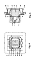
Fig. 4 ist eine Sicht auf eine für mindestens zwei LED-Module geeignete Unterputz-LED-Leuchte mit entfernter Leuchten-Abdeckung dargestellt. Die Unterputz-LED-Leuchte 2 weist einen Gerätesockel 6 auf, an dessen Oberseite ein Kühlkörper 11 angeordnet ist, wobei mindestens zwei LED-Module 15 unterschiedliche, sich gegenüberliegende Seitenflächen des Kühlkörpers 11 thermisch kontaktieren. Zur präzisen Führung und Arretierung dieser LED-Module 15 ist der Gerätesockel 6 oder der Kühlkörper 11 mit Führungen 12, 13 versehen. Ein Installationsrahmen 22 komplettiert die Unterputz-LED-Leuchte 2. - In
Fig. 5 ist ein seitlicher Schnitt durch eine Unterputz-LED-Leuchte gemäßFig. 4 dargestellt. Es sind die wesentlichen Komponenten der Unterputz-LED-Leuchte 2 gezeigt: - der Gerätesockel 6 mit der Anschlusseinheit 8 für 230V-Netzleitungen, dem Netzteil/Konverter 7 inklusive Steuer/Regeleinrichtung, dem Kühlkörper 11 und zwei LED-Moduln 15, welche bodenseitig Steckverbinder 9, 10 des Gerätesockels 6 kontaktieren,
- eine Leuchten-Abdeckung 18 mit zwei seitlichen Lichtauslässen 19, 20 mit Streuscheibe oder Linse,
- der Installationsrahmen (Abdeckrahmen) 22.
- In den
Fig. 6 - 9 ist eine Sicht auf Unterputz-LED-Leuchten mit unterschiedlich vielen LED-Moduln dargestellt: - die Unterputz-LED-Leuchte 1 gemäß
Fig. 6 weist ein LED-Modul 15 auf, welches eine Seitenfläche des Kühlkörpers 11 kontaktiert, - die Unterputz-LED-Leuchte 2 gemäß
Fig. 7 weist zwei sich gegenüberliegende LED-Module 15 auf, welche sich gegenüberliegende Seitenflächen des Kühlkörpers 11 kontaktieren, - die Unterputz-LED-Leuchte 3 gemäß
Fig. 8 weist drei U-förmig zueinander angeordnete LED-Module 15 auf, welche drei Seitenflächen des Kühlkörpers 11 kontaktieren, - die Unterputz-LED-Leuchte 4 gemäß
Fig. 9 weist vier LED-Module 15 auf, welche alle vier Seitenflächen des Kühlkörpers 11 kontaktieren. - Wie aus den vorstehenden Erläuterungen hervorgeht, kann die Leiterplatte des Netzteils/Konverters 7 auf ihrer Rückseite einen Steckplatz inklusive Steckverbinder für ein LED-Modul oder mehrere Steckplätze inklusive Steckverbinder für zwei, drei oder vier LED-Module aufweisen, wodurch ein beliebiges Bestücken der Unterputz-LED-Leuchte mit LED-Moduln 15 unterschiedliche Beleuchtungseinrichtungen erzielt werden können:
- eine einseitige Beleuchtungseinrichtung,
- eine zweiseitige Beleuchtungseinrichtung,
- eine dreiseitige Beleuchtungseinrichtung,
- eine vierseitige Beleuchtungseinrichtung.
- Wichtig ist, dass sich das LED-Modul 15 respektive die LED-Module 15 beim Einschieben in den Steckplatz gegen den Kühlkörper 11 anschmiegt / anschmiegen. Hierdurch wird eine Überhitzung der LEDs 16 verhindert, was wwiederum die Lebensdauer der LEDs deutlich erhöht. Zur Führung eines LED-Moduls 15 sind Führungen / Schlitze im Gehäuse des Gerätesockels 6 oder des Kühlkörpers 11 vorgesehen. Selbstverständlich dient der Kühlkörper 11 gleichermaßen zur Abführung der Verlustwärme des Netzteils/Konverters 7.
- Alternativ zur vorstehend erläuterten Kontaktierung zwischen dem Steckverbinder 9 und den elektrischen Kontakten 17 kann auch eine feste Montage, insbesondere Verlötung der elektrischen Verbindung zwischen einem LED-Modul 15 und der dem Netzteil/Konverter 7 zugeordneten Leiterplatte erfolgen.
- Alternativ oder zusätzlich zu den vorstehend erläuterten seitlichen Lichtauslässen 19, 20 kann auch ein frontseitiger Lichtauslass in der Leuchten-Abdeckung 18 vorgesehen sein.
- In weiterer Ausgestaltung kann die Unterputz-LED-Leuchte 1 - 4 auch in folgenden Ausführungsformen realisiert werden:
- In der Leuchten-Abdeckung 18 der Unterputz-LED-Leuchte 1 - 4 ist zusätzlich eine Schalteinheit zum händischen EIN-/AUS-Schalten der LEDs 16 integriert.
- In der Unterputz-LED-Leuchte 1 - 4 ist zusätzlich ein Empfänger für drahtlose Fernbedienungs-Signale integriert, welcher eine Schalteinheit zum ferngesteuerten EIN-/AUS-Schalten der LEDs 16 ansteuert.
- In der Unterputz-LED-Leuchte 1 - 4 ist zusätzlich ein Bewegungsmelder inklusive Schalteinheit integriert, um derart ein automatisches EIN-/AUS-Schalten der LEDs 16 in Abhängigkeit von detektierter Bewegung zu ermöglichen.
- In der Unterputz-LED-Leuchte 1 - 4 ist zusätzlich ein Dämmerungsschalter inklusive Schalteinheit integriert, um derart ein automatisches EIN-/AUS-Schalten der LEDs 16 in Abhängigkeit von der aktuell vorliegenden Helligkeit zu ermöglichen.
- In der Unterputz-LED-Leuchte 1 - 4 ist zusätzlich ein Buskoppler inklusive Schalteinheit integriert, um derart ein ferngesteuertes EIN-/AUS-Schalten der LEDs 16 über einen Bus der Gebäudesystemtechnik zu ermöglichen.
- Selbstverständlich können diese Ausführungsformen auch kumulativ eingesetzt werden.
- Dabei ist es ganz allgemein im Low-Cost-Bereich nicht erforderlich, eine Steuer- und Regeleinheit (betreffend Netzteil/Konverter) vorzusehen, es reicht vielmehr ein sehr einfaches Netzteil/Koverter aus. Für Unterputz-LED-Leuchten mit beliebiger Anzahl von LED-Modulen (welche vom Anwender zu bestücken sind) wird jedoch vorzugsweise eine Konstantstromquelle verwendet, die nicht ohne Steuer-/Regeleinrichtung möglich ist.
- Zur Montage einer Unterputz-LED-Leuchte 1 - 4 in einer handelsüblichen UP-Gerätedose nach DIN 49073 wird zunächst der Gerätesockel 6 in üblicher Weise mittels seiner Spreizkrallen oder mittels durch seinen Tragring greifende Montagemittel (Schrauben) in der UP-Gerätedose montiert. Danach werden die LED-Module 15 in gewünschter Anzahl in die Steckverbinder 9, 10 eingesteckt. Abschließend wird die aus Kunststoff bestehende und in gewünschtem Design ausgebildete Leuchten-Abdeckung 18 aufgedrückt und verrastet. Der Installationsrahmen 22 kann entweder als separate Komponente zwischen Gerätesockel 6 und Leuchten-Abdeckung 18 angeordnet oder alternativ hierzu als integrale Komponente des Gerätesockels 6 ausgebildet sein.
-
- 1
- Unterputz-LED-Leuchte mit einem LED-Modul
- 2
- Unterputz-LED-Leuchte mit zwei LED-Moduln
- 3
- Unterputz-LED-Leuchte mit drei LED-Moduln
- 4
- Unterputz-LED-Leuchte mit vier LED-Moduln
- 5
- ---
- 6
- Gerätesockel
- 7
- Netzteil/Konverter inklusive Steuer-/Regeleinrichtung
- 8
- Anschlusseinheit für 230V-Netzleitungen
- 9
- Steckverbinder
- 10
- Steckverbinder
- 11
- Kühlkörper
- 12
- Führung für LED-Modul
- 13
- Führung für LED-Modul
- 14
- ---
- 15
- LED-Modul
- 16
- LED
- 17
- elektrische Kontakte
- 18
- Leuchten-Abdeckung
- 19
- Lichtauslass mit Streuscheibe oder Linse
- 20
- Lichtauslass mit Streuscheibe oder Linse
- 21
- ---
- 22
- Installationsrahmen
Claims (8)
- Unterputz-LED-Leuchte (1, 2, 3, 4) für den elektrischen und mechanischen Anschluss an einer handelsüblichen UP-Gerätedose, mit einem Gerätesockel (6), welcher ein Netzteil/Konverter (7), eine Anschlusseinheit (8) für Netzleitungen, einen Kühlkörper (11) und mindestens eine Anschlussvorrichtung zum Anschluss mindestens eines LED-Moduls (15) mit mindestens einer LED (16) aufweist, wobei das mindestens eine LED-Modul (15) thermisch mit dem Kühlkörper (11) in Kontakt gebracht ist und wobei eine Leuchten-Abdeckung (18) mit mindestens einem Lichtauslass (19, 20) vorgesehen ist.
- Unterputz-LED-Leuchte nach Anspruch 1, gekennzeichnet durch ein Netzteil/Konverter (7) inklusive Steuer- und Regeleinrichtung zur Versorgung der LEDs (16) mit einem konstanten Strom.
- Unterputz-LED-Leuchte nach Anspruch 1 oder 2, gekennzeichnet durch die Ausbildung der Anschlussvorrichtung zum Anschluss mindestens eines LED-Moduls (15) in Form eines Steckverbinders (9) zur Kontaktierung elektrischer Kontakte (17) eines LED-Moduls (15) oder mehrerer Steckverbinder (9, 10) zur Kontaktierung mehrerer LED-Module (15).
- Unterputz-LED-Leuchte nach einem der vorstehenden Ansprüche, dadurch gekennzeichnet, dass in der Leuchten-Abdeckung (18) der Unterputz-LED-Leuchte (1 - 4) zusätzlich eine Schalteinheit zum händischen EIN-/AUS-Schalten der LEDs (16) integriert ist.
- Unterputz-LED-Leuchte nach einem der vorstehenden Ansprüche, dadurch gekennzeichnet, dass in der Unterputz-LED-Leuchte (1 - 4) zusätzlich ein Empfänger für drahtlose Fernbedienungs-Signale integriert ist, welcher eine Schalteinheit zum ferngesteuerten EIN-/AUS-Schalten der LEDs (16) ansteuert.
- Unterputz-LED-Leuchte nach einem der vorstehenden Ansprüche, dadurch gekennzeichnet, dass in der Unterputz-LED-Leuchte (1 - 4) zusätzlich ein Bewegungsmelder inklusive Schalteinheit integriert ist, um derart ein automatisches EIN-/AUS-Schalten der LEDs (16) in Abhängigkeit von detektierter Bewegung zu ermöglichen.
- Unterputz-LED-Leuchte nach einem der vorstehenden Ansprüche, dadurch gekennzeichnet, dass in der Unterputz-LED-Leuchte (1 - 4) zusätzlich ein Dämmerungsschalter inklusive Schalteinheit integriert ist, um derart ein automatisches EIN-/AUS-Schalten der LEDs (16) in Abhängigkeit von der aktuell vorliegenden Helligkeit zu ermöglichen.
- Unterputz-LED-Leuchte nach einem der vorstehenden Ansprüche, dadurch gekennzeichnet, dass in der Unterputz-LED-Leuchte (1 - 4) zusätzlich ein Buskoppler inklusive Schalteinheit integriert ist, um derart ein ferngesteuertes EIN-/AUS-Schalten der LEDs (16) über einen Bus der Gebäudesystemtechnik zu ermöglichen.
Applications Claiming Priority (1)
| Application Number | Priority Date | Filing Date | Title |
|---|---|---|---|
| DE102009016778A DE102009016778B4 (de) | 2009-04-07 | 2009-04-07 | Unterputz-LED-Leuchte |
Publications (2)
| Publication Number | Publication Date |
|---|---|
| EP2239497A1 true EP2239497A1 (de) | 2010-10-13 |
| EP2239497B1 EP2239497B1 (de) | 2020-05-20 |
Family
ID=42320771
Family Applications (1)
| Application Number | Title | Priority Date | Filing Date |
|---|---|---|---|
| EP10003108.7A Active EP2239497B1 (de) | 2009-04-07 | 2010-03-24 | Unterputz-LED-Leuchte |
Country Status (4)
| Country | Link |
|---|---|
| EP (1) | EP2239497B1 (de) |
| CN (1) | CN101858546B (de) |
| DE (1) | DE102009016778B4 (de) |
| RU (1) | RU2538781C2 (de) |
Cited By (5)
| Publication number | Priority date | Publication date | Assignee | Title |
|---|---|---|---|---|
| DE102010005505A1 (de) * | 2010-01-23 | 2011-07-28 | Abb Ag, 68309 | Unterputz-LED-Leuchte mit Tragplatte |
| EP2476946A1 (de) * | 2011-01-13 | 2012-07-18 | Abb Ag | Unterputz-LED-Leuchte |
| CN103322515A (zh) * | 2013-06-05 | 2013-09-25 | 潘定国 | Led光引擎、led照明灯具以及led照明系统 |
| CN104896375A (zh) * | 2015-06-10 | 2015-09-09 | 李宝 | 高速公路智能过车记录灯 |
| CN107763514A (zh) * | 2017-11-09 | 2018-03-06 | 广东尔漫照明有限公司 | 一种可切换安装形态的面板灯 |
Families Citing this family (7)
| Publication number | Priority date | Publication date | Assignee | Title |
|---|---|---|---|---|
| DE102012101995A1 (de) | 2012-03-09 | 2013-09-12 | Ropag High Tech E.K. | Elektrogerät mit einem Elektrogehäuse mit einer Halte- und Spannvorrichtung |
| DE202017107161U1 (de) * | 2017-11-27 | 2019-02-28 | Rzb Rudolf Zimmermann, Bamberg Gmbh | Deckel oder Rahmen eines Elektroinstallationsgehäuses, insbesondere einer Abzweig- oder Anschlussdose, und Elektroinstallationsgehäuse, insbesondere Abzweig- oder Anschlussdose |
| DE102018103381B3 (de) * | 2018-02-15 | 2019-03-21 | Insta Gmbh | Elektrische Leuchte |
| DE102018103375B3 (de) | 2018-02-15 | 2019-03-28 | Insta Gmbh | Elektrische Leuchte |
| DE102018103379B3 (de) | 2018-02-15 | 2019-03-21 | Insta Gmbh | Elektrische Leuchte |
| DE102022109513A1 (de) | 2022-04-20 | 2023-10-26 | Insta Gmbh | Unterputzeinsatz, Anordnung umfassend einen solchen mit einer Unterputzdose und Verfahren zum Betrieb eines Aufsatzes |
| DE102022112420B4 (de) | 2022-05-18 | 2026-03-26 | Insta Gmbh | Einsatz und Anordnung umfassend einen solchen mit einer Unterputzdose |
Citations (6)
| Publication number | Priority date | Publication date | Assignee | Title |
|---|---|---|---|---|
| DE20018455U1 (de) * | 2000-10-28 | 2001-01-11 | Ansorg GmbH, 45481 Mülheim | Einbauleuchte |
| DE20101295U1 (de) * | 2001-01-24 | 2001-04-05 | Drees Leuchtenteile GmbH, 59846 Sundern | Beleuchtungseinrichtung zum Betrieb an einem Wechselstromnetz |
| DE20313428U1 (de) | 2003-08-29 | 2003-11-27 | Hoffmeister Leuchten Gmbh | Elektrische Leuchte |
| EP1477726A2 (de) * | 2003-05-16 | 2004-11-17 | Ludwig Leuchten KG | LED- Einbauleuchte |
| DE102007017329A1 (de) * | 2006-04-15 | 2007-10-25 | Gira Giersiepen Gmbh & Co. Kg | Leuchte zur Gebäude-Installation |
| WO2007130536A2 (en) * | 2006-05-05 | 2007-11-15 | Cree Led Lighting Solutions, Inc. | Lighting device |
Family Cites Families (15)
| Publication number | Priority date | Publication date | Assignee | Title |
|---|---|---|---|---|
| DE19919080A1 (de) * | 1999-04-27 | 2000-11-02 | Insta Elektro Gmbh & Co Kg | Beleuchtungseinrichtung |
| RU15071U1 (ru) * | 2000-04-07 | 2000-09-10 | Байкин Александр Иванович | Система управления внутренним освещением |
| RU2263356C2 (ru) * | 2003-07-10 | 2005-10-27 | Андрей Викторович Синюгин | Светотехническое устройство для динамического освещения |
| DE20312932U1 (de) * | 2003-08-18 | 2003-10-30 | Lighting Partner B.V., Goes | Unterputzdose |
| RU39183U1 (ru) * | 2004-04-16 | 2004-07-20 | Марков Валерий Николаевич | Универсальный светодиодный осветитель с микропроцессорным управлением |
| US7170751B2 (en) * | 2005-01-05 | 2007-01-30 | Gelcore Llc | Printed circuit board retaining device |
| DE202005018867U1 (de) * | 2005-12-02 | 2006-01-26 | Wilhelm Koch Gmbh | Bausatz einer Wandleuchte |
| DE202007003457U1 (de) * | 2006-03-29 | 2007-05-16 | Insta Elektro Gmbh | Elektrisches/elektronisches Installationsgerät für die Gebäudesystemtechnik |
| RU58471U1 (ru) * | 2006-05-10 | 2006-11-27 | Общество с ограниченной ответственностью "Предприятие "ЭРМА" | Светильник |
| RU2313199C1 (ru) * | 2006-11-24 | 2007-12-20 | Владимир Павлович Осипенко | Светильник |
| RU64321U1 (ru) * | 2007-02-14 | 2007-06-27 | Владимир Александрович Круглов | Осветительное устройство |
| UA27660U (en) * | 2007-06-26 | 2007-11-12 | Univ Vinnytsia Nat Tech | Lighting unit |
| RU71729U1 (ru) * | 2007-12-04 | 2008-03-20 | Виктор Викторович Сысун | Защищенный световой прибор на мощном светодиоде |
| TWM343924U (en) * | 2008-04-01 | 2008-11-01 | Ya-Hui Chen | Parallel assembling structure of luminant |
| RU80285U1 (ru) * | 2008-09-26 | 2009-01-27 | Дмитрий Сергеевич Гвоздев | Светодиодная лампа |
-
2009
- 2009-04-07 DE DE102009016778A patent/DE102009016778B4/de active Active
- 2009-07-06 CN CN200910151946.7A patent/CN101858546B/zh not_active Expired - Fee Related
-
2010
- 2010-03-24 EP EP10003108.7A patent/EP2239497B1/de active Active
- 2010-04-06 RU RU2010113362/07A patent/RU2538781C2/ru active
Patent Citations (6)
| Publication number | Priority date | Publication date | Assignee | Title |
|---|---|---|---|---|
| DE20018455U1 (de) * | 2000-10-28 | 2001-01-11 | Ansorg GmbH, 45481 Mülheim | Einbauleuchte |
| DE20101295U1 (de) * | 2001-01-24 | 2001-04-05 | Drees Leuchtenteile GmbH, 59846 Sundern | Beleuchtungseinrichtung zum Betrieb an einem Wechselstromnetz |
| EP1477726A2 (de) * | 2003-05-16 | 2004-11-17 | Ludwig Leuchten KG | LED- Einbauleuchte |
| DE20313428U1 (de) | 2003-08-29 | 2003-11-27 | Hoffmeister Leuchten Gmbh | Elektrische Leuchte |
| DE102007017329A1 (de) * | 2006-04-15 | 2007-10-25 | Gira Giersiepen Gmbh & Co. Kg | Leuchte zur Gebäude-Installation |
| WO2007130536A2 (en) * | 2006-05-05 | 2007-11-15 | Cree Led Lighting Solutions, Inc. | Lighting device |
Cited By (7)
| Publication number | Priority date | Publication date | Assignee | Title |
|---|---|---|---|---|
| DE102010005505A1 (de) * | 2010-01-23 | 2011-07-28 | Abb Ag, 68309 | Unterputz-LED-Leuchte mit Tragplatte |
| DE102010005505B4 (de) * | 2010-01-23 | 2015-01-22 | Abb Ag | Unterputz-LED-Leuchte mit Tragplatte |
| EP2476946A1 (de) * | 2011-01-13 | 2012-07-18 | Abb Ag | Unterputz-LED-Leuchte |
| CN103322515A (zh) * | 2013-06-05 | 2013-09-25 | 潘定国 | Led光引擎、led照明灯具以及led照明系统 |
| CN103322515B (zh) * | 2013-06-05 | 2017-02-08 | 潘定国 | Led光引擎、led照明灯具以及led照明系统 |
| CN104896375A (zh) * | 2015-06-10 | 2015-09-09 | 李宝 | 高速公路智能过车记录灯 |
| CN107763514A (zh) * | 2017-11-09 | 2018-03-06 | 广东尔漫照明有限公司 | 一种可切换安装形态的面板灯 |
Also Published As
| Publication number | Publication date |
|---|---|
| RU2010113362A (ru) | 2011-10-20 |
| CN101858546B (zh) | 2014-12-17 |
| HK1150067A1 (en) | 2011-10-28 |
| DE102009016778B4 (de) | 2013-06-27 |
| CN101858546A (zh) | 2010-10-13 |
| EP2239497B1 (de) | 2020-05-20 |
| DE102009016778A1 (de) | 2011-04-07 |
| RU2538781C2 (ru) | 2015-01-10 |
Similar Documents
| Publication | Publication Date | Title |
|---|---|---|
| EP2239497B1 (de) | Unterputz-LED-Leuchte | |
| EP2211084B1 (de) | Leuchte, insbesondere Wandleuchte | |
| EP2348522B1 (de) | Installationsschalter oder -taster mit einer Wippe mit einem Lichtauslass für eine Beleuchtung | |
| EP2348249B1 (de) | Unterputz-LED-Leuchte | |
| DE102007018177B3 (de) | Steckdose mit Orientierungsbeleuchtung | |
| EP2850705B1 (de) | Tragschiene zur halterung und stromversorgung mehrerer leuchtmodule, sowie lichtbandsystem mit einer solchen tragschiene | |
| AT507057A2 (de) | Universelle leuchte zur verwendung als rettungszeichen- und fluchtwegbeleuchtung | |
| DE102018122361A1 (de) | Modulares Leuchtensystem | |
| AT414320B (de) | Elektro-installationseinheit | |
| EP2348792B1 (de) | Unterputz-LED-Leuchte | |
| US9425536B2 (en) | Wall outlet lighting power supply system | |
| EP2838171B1 (de) | Elektrisches Installationsgerät mit Beleuchtungselement | |
| EP2363634A2 (de) | Unterputz-LED-Leuchte, insbesondere Deckenleuchte | |
| DE202012006340U1 (de) | Lampe | |
| DE20101295U1 (de) | Beleuchtungseinrichtung zum Betrieb an einem Wechselstromnetz | |
| DE29711379U1 (de) | Beleuchtungsanlage mit Dimmer | |
| DE102018119656A1 (de) | Mechanischer und elektrischer Aufbau einer Langfeldleuchte und dazugehörige unterschiedliche Betriebsweisen | |
| EP3396234B1 (de) | Beleuchtungseinrichtung | |
| DE102010005505B4 (de) | Unterputz-LED-Leuchte mit Tragplatte | |
| DE102010019454A1 (de) | Trägerprofil für eine Beleuchtung | |
| DE102004030883A1 (de) | Elektrisches System mit Sender und Empfänger | |
| DE102016109042B4 (de) | Vorrichtung und Verfahren zum Anschluss eines elektrischen Geräts an eine elektrische Energieversorgung | |
| DE202005002237U1 (de) | Digitale Lüsterklemme | |
| DE102005011589B4 (de) | Langgestreckte Lampenanordnung | |
| DE102013212671A1 (de) | Variables Decken- bzw. Wandleuchtensystem |
Legal Events
| Date | Code | Title | Description |
|---|---|---|---|
| PUAI | Public reference made under article 153(3) epc to a published international application that has entered the european phase |
Free format text: ORIGINAL CODE: 0009012 |
|
| AK | Designated contracting states |
Kind code of ref document: A1 Designated state(s): AT BE BG CH CY CZ DE DK EE ES FI FR GB GR HR HU IE IS IT LI LT LU LV MC MK MT NL NO PL PT RO SE SI SK SM TR |
|
| AX | Request for extension of the european patent |
Extension state: AL BA ME RS |
|
| 17P | Request for examination filed |
Effective date: 20101125 |
|
| STAA | Information on the status of an ep patent application or granted ep patent |
Free format text: STATUS: EXAMINATION IS IN PROGRESS |
|
| 17Q | First examination report despatched |
Effective date: 20180625 |
|
| RIC1 | Information provided on ipc code assigned before grant |
Ipc: F21V 29/00 20150101ALI20100723BHEP Ipc: F21S 8/00 20060101ALN20100723BHEP Ipc: F21S 8/02 20060101ALI20100723BHEP Ipc: F21V 21/04 20060101AFI20100723BHEP Ipc: F21Y 101/02 20000101ALN20100723BHEP Ipc: F21V 23/02 20060101ALI20100723BHEP |
|
| RAP1 | Party data changed (applicant data changed or rights of an application transferred) |
Owner name: ABB SCHWEIZ AG |
|
| REG | Reference to a national code |
Ref country code: DE Ref legal event code: R079 Ref document number: 502010016640 Country of ref document: DE Free format text: PREVIOUS MAIN CLASS: F21V0021040000 Ipc: F21S0008020000 |
|
| GRAP | Despatch of communication of intention to grant a patent |
Free format text: ORIGINAL CODE: EPIDOSNIGR1 |
|
| STAA | Information on the status of an ep patent application or granted ep patent |
Free format text: STATUS: GRANT OF PATENT IS INTENDED |
|
| RIC1 | Information provided on ipc code assigned before grant |
Ipc: F21S 8/00 20060101ALN20191216BHEP Ipc: F21S 8/02 20060101AFI20191216BHEP Ipc: F21V 23/02 20060101ALI20191216BHEP Ipc: F21V 29/00 20150101ALI20191216BHEP Ipc: F21Y 115/10 20160101ALN20191216BHEP Ipc: F21V 21/04 20060101ALI20191216BHEP |
|
| INTG | Intention to grant announced |
Effective date: 20200121 |
|
| GRAS | Grant fee paid |
Free format text: ORIGINAL CODE: EPIDOSNIGR3 |
|
| GRAA | (expected) grant |
Free format text: ORIGINAL CODE: 0009210 |
|
| STAA | Information on the status of an ep patent application or granted ep patent |
Free format text: STATUS: THE PATENT HAS BEEN GRANTED |
|
| AK | Designated contracting states |
Kind code of ref document: B1 Designated state(s): AT BE BG CH CY CZ DE DK EE ES FI FR GB GR HR HU IE IS IT LI LT LU LV MC MK MT NL NO PL PT RO SE SI SK SM TR |
|
| REG | Reference to a national code |
Ref country code: GB Ref legal event code: FG4D Free format text: NOT ENGLISH |
|
| REG | Reference to a national code |
Ref country code: CH Ref legal event code: EP |
|
| REG | Reference to a national code |
Ref country code: DE Ref legal event code: R096 Ref document number: 502010016640 Country of ref document: DE |
|
| REG | Reference to a national code |
Ref country code: AT Ref legal event code: REF Ref document number: 1272827 Country of ref document: AT Kind code of ref document: T Effective date: 20200615 |
|
| REG | Reference to a national code |
Ref country code: NL Ref legal event code: FP |
|
| REG | Reference to a national code |
Ref country code: LT Ref legal event code: MG4D |
|
| PG25 | Lapsed in a contracting state [announced via postgrant information from national office to epo] |
Ref country code: SE Free format text: LAPSE BECAUSE OF FAILURE TO SUBMIT A TRANSLATION OF THE DESCRIPTION OR TO PAY THE FEE WITHIN THE PRESCRIBED TIME-LIMIT Effective date: 20200520 Ref country code: LT Free format text: LAPSE BECAUSE OF FAILURE TO SUBMIT A TRANSLATION OF THE DESCRIPTION OR TO PAY THE FEE WITHIN THE PRESCRIBED TIME-LIMIT Effective date: 20200520 Ref country code: IS Free format text: LAPSE BECAUSE OF FAILURE TO SUBMIT A TRANSLATION OF THE DESCRIPTION OR TO PAY THE FEE WITHIN THE PRESCRIBED TIME-LIMIT Effective date: 20200920 Ref country code: PT Free format text: LAPSE BECAUSE OF FAILURE TO SUBMIT A TRANSLATION OF THE DESCRIPTION OR TO PAY THE FEE WITHIN THE PRESCRIBED TIME-LIMIT Effective date: 20200921 Ref country code: FI Free format text: LAPSE BECAUSE OF FAILURE TO SUBMIT A TRANSLATION OF THE DESCRIPTION OR TO PAY THE FEE WITHIN THE PRESCRIBED TIME-LIMIT Effective date: 20200520 Ref country code: NO Free format text: LAPSE BECAUSE OF FAILURE TO SUBMIT A TRANSLATION OF THE DESCRIPTION OR TO PAY THE FEE WITHIN THE PRESCRIBED TIME-LIMIT Effective date: 20200820 Ref country code: GR Free format text: LAPSE BECAUSE OF FAILURE TO SUBMIT A TRANSLATION OF THE DESCRIPTION OR TO PAY THE FEE WITHIN THE PRESCRIBED TIME-LIMIT Effective date: 20200821 |
|
| PG25 | Lapsed in a contracting state [announced via postgrant information from national office to epo] |
Ref country code: BG Free format text: LAPSE BECAUSE OF FAILURE TO SUBMIT A TRANSLATION OF THE DESCRIPTION OR TO PAY THE FEE WITHIN THE PRESCRIBED TIME-LIMIT Effective date: 20200820 Ref country code: HR Free format text: LAPSE BECAUSE OF FAILURE TO SUBMIT A TRANSLATION OF THE DESCRIPTION OR TO PAY THE FEE WITHIN THE PRESCRIBED TIME-LIMIT Effective date: 20200520 Ref country code: LV Free format text: LAPSE BECAUSE OF FAILURE TO SUBMIT A TRANSLATION OF THE DESCRIPTION OR TO PAY THE FEE WITHIN THE PRESCRIBED TIME-LIMIT Effective date: 20200520 |
|
| PG25 | Lapsed in a contracting state [announced via postgrant information from national office to epo] |
Ref country code: IT Free format text: LAPSE BECAUSE OF FAILURE TO SUBMIT A TRANSLATION OF THE DESCRIPTION OR TO PAY THE FEE WITHIN THE PRESCRIBED TIME-LIMIT Effective date: 20200520 Ref country code: RO Free format text: LAPSE BECAUSE OF FAILURE TO SUBMIT A TRANSLATION OF THE DESCRIPTION OR TO PAY THE FEE WITHIN THE PRESCRIBED TIME-LIMIT Effective date: 20200520 Ref country code: CZ Free format text: LAPSE BECAUSE OF FAILURE TO SUBMIT A TRANSLATION OF THE DESCRIPTION OR TO PAY THE FEE WITHIN THE PRESCRIBED TIME-LIMIT Effective date: 20200520 Ref country code: SM Free format text: LAPSE BECAUSE OF FAILURE TO SUBMIT A TRANSLATION OF THE DESCRIPTION OR TO PAY THE FEE WITHIN THE PRESCRIBED TIME-LIMIT Effective date: 20200520 Ref country code: EE Free format text: LAPSE BECAUSE OF FAILURE TO SUBMIT A TRANSLATION OF THE DESCRIPTION OR TO PAY THE FEE WITHIN THE PRESCRIBED TIME-LIMIT Effective date: 20200520 Ref country code: ES Free format text: LAPSE BECAUSE OF FAILURE TO SUBMIT A TRANSLATION OF THE DESCRIPTION OR TO PAY THE FEE WITHIN THE PRESCRIBED TIME-LIMIT Effective date: 20200520 Ref country code: DK Free format text: LAPSE BECAUSE OF FAILURE TO SUBMIT A TRANSLATION OF THE DESCRIPTION OR TO PAY THE FEE WITHIN THE PRESCRIBED TIME-LIMIT Effective date: 20200520 |
|
| REG | Reference to a national code |
Ref country code: DE Ref legal event code: R097 Ref document number: 502010016640 Country of ref document: DE |
|
| PG25 | Lapsed in a contracting state [announced via postgrant information from national office to epo] |
Ref country code: SK Free format text: LAPSE BECAUSE OF FAILURE TO SUBMIT A TRANSLATION OF THE DESCRIPTION OR TO PAY THE FEE WITHIN THE PRESCRIBED TIME-LIMIT Effective date: 20200520 Ref country code: PL Free format text: LAPSE BECAUSE OF FAILURE TO SUBMIT A TRANSLATION OF THE DESCRIPTION OR TO PAY THE FEE WITHIN THE PRESCRIBED TIME-LIMIT Effective date: 20200520 |
|
| PLBE | No opposition filed within time limit |
Free format text: ORIGINAL CODE: 0009261 |
|
| STAA | Information on the status of an ep patent application or granted ep patent |
Free format text: STATUS: NO OPPOSITION FILED WITHIN TIME LIMIT |
|
| 26N | No opposition filed |
Effective date: 20210223 |
|
| PG25 | Lapsed in a contracting state [announced via postgrant information from national office to epo] |
Ref country code: SI Free format text: LAPSE BECAUSE OF FAILURE TO SUBMIT A TRANSLATION OF THE DESCRIPTION OR TO PAY THE FEE WITHIN THE PRESCRIBED TIME-LIMIT Effective date: 20200520 |
|
| PG25 | Lapsed in a contracting state [announced via postgrant information from national office to epo] |
Ref country code: MC Free format text: LAPSE BECAUSE OF FAILURE TO SUBMIT A TRANSLATION OF THE DESCRIPTION OR TO PAY THE FEE WITHIN THE PRESCRIBED TIME-LIMIT Effective date: 20200520 |
|
| REG | Reference to a national code |
Ref country code: CH Ref legal event code: PL |
|
| GBPC | Gb: european patent ceased through non-payment of renewal fee |
Effective date: 20210324 |
|
| REG | Reference to a national code |
Ref country code: BE Ref legal event code: MM Effective date: 20210331 |
|
| PG25 | Lapsed in a contracting state [announced via postgrant information from national office to epo] |
Ref country code: IE Free format text: LAPSE BECAUSE OF NON-PAYMENT OF DUE FEES Effective date: 20210324 Ref country code: GB Free format text: LAPSE BECAUSE OF NON-PAYMENT OF DUE FEES Effective date: 20210324 Ref country code: FR Free format text: LAPSE BECAUSE OF NON-PAYMENT OF DUE FEES Effective date: 20210331 Ref country code: LI Free format text: LAPSE BECAUSE OF NON-PAYMENT OF DUE FEES Effective date: 20210331 Ref country code: LU Free format text: LAPSE BECAUSE OF NON-PAYMENT OF DUE FEES Effective date: 20210324 Ref country code: CH Free format text: LAPSE BECAUSE OF NON-PAYMENT OF DUE FEES Effective date: 20210331 |
|
| PG25 | Lapsed in a contracting state [announced via postgrant information from national office to epo] |
Ref country code: BE Free format text: LAPSE BECAUSE OF NON-PAYMENT OF DUE FEES Effective date: 20210331 |
|
| PG25 | Lapsed in a contracting state [announced via postgrant information from national office to epo] |
Ref country code: HU Free format text: LAPSE BECAUSE OF FAILURE TO SUBMIT A TRANSLATION OF THE DESCRIPTION OR TO PAY THE FEE WITHIN THE PRESCRIBED TIME-LIMIT; INVALID AB INITIO Effective date: 20100324 Ref country code: CY Free format text: LAPSE BECAUSE OF FAILURE TO SUBMIT A TRANSLATION OF THE DESCRIPTION OR TO PAY THE FEE WITHIN THE PRESCRIBED TIME-LIMIT Effective date: 20200520 |
|
| PG25 | Lapsed in a contracting state [announced via postgrant information from national office to epo] |
Ref country code: MK Free format text: LAPSE BECAUSE OF FAILURE TO SUBMIT A TRANSLATION OF THE DESCRIPTION OR TO PAY THE FEE WITHIN THE PRESCRIBED TIME-LIMIT Effective date: 20200520 |
|
| PG25 | Lapsed in a contracting state [announced via postgrant information from national office to epo] |
Ref country code: TR Free format text: LAPSE BECAUSE OF FAILURE TO SUBMIT A TRANSLATION OF THE DESCRIPTION OR TO PAY THE FEE WITHIN THE PRESCRIBED TIME-LIMIT Effective date: 20200520 |
|
| PG25 | Lapsed in a contracting state [announced via postgrant information from national office to epo] |
Ref country code: MT Free format text: LAPSE BECAUSE OF FAILURE TO SUBMIT A TRANSLATION OF THE DESCRIPTION OR TO PAY THE FEE WITHIN THE PRESCRIBED TIME-LIMIT Effective date: 20200520 |
|
| PGFP | Annual fee paid to national office [announced via postgrant information from national office to epo] |
Ref country code: DE Payment date: 20260319 Year of fee payment: 17 |
|
| PGFP | Annual fee paid to national office [announced via postgrant information from national office to epo] |
Ref country code: AT Payment date: 20260320 Year of fee payment: 17 |
|
| PGFP | Annual fee paid to national office [announced via postgrant information from national office to epo] |
Ref country code: NL Payment date: 20260319 Year of fee payment: 17 |