EP2239530A1 - Échangeur thermique à plusieurs tubes - Google Patents
Échangeur thermique à plusieurs tubes Download PDFInfo
- Publication number
- EP2239530A1 EP2239530A1 EP10159324A EP10159324A EP2239530A1 EP 2239530 A1 EP2239530 A1 EP 2239530A1 EP 10159324 A EP10159324 A EP 10159324A EP 10159324 A EP10159324 A EP 10159324A EP 2239530 A1 EP2239530 A1 EP 2239530A1
- Authority
- EP
- European Patent Office
- Prior art keywords
- heat transfer
- projections
- transfer tubes
- casing
- heat exchanger
- Prior art date
- Legal status (The legal status is an assumption and is not a legal conclusion. Google has not performed a legal analysis and makes no representation as to the accuracy of the status listed.)
- Granted
Links
Images



Classifications
-
- F—MECHANICAL ENGINEERING; LIGHTING; HEATING; WEAPONS; BLASTING
- F28—HEAT EXCHANGE IN GENERAL
- F28D—HEAT-EXCHANGE APPARATUS, NOT PROVIDED FOR IN ANOTHER SUBCLASS, IN WHICH THE HEAT-EXCHANGE MEDIA DO NOT COME INTO DIRECT CONTACT
- F28D7/00—Heat-exchange apparatus having stationary tubular conduit assemblies for both heat-exchange media, the media being in contact with different sides of a conduit wall
- F28D7/16—Heat-exchange apparatus having stationary tubular conduit assemblies for both heat-exchange media, the media being in contact with different sides of a conduit wall the conduits being arranged in parallel spaced relation
- F28D7/1684—Heat-exchange apparatus having stationary tubular conduit assemblies for both heat-exchange media, the media being in contact with different sides of a conduit wall the conduits being arranged in parallel spaced relation the conduits having a non-circular cross-section
-
- B—PERFORMING OPERATIONS; TRANSPORTING
- B23—MACHINE TOOLS; METAL-WORKING NOT OTHERWISE PROVIDED FOR
- B23K—SOLDERING OR UNSOLDERING; WELDING; CLADDING OR PLATING BY SOLDERING OR WELDING; CUTTING BY APPLYING HEAT LOCALLY, e.g. FLAME CUTTING; WORKING BY LASER BEAM
- B23K1/00—Soldering, e.g. brazing, or unsoldering
- B23K1/0008—Soldering, e.g. brazing, or unsoldering specially adapted for particular articles or work
- B23K1/0012—Brazing of heat exchangers
-
- F—MECHANICAL ENGINEERING; LIGHTING; HEATING; WEAPONS; BLASTING
- F28—HEAT EXCHANGE IN GENERAL
- F28D—HEAT-EXCHANGE APPARATUS, NOT PROVIDED FOR IN ANOTHER SUBCLASS, IN WHICH THE HEAT-EXCHANGE MEDIA DO NOT COME INTO DIRECT CONTACT
- F28D21/00—Heat-exchange apparatus not covered by any of the groups F28D1/00 - F28D20/00
- F28D21/0001—Recuperative heat exchangers
- F28D21/0003—Recuperative heat exchangers the heat being recuperated from exhaust gases
-
- F—MECHANICAL ENGINEERING; LIGHTING; HEATING; WEAPONS; BLASTING
- F28—HEAT EXCHANGE IN GENERAL
- F28F—DETAILS OF HEAT-EXCHANGE AND HEAT-TRANSFER APPARATUS, OF GENERAL APPLICATION
- F28F2240/00—Spacing means
-
- F—MECHANICAL ENGINEERING; LIGHTING; HEATING; WEAPONS; BLASTING
- F28—HEAT EXCHANGE IN GENERAL
- F28F—DETAILS OF HEAT-EXCHANGE AND HEAT-TRANSFER APPARATUS, OF GENERAL APPLICATION
- F28F2275/00—Fastening; Joining
- F28F2275/04—Fastening; Joining by brazing
Definitions
- This invention relates to a heat exchanger for use in an internal combustion engine of an automobile, or the like.
- a multitubular heat exchanger for use in a gas cooling device (a device for cooling an exhaust gas by a coolant) of an internal combustion engine of an automobile
- a multitubular heat exchanger is known in the art (e.g., JP 2007-225190 A ), which includes a plurality of flat hollow prismatic heat transfer tubes and a casing enclosing the plurality of heat transfer tubes stacked, to transfer heat between a first medium and a second medium, the first medium flowing through the space formed between the casing and the heat transfer tubes, and the second medium flowing through the insides of the heat transfer tubes.
- a plurality of projections are formed on an outer surface of each of the heat transfer tubes and an inner surface of the casing for the purposes of enhancing the rigidity of the heat transfer tubes and the casing and reducing contact areas of adjacent heat transfer tubes while leaving sufficient clearances between the adjacent heat transfer tubes.
- the existing multitubular heat exchanger as described above is manufactured by welding (brazing) temporarily held component parts ( i . e ., the heat transfer tubes and the casing as assembled together), and thus the projections provided on the inner surface of the casing may be joined to the opposed projections of the heat transfer tubes and the projections of the heat transfer tubes may be joined to the corresponding projections of the adjacent heat transfer tubes, as the case may be, by the blazing material flowing due to exposure to elevated temperatures.
- a multitubular heat exchanger which comprises a plurality of flat hollow prismatic heat transfer tubes and a casing enclosing the plurality of heat transfer tubes stacked, to transfer heat between a first medium and a second medium, the first medium flowing through space formed between the casing and the heat transfer tubes, and the second medium flowing through insides of the heat transfer tubes, wherein a plurality of projections are provided dispersedly on an outer surface of each of the heat transfer tubes in predetermined positions, and a plurality of projections are provided dispersedly on an inner surface of the casing in positions corresponding to the predetermined positions, and wherein the projections of the casing are not joined to the projections of the heat transfer tubes, and the projections of the heat transfer tubes are not joined to the projections of the adjacent heat transfer tubes.
- the phrase "not joined to the projections of the heat transfer tubes" refers to the condition such that metal which forms the projections of the heat transfer tubes is not diffusion-bonded to each other or not bonded to each other with brazing material interposed therebetween.
- a carbonized material may be interposed between each projection of the casing and a corresponding projection of the heat transfer tubes, and between each projection of the heat transfer tubes and a corresponding projection of the adjacent heat transfer tubes, as recited in claim 2.
- the casing comprises two semitubular outer cases each having an inner surface on which the projections are provided.
- the casing is formed by combining the outer cases together by welding where a joint inhibitor is applied to surfaces of the projections of each of the outer cases.
- the heat transfer tubes with a joint inhibitor being applied to surfaces of the projections of the heat transfer tubes are stacked, and thereafter welded on an inside of the casing.
- the joint inhibitor used in defining the present invention may include various kinds of brazing joint inhibiting agent, coatings of acrylic, urethane or other synthetic resins, and the like.
- the stress concentration would not take place on the joined projections, because the projections of the casing are not joined to the projections of the heat transfer tubes, and the projections of the heat transfer tubes are not joined to the projections of the adjacent heat transfer tubes. Therefore, the heat transfer tubes are highly unlikely to become damaged even when the multitubular heat exchanger has been continuously receiving the shocks such as vibrations transmitted during the operation of the engine, or the like, for a long period of time.
- the adjacent or opposed projections are isolated from each other without fail, because a carbonized material is interposed between each projection of the casing and the corresponding projection of the heat transfer tubes, and between each projection of the heat transfer tubes and the corresponding projection of the adjacent heat transfer tubes. Therefore, the damage to the casing and the heat transfer tubes can be prevented more effectively.
- the multitubular heat exchanger as recited in claim 3, undesirable joining between the projections of the casing and the projections of the heat transfer tubes, and between the projections of the heat transfer tubes and the projections of the adjacent heat transfer tubes is avoided merely by applying the joint inhibitor to surfaces of the projections of the casing and the heat transfer tubes. Therefore, the multitubular heat exchanger can be manufactured easily and inexpensively.
- FIG. 1 is a view showing an outward appearance of the multitubular heat exchanger 1 according to the present embodiment
- FIG. 2 is an exploded view showing component parts of the multitubular heat exchanger 1.
- the multitubular heat exchanger 1 comprises seven heat transfer tubes 2, a casing 3 composed of an upper outer case 4 and a lower outer case 5, an introduction pipe 6 and a discharge pipe 7, all of which are assembled together to form the multitubular heat exchanger 1.
- the upper outer case 4 is in a semitubular shape (i . e ., the shape of a halved quadrangular prism with a rectangular U-shaped cross section) made of stamped sheet metal (a sheet of stainless steel subjected to presswork), with a substantially rectangular top plate 8 and two side plates 9 extending downward from left and right sides of the top plate 8 in a direction perpendicular to the top plate 8.
- a semitubular shape i . e ., the shape of a halved quadrangular prism with a rectangular U-shaped cross section
- stamped sheet metal a sheet of stainless steel subjected to presswork
- each projection 10 has a flat circular face, and a proximal end of the projection 10 has a diameter slightly larger than the lower end face ( i . e ., the projection 10 is shaped like a truncated cone rather than a cylinder).
- One of the side plates 9 has a joint hole 11 provided therein, to which the introduction pipe 6 is connected. The joint hole 11 is located in a position near a rear end of the relevant side plate 9.
- the lower outer case 5, similar to the upper outer case 4, is in a semitubular shape (i . e ., the shape of a halved quadrangular prism with a rectangular U-shaped cross section) made of stamped sheet metal (a sheet of stainless steel subjected to presswork), with a substantially rectangular bottom plate 12 and two side plates 13 extending upward from left and right sides of the bottom plate 13 in a direction perpendicular to the bottom plate 13.
- the spacing between upper ends of the side plates 13 is slightly broader than the spacing between the side plates 9 of the upper outer case 4.
- four shortened cylindrical projections 14 protruding upward with the same length, similar to the projections 10 on the upper outer case 4, are provided.
- These four projections 14 are arranged regularly such that the positions of the projections 14 correspond to the positions of the projections 10 on the upper outer case 4.
- One of the side plates 13 has a joint hole 15 provided therein, to which the discharge pipe 7 is connected.
- the joint hole 15 is located in a position near a front end of the relevant side plate 13.
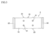
- FIG. 3 shows a plan view of each heat transfer tube 2
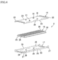
- FIG. 4 is an exploded view showing component parts of each heat transfer tube 2.
- Each heat transfer tube 2 comprises an upper case 16, a lower case 17 and a radiating fin 18, all of which are assembled together to form the heat transfer tube 2.
- the upper case 16 is in a shape of a flat halved quadrangular prism with a rectangular U-shaped cross section, and is made of stamped sheet metal (a sheet of stainless steel subjected to presswork), with a substantially rectangular top plate 19 and sidewalls 20 extending downward from left and right sides of the top plate 19 in a direction perpendicular to the top plate 19.
- stamped sheet metal a sheet of stainless steel subjected to presswork
- On the outer surface of the top plate 19 four shortened cylindrical projections 21 protruding upward with the same length are provided. These four projections 21 are arranged regularly such that the positions of the projections 21 coincide with the vertices of an imaginary rectangle.
- the shape of each projection 21 is substantially the same as those of the projections 10 on the upper outer case 4 and the projections 14 on the lower outer case 5.
- Bulged portions 22 protruding outward with the same length as that of each projection 21 are formed at the front and rear edges of the top plate 19 and the sidewalls 20.
- the projections 21 are arranged in a way similar to that in which the projections 10 on the upper outer case 4 and the projections 14 on the lower outer case 5 are arranged. Additionally, bulged stopper portions 23 are formed at two spots, front and rear, of each sidewall 20 so that the upper case 16 will not be misaligned with the lower case 17 when the upper case 16 is overlaid on the lower case 17.
- the lower case 17 similar to the upper case 16, is in a shape of a flat halved quadrangular prism with a rectangular U-shaped cross section, and is made of stamped sheet metal (a sheet of stainless steel subjected to presswork), with a substantially rectangular bottom plate 24 and sidewalls 25 extending upward from left and right sides of the bottom plate 24 in a direction perpendicular to the bottom plate 24.
- the spacing between the sidewalls 25 of the lower case 17 is slightly narrower than the spacing between the sidewalls 20 of the upper case 16.
- each projection 26 is arranged regularly such that the positions of the projections 26 correspond to the positions of the projections 21 on the upper case 16.
- the shape of each projection 26 is substantially the same as those of the projections 21 on the upper case 16, the projections 10 on the upper outer case 4 and the projections 14 on the lower outer case 5.
- Bulged portions 27 protruding outward with the same length as that of each projection 26 are formed at the front and rear edges of the bottom plate 24 and the sidewalls 25.
- bulged stopper portions 33 are formed at two spots, front and rear, of each sidewall 25 so that the bulged stopper portions 33 are aligned with the bulged stopper portions 23 of the upper case 16 when the upper case 16 is overlaid on the lower case 17.
- the radiating fin 18 is shaped generally like a flat plate having streaks or corrugation composed of a number of alternate grooves 28 and ridges 29 continuously arranged laterally, and is made of stamped sheet metal (a sheet of stainless steel subjected to presswork). On each of the grooves 28 and the ridges 29, a number of protruding pieces (not shown) for enhancing the efficiency of heat transfer are provided which protrude inwardly.
- each of the heat transfer tubes 2 is formed by assembling the upper case 16, the lower case 17 and the radiating fin 18, then, a heat transfer tube stack 30 is formed by stacking and temporarily holding the thus-formed heat transfer tubes 2, and the casing 3 with the heat transfer tube stack 30 stored therein is formed by welding (brazing) the upper outer case 4 and the lower outer case 5 together while welding (blazing) the assembled component parts of the heat transfer tube stack 30.
- each heat transfer tube 2 In order to assemble each heat transfer tube 2, first, a joint inhibitor (e . g ., an agent made of acrylic or urethane resin) is applied, with a predetermined thickness (0.1 ⁇ m to 100 ⁇ m), to the surfaces of the projections 21 on the upper case 16 and the projections 26 on the lower case 17 of each heat transfer tube 2. Next, the radiating fin 18 of which the bottom surfaces of the grooves 28 and the top surfaces of the ridges 29 are coated with a brazing material such as copper, nickel, etc. is put on the bottom plate 24 of the lower case 17, and the upper case 16 is fitted on the lower case 17 in such a manner that the sidewalls 20 of the upper case 16 are located on the outsides of the sidewalls 25 of the lower case 17.
- a joint inhibitor e . g ., an agent made of acrylic or urethane resin
- each of the heat transfer tubes 2 is assembled from component parts into an integral unit. Thereafter, the heat transfer tubes 2 are stacked and temporarily held to form the heat transfer tube stack 30. When the heat transfer tubes 2 are stacked, a brazing material is applied to the outsides of the bulged portions 22 of the upper case 16 and the bulged portions 27 of the lower case 17.
- the upper outer case 4 and the lower outer case 5 are welded (brazed) to form the casing 3, in which the heat transfer tube stack 30 is incorporated.
- a joint inhibitor as applied to the projections 21 on the upper case 16 and the projections 26 on the lower case 17 is applied to the surfaces of the projections 10 on the upper outer case 4 and the projections 14 on the lower outer case 5.
- the heat transfer tube stack 30 is placed inside the lower outer case 5, and the upper outer case 4 is fitted in lower outer case 5 in such a manner that the side plates 9 of the upper outer case 4 are located on the insides of the side plates 13 of the lower outer case 5.
- a brazing material is then applied between each side plate 9 of the upper outer case 4 and the corresponding side plate 13 of the lower outer case 5, whereby the casing 3 is assembled from component parts into an integral unit with the heat transfer tube stack 30 being incorporated inside the casing 3.
- the introduction pipe 6 having a brazing material applied to its connecting end is fitted to the joint hole 11 provided in one of the side plates 9 of the upper outer case 4, and the discharge pipe 7 having a brazing material applied to its connecting end is fitted to the joint hole 15 provided in one of the side plates 13 of the lower outer case 5. In this way, the preliminary assembly of the multitubular heat exchanger 1 is completed.
- the thus-tentatively assembled multitubular heat exchanger 1 is placed in a furnace and left in the reducing atmosphere at a predetermined temperature for a predetermined period of time, and then cooled for a predetermined period of time, so that the brazing materials applied to the respective component parts are molten and solidified (brazing step).
- brazing step in each of the heat transfer tubes 2, the upper case 16, the lower case 17 and the radiating fin 18 are welded together.
- each bulged portion 27 of the lower case 17 of one (first) heat transfer tube 2 located on top of another (second heat transfer tube 2) and the corresponding bulged portion 22 of the upper case 16 of the second transfer tube 2 located directly under the first heat transfer tube 2 are welded together.
- each bulged portion 22 of the upper case 16 of the uppermost heat transfer tube 2 and each bulged portion 27 of the lower case 17 of the lowermost heat transfer tube 2 are welded to the inner surface of the upper outer case 4 and the inner surface of the lower outer case 5, respectively.
- the introduction pipe 6 and the discharge pipe 7 are welded to the side plate 9 of the upper outer case 4 and the side plate 13 of the lower outer case 5, respectively. Consequently, the heat transfer tube stack 30 is enclosed inside the casing 3 in a gastight state.
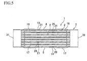
- pairs of the corresponding projections provided on adjacent heat transfer tubes 2 i . e ., each projection 26 on the lower case 17 of one heat transfer tube 2 located on top of another heat transfer tube 2 and a corresponding projection 21 on the upper case 16 of the latter heat transfer tube 2 located under the former heat transfer tube 2 are located adjacent to each other; the projections 21 on the upper case 16 of the uppermost heat transfer tube 2 and the corresponding projections 10 on the upper outer case 4 of the casing 3, as well as the projections 26 on the lower case 17 of the lowermost heat transfer tube 2 and the corresponding projections 14 on the lower outer case 5 of the casing 3, are located adjacent to each other, respectively ( see FIG. 5 ).
- a medium (e . g ., exhaust gas) introduced from an introduction port 31 provided at a front end of the casing 3 flows through the insides of the heat transfer tubes 2 which make up the heat transfer tube stack 30, and is discharged through a discharge port 32 provided at a rear end of the casing 3 to the outside.
- a medium (e . g ., cooling water) introduced through the introduction pipe 6 flows through spaces between the casing 3 and the heat transfer tube stack 30 and spaces among the heat transfer tubes which make up the heat transfer tube stack 30, and is discharged through the discharge pipe 7 to the outside.
- the multitubular heat exchanger 1 may be used in the exhaust gas recirculation or EGR system provided in an automobile, wherein part of exhaust gas is introduced from an exhaust manifold of the automobile into the multitubular heat exchanger 1 is cooled to a predetermined temperature so that the exhaust gas thus cooled (the so-called EGR gas) can be discharged through an EGR valve to the intake manifold.
- the multitubular heat exchanger 1 is configured, as described above, such that a plurality of projections (projections 21 and projections 26) are provided dispersedly on an outer surface of each of the heat transfer tubes 2 in predetermined positions, and a plurality of projections (projections 10 and projections 14) are provided dispersedly on an inner surface of the casing 3 in positions corresponding to the predetermined positions, and that the projections (projections 10 and projections 14) of the casing 3 are not joined to the projections (projections 21 and projections 26, respectively) of the heat transfer tubes 2, and the projections (projections 21 and projections 26) of the heat transfer tubes 2 are not joined to the projections (projections 26 and projections 21, respectively) of the adjacent heat transfer tubes 2. Therefore, the casing 3 and the heat transfer tubes 2 of the multitubular heat exchanger 1 is impervious to being damaged by continuously receiving the shocks such as the vibrations transmitted during the operation of the engine, or the like, over a long period of time.
- the multitubular heat exchanger 1 is configured such that a carbonized material is interposed between each of the projections (projections 10 on upper outer case 4; projections 14 on lower outer case 5) of the casing 3 and the corresponding projection (projections 21 on upper case 16; projections 26 on lower case 17) of the heat transfer tubes 2, and between each projection of the heat transfer tubes 2 and the corresponding projection of the adjacent heat transfer tubes 2 (projections 26 on lower case 17 of heat transfer tubes 2 on top of adjacent heat transfer tubes 2 and corresponding projections 21 on upper case 16 of those adjacent heat transfer tubes 2). Therefore, the adjacent projections are isolated from each other without fail, and thus the damage to the casing 3 and the heat transfer tubes 2 can be prevented more effectively.
- the material of the heat transfer tubes and the casing in a multitubular heat exchanger according to the present invention is not limited to the stainless steel as in the exemplary embodiment described above, but all or part of the heat transfer tubes and the casing may be made of any other metal.
- the number of the heat transfer tubes making up the heat transfer tube stack in a multitubular heat exchanger according to the present invention is not limited to seven as in the exemplary embodiment described above, but six or less or eight or more heat transfer tubes may be stacked to form a heat transfer tube stack incorporated in a casing of the multitubular heat exchanger.
- the number of projections provided on the upper and lower cases of the heat transfer tubes and on the upper and lower outer cases of the casing is not limited to four as in the exemplary embodiment described above, but three or less or five or more projections may be provided on each component.
- the shape of the projections is also not limited to that of a shortened cylinder or a truncated cone, but any modified shape may be applied such as the form of a shortened prism or a shortened elliptic cylinder or the like.
- arrangement of the projections may not be such that that the positions of the projections 10 coincide with the vertices of an imaginary rectangle, as in the exemplary embodiment described above; any other arrangement may be adopted, such as a lattice pattern and a staggered arrangement.
Landscapes
- Engineering & Computer Science (AREA)
- Mechanical Engineering (AREA)
- Physics & Mathematics (AREA)
- Thermal Sciences (AREA)
- General Engineering & Computer Science (AREA)
- Heat-Exchange Devices With Radiators And Conduit Assemblies (AREA)
Applications Claiming Priority (1)
| Application Number | Priority Date | Filing Date | Title |
|---|---|---|---|
| JP2009095101A JP4773541B2 (ja) | 2009-04-09 | 2009-04-09 | 多管式熱交換器 |
Publications (2)
| Publication Number | Publication Date |
|---|---|
| EP2239530A1 true EP2239530A1 (fr) | 2010-10-13 |
| EP2239530B1 EP2239530B1 (fr) | 2016-04-06 |
Family
ID=42334434
Family Applications (1)
| Application Number | Title | Priority Date | Filing Date |
|---|---|---|---|
| EP10159324.2A Not-in-force EP2239530B1 (fr) | 2009-04-09 | 2010-04-08 | Échangeur thermique à plusieurs tubes |
Country Status (2)
| Country | Link |
|---|---|
| EP (1) | EP2239530B1 (fr) |
| JP (1) | JP4773541B2 (fr) |
Cited By (2)
| Publication number | Priority date | Publication date | Assignee | Title |
|---|---|---|---|---|
| EP3054259A1 (fr) * | 2012-09-19 | 2016-08-10 | Benteler Automobiltechnik GmbH | Procede de fabrication d'un echangeur thermique |
| ES2676710A1 (es) * | 2017-01-23 | 2018-07-24 | Valeo Térmico, S. A. | Métodos para la fabricación de un conjunto formado por una unidad de conducción de gases y un filtro de partículas y para la fabricación de un intercambiador de calor para gases, y conjunto e intercambiador de calor fabricados según los métodos |
Families Citing this family (7)
| Publication number | Priority date | Publication date | Assignee | Title |
|---|---|---|---|---|
| JP2012137251A (ja) * | 2010-12-27 | 2012-07-19 | Maruyasu Industries Co Ltd | 多管式熱交換器 |
| JP6109473B2 (ja) * | 2011-11-30 | 2017-04-05 | 東京ラヂエーター製造株式会社 | Egrクーラ |
| JP6100459B2 (ja) * | 2011-12-19 | 2017-03-22 | フタバ産業株式会社 | 燃料電池用熱交換器 |
| DE102012211857A1 (de) | 2012-07-06 | 2014-01-09 | Behr Gmbh & Co. Kg | Wärmeübertrager |
| DE102014106807B4 (de) * | 2014-05-14 | 2017-12-21 | Benteler Automobiltechnik Gmbh | Abgaswärmetauscher aus Duplexstahl |
| JP2016080283A (ja) * | 2014-10-20 | 2016-05-16 | カルソニックカンセイ株式会社 | 熱交換チューブ |
| KR102335327B1 (ko) | 2017-04-28 | 2021-12-03 | 현대자동차 주식회사 | 수냉식 이지알 쿨러 |
Citations (6)
| Publication number | Priority date | Publication date | Assignee | Title |
|---|---|---|---|---|
| US20030010480A1 (en) * | 2001-07-16 | 2003-01-16 | Kazuhiro Shibagaki | Exhaust gas heat exchanger |
| US20030019616A1 (en) * | 2001-07-26 | 2003-01-30 | Takayuki Hayashi | Exhaust gas heat exchanger |
| US20040035916A1 (en) * | 2000-12-05 | 2004-02-26 | Morton Syslak | Process of connecting a heat exchanger tube to a manifold and tube especially made therefor |
| US20070000652A1 (en) * | 2005-06-30 | 2007-01-04 | Ayres Steven M | Heat exchanger with dimpled tube surfaces |
| JP2007225190A (ja) | 2006-02-23 | 2007-09-06 | Maruyasu Industries Co Ltd | 熱交換器 |
| WO2009016102A1 (fr) * | 2007-07-27 | 2009-02-05 | Valeo Termico S.A. | Echangeur de chaleur pour gaz, en particulier pour les gaz d'echappement d'un moteur |
Family Cites Families (4)
| Publication number | Priority date | Publication date | Assignee | Title |
|---|---|---|---|---|
| JP2001099587A (ja) * | 1999-09-30 | 2001-04-13 | Hisaka Works Ltd | プレート式熱交換器 |
| JP4392218B2 (ja) * | 2003-10-14 | 2009-12-24 | 株式会社マーレ フィルターシステムズ | 多板式熱交換器 |
| JP2006255746A (ja) * | 2005-03-16 | 2006-09-28 | Calsonic Kansei Corp | 積層型熱交換器の製造方法及び製造用治具 |
| JP2008304159A (ja) * | 2007-06-11 | 2008-12-18 | Denso Corp | 熱交換器の製造方法 |
-
2009
- 2009-04-09 JP JP2009095101A patent/JP4773541B2/ja active Active
-
2010
- 2010-04-08 EP EP10159324.2A patent/EP2239530B1/fr not_active Not-in-force
Patent Citations (6)
| Publication number | Priority date | Publication date | Assignee | Title |
|---|---|---|---|---|
| US20040035916A1 (en) * | 2000-12-05 | 2004-02-26 | Morton Syslak | Process of connecting a heat exchanger tube to a manifold and tube especially made therefor |
| US20030010480A1 (en) * | 2001-07-16 | 2003-01-16 | Kazuhiro Shibagaki | Exhaust gas heat exchanger |
| US20030019616A1 (en) * | 2001-07-26 | 2003-01-30 | Takayuki Hayashi | Exhaust gas heat exchanger |
| US20070000652A1 (en) * | 2005-06-30 | 2007-01-04 | Ayres Steven M | Heat exchanger with dimpled tube surfaces |
| JP2007225190A (ja) | 2006-02-23 | 2007-09-06 | Maruyasu Industries Co Ltd | 熱交換器 |
| WO2009016102A1 (fr) * | 2007-07-27 | 2009-02-05 | Valeo Termico S.A. | Echangeur de chaleur pour gaz, en particulier pour les gaz d'echappement d'un moteur |
Cited By (2)
| Publication number | Priority date | Publication date | Assignee | Title |
|---|---|---|---|---|
| EP3054259A1 (fr) * | 2012-09-19 | 2016-08-10 | Benteler Automobiltechnik GmbH | Procede de fabrication d'un echangeur thermique |
| ES2676710A1 (es) * | 2017-01-23 | 2018-07-24 | Valeo Térmico, S. A. | Métodos para la fabricación de un conjunto formado por una unidad de conducción de gases y un filtro de partículas y para la fabricación de un intercambiador de calor para gases, y conjunto e intercambiador de calor fabricados según los métodos |
Also Published As
| Publication number | Publication date |
|---|---|
| EP2239530B1 (fr) | 2016-04-06 |
| JP2010243125A (ja) | 2010-10-28 |
| JP4773541B2 (ja) | 2011-09-14 |
Similar Documents
| Publication | Publication Date | Title |
|---|---|---|
| EP2239530B1 (fr) | Échangeur thermique à plusieurs tubes | |
| US8656988B1 (en) | External reinforcement of connections between header tanks and tubes in heat exchangers | |
| US8074708B2 (en) | Heat exchanger | |
| US20070131404A1 (en) | Heat exchanger | |
| JP5029166B2 (ja) | 熱交換器 | |
| US20090065184A1 (en) | Heat exchanger | |
| US7048042B2 (en) | Heat exchanger, in particular exhaust gas heat exchanger for motor vehicles, and method for producing same | |
| WO2006102736A1 (fr) | Echangeur thermique a tubes empiles | |
| US20060144579A1 (en) | Heat exchanger | |
| US20070000657A1 (en) | Heat exchanger | |
| CN100425937C (zh) | 热交换器 | |
| US7389810B2 (en) | Displacement prevention device for the side plate of a heat exchanger | |
| US8136578B2 (en) | Heat exchanger for EGR-gas | |
| US11573058B2 (en) | Easily assembled heat exchanger | |
| US20070000652A1 (en) | Heat exchanger with dimpled tube surfaces | |
| JP2001174173A (ja) | 排気熱交換器 | |
| US20020134535A1 (en) | Heat exchanger | |
| EP1331462A2 (fr) | Echangeur de chaleur pour véhicule automobile | |
| JP7591894B2 (ja) | 積層型熱交換器 | |
| US20060048930A1 (en) | Heat exchanger | |
| US20070131400A1 (en) | Heat exchanger for gases, especially for engine exhaust gases | |
| JP6904154B2 (ja) | 熱交換器 | |
| JP6083272B2 (ja) | 熱交換器 | |
| JP4787511B2 (ja) | 熱交換器の接合構造及びその接合方法 | |
| JP2006064194A (ja) | 熱交換器 |
Legal Events
| Date | Code | Title | Description |
|---|---|---|---|
| PUAI | Public reference made under article 153(3) epc to a published international application that has entered the european phase |
Free format text: ORIGINAL CODE: 0009012 |
|
| AK | Designated contracting states |
Kind code of ref document: A1 Designated state(s): AT BE BG CH CY CZ DE DK EE ES FI FR GB GR HR HU IE IS IT LI LT LU LV MC MK MT NL NO PL PT RO SE SI SK SM TR |
|
| 17P | Request for examination filed |
Effective date: 20110413 |
|
| GRAP | Despatch of communication of intention to grant a patent |
Free format text: ORIGINAL CODE: EPIDOSNIGR1 |
|
| INTG | Intention to grant announced |
Effective date: 20151012 |
|
| GRAS | Grant fee paid |
Free format text: ORIGINAL CODE: EPIDOSNIGR3 |
|
| GRAA | (expected) grant |
Free format text: ORIGINAL CODE: 0009210 |
|
| AK | Designated contracting states |
Kind code of ref document: B1 Designated state(s): AT BE BG CH CY CZ DE DK EE ES FI FR GB GR HR HU IE IS IT LI LT LU LV MC MK MT NL NO PL PT RO SE SI SK SM TR |
|
| REG | Reference to a national code |
Ref country code: GB Ref legal event code: FG4D |
|
| REG | Reference to a national code |
Ref country code: AT Ref legal event code: REF Ref document number: 788280 Country of ref document: AT Kind code of ref document: T Effective date: 20160415 Ref country code: CH Ref legal event code: EP |
|
| REG | Reference to a national code |
Ref country code: IE Ref legal event code: FG4D |
|
| REG | Reference to a national code |
Ref country code: DE Ref legal event code: R096 Ref document number: 602010031981 Country of ref document: DE |
|
| REG | Reference to a national code |
Ref country code: FR Ref legal event code: PLFP Year of fee payment: 7 |
|
| REG | Reference to a national code |
Ref country code: LT Ref legal event code: MG4D Ref country code: NL Ref legal event code: MP Effective date: 20160406 |
|
| REG | Reference to a national code |
Ref country code: AT Ref legal event code: MK05 Ref document number: 788280 Country of ref document: AT Kind code of ref document: T Effective date: 20160406 |
|
| PG25 | Lapsed in a contracting state [announced via postgrant information from national office to epo] |
Ref country code: BE Free format text: LAPSE BECAUSE OF NON-PAYMENT OF DUE FEES Effective date: 20160430 |
|
| PG25 | Lapsed in a contracting state [announced via postgrant information from national office to epo] |
Ref country code: NL Free format text: LAPSE BECAUSE OF FAILURE TO SUBMIT A TRANSLATION OF THE DESCRIPTION OR TO PAY THE FEE WITHIN THE PRESCRIBED TIME-LIMIT Effective date: 20160406 |
|
| PG25 | Lapsed in a contracting state [announced via postgrant information from national office to epo] |
Ref country code: IS Free format text: LAPSE BECAUSE OF FAILURE TO SUBMIT A TRANSLATION OF THE DESCRIPTION OR TO PAY THE FEE WITHIN THE PRESCRIBED TIME-LIMIT Effective date: 20160806 Ref country code: PL Free format text: LAPSE BECAUSE OF FAILURE TO SUBMIT A TRANSLATION OF THE DESCRIPTION OR TO PAY THE FEE WITHIN THE PRESCRIBED TIME-LIMIT Effective date: 20160406 Ref country code: LT Free format text: LAPSE BECAUSE OF FAILURE TO SUBMIT A TRANSLATION OF THE DESCRIPTION OR TO PAY THE FEE WITHIN THE PRESCRIBED TIME-LIMIT Effective date: 20160406 Ref country code: FI Free format text: LAPSE BECAUSE OF FAILURE TO SUBMIT A TRANSLATION OF THE DESCRIPTION OR TO PAY THE FEE WITHIN THE PRESCRIBED TIME-LIMIT Effective date: 20160406 Ref country code: NO Free format text: LAPSE BECAUSE OF FAILURE TO SUBMIT A TRANSLATION OF THE DESCRIPTION OR TO PAY THE FEE WITHIN THE PRESCRIBED TIME-LIMIT Effective date: 20160706 |
|
| PG25 | Lapsed in a contracting state [announced via postgrant information from national office to epo] |
Ref country code: GR Free format text: LAPSE BECAUSE OF FAILURE TO SUBMIT A TRANSLATION OF THE DESCRIPTION OR TO PAY THE FEE WITHIN THE PRESCRIBED TIME-LIMIT Effective date: 20160707 Ref country code: SE Free format text: LAPSE BECAUSE OF FAILURE TO SUBMIT A TRANSLATION OF THE DESCRIPTION OR TO PAY THE FEE WITHIN THE PRESCRIBED TIME-LIMIT Effective date: 20160406 Ref country code: ES Free format text: LAPSE BECAUSE OF FAILURE TO SUBMIT A TRANSLATION OF THE DESCRIPTION OR TO PAY THE FEE WITHIN THE PRESCRIBED TIME-LIMIT Effective date: 20160406 Ref country code: LV Free format text: LAPSE BECAUSE OF FAILURE TO SUBMIT A TRANSLATION OF THE DESCRIPTION OR TO PAY THE FEE WITHIN THE PRESCRIBED TIME-LIMIT Effective date: 20160406 Ref country code: AT Free format text: LAPSE BECAUSE OF FAILURE TO SUBMIT A TRANSLATION OF THE DESCRIPTION OR TO PAY THE FEE WITHIN THE PRESCRIBED TIME-LIMIT Effective date: 20160406 Ref country code: PT Free format text: LAPSE BECAUSE OF FAILURE TO SUBMIT A TRANSLATION OF THE DESCRIPTION OR TO PAY THE FEE WITHIN THE PRESCRIBED TIME-LIMIT Effective date: 20160808 Ref country code: HR Free format text: LAPSE BECAUSE OF FAILURE TO SUBMIT A TRANSLATION OF THE DESCRIPTION OR TO PAY THE FEE WITHIN THE PRESCRIBED TIME-LIMIT Effective date: 20160406 |
|
| REG | Reference to a national code |
Ref country code: CH Ref legal event code: PL |
|
| REG | Reference to a national code |
Ref country code: FR Ref legal event code: TP Owner name: MARUYASU INDUSTRIES CO., LTD., JP Effective date: 20161114 |
|
| PG25 | Lapsed in a contracting state [announced via postgrant information from national office to epo] |
Ref country code: IT Free format text: LAPSE BECAUSE OF FAILURE TO SUBMIT A TRANSLATION OF THE DESCRIPTION OR TO PAY THE FEE WITHIN THE PRESCRIBED TIME-LIMIT Effective date: 20160406 Ref country code: BE Free format text: LAPSE BECAUSE OF FAILURE TO SUBMIT A TRANSLATION OF THE DESCRIPTION OR TO PAY THE FEE WITHIN THE PRESCRIBED TIME-LIMIT Effective date: 20160406 |
|
| REG | Reference to a national code |
Ref country code: DE Ref legal event code: R097 Ref document number: 602010031981 Country of ref document: DE |
|
| REG | Reference to a national code |
Ref country code: IE Ref legal event code: MM4A |
|
| PG25 | Lapsed in a contracting state [announced via postgrant information from national office to epo] |
Ref country code: RO Free format text: LAPSE BECAUSE OF FAILURE TO SUBMIT A TRANSLATION OF THE DESCRIPTION OR TO PAY THE FEE WITHIN THE PRESCRIBED TIME-LIMIT Effective date: 20160406 Ref country code: MC Free format text: LAPSE BECAUSE OF FAILURE TO SUBMIT A TRANSLATION OF THE DESCRIPTION OR TO PAY THE FEE WITHIN THE PRESCRIBED TIME-LIMIT Effective date: 20160406 Ref country code: CH Free format text: LAPSE BECAUSE OF NON-PAYMENT OF DUE FEES Effective date: 20160430 Ref country code: LI Free format text: LAPSE BECAUSE OF NON-PAYMENT OF DUE FEES Effective date: 20160430 Ref country code: SK Free format text: LAPSE BECAUSE OF FAILURE TO SUBMIT A TRANSLATION OF THE DESCRIPTION OR TO PAY THE FEE WITHIN THE PRESCRIBED TIME-LIMIT Effective date: 20160406 Ref country code: DK Free format text: LAPSE BECAUSE OF FAILURE TO SUBMIT A TRANSLATION OF THE DESCRIPTION OR TO PAY THE FEE WITHIN THE PRESCRIBED TIME-LIMIT Effective date: 20160406 Ref country code: CZ Free format text: LAPSE BECAUSE OF FAILURE TO SUBMIT A TRANSLATION OF THE DESCRIPTION OR TO PAY THE FEE WITHIN THE PRESCRIBED TIME-LIMIT Effective date: 20160406 Ref country code: EE Free format text: LAPSE BECAUSE OF FAILURE TO SUBMIT A TRANSLATION OF THE DESCRIPTION OR TO PAY THE FEE WITHIN THE PRESCRIBED TIME-LIMIT Effective date: 20160406 |
|
| PLBE | No opposition filed within time limit |
Free format text: ORIGINAL CODE: 0009261 |
|
| STAA | Information on the status of an ep patent application or granted ep patent |
Free format text: STATUS: NO OPPOSITION FILED WITHIN TIME LIMIT |
|
| PG25 | Lapsed in a contracting state [announced via postgrant information from national office to epo] |
Ref country code: SM Free format text: LAPSE BECAUSE OF FAILURE TO SUBMIT A TRANSLATION OF THE DESCRIPTION OR TO PAY THE FEE WITHIN THE PRESCRIBED TIME-LIMIT Effective date: 20160406 |
|
| 26N | No opposition filed |
Effective date: 20170110 |
|
| GBPC | Gb: european patent ceased through non-payment of renewal fee |
Effective date: 20160706 |
|
| REG | Reference to a national code |
Ref country code: FR Ref legal event code: PLFP Year of fee payment: 8 |
|
| PG25 | Lapsed in a contracting state [announced via postgrant information from national office to epo] |
Ref country code: GB Free format text: LAPSE BECAUSE OF NON-PAYMENT OF DUE FEES Effective date: 20160706 Ref country code: SI Free format text: LAPSE BECAUSE OF FAILURE TO SUBMIT A TRANSLATION OF THE DESCRIPTION OR TO PAY THE FEE WITHIN THE PRESCRIBED TIME-LIMIT Effective date: 20160406 Ref country code: IE Free format text: LAPSE BECAUSE OF NON-PAYMENT OF DUE FEES Effective date: 20160408 |
|
| REG | Reference to a national code |
Ref country code: FR Ref legal event code: PLFP Year of fee payment: 9 |
|
| PG25 | Lapsed in a contracting state [announced via postgrant information from national office to epo] |
Ref country code: CY Free format text: LAPSE BECAUSE OF FAILURE TO SUBMIT A TRANSLATION OF THE DESCRIPTION OR TO PAY THE FEE WITHIN THE PRESCRIBED TIME-LIMIT Effective date: 20160406 Ref country code: HU Free format text: LAPSE BECAUSE OF FAILURE TO SUBMIT A TRANSLATION OF THE DESCRIPTION OR TO PAY THE FEE WITHIN THE PRESCRIBED TIME-LIMIT; INVALID AB INITIO Effective date: 20100408 |
|
| PG25 | Lapsed in a contracting state [announced via postgrant information from national office to epo] |
Ref country code: LU Free format text: LAPSE BECAUSE OF NON-PAYMENT OF DUE FEES Effective date: 20160408 Ref country code: MT Free format text: LAPSE BECAUSE OF NON-PAYMENT OF DUE FEES Effective date: 20160430 Ref country code: MK Free format text: LAPSE BECAUSE OF FAILURE TO SUBMIT A TRANSLATION OF THE DESCRIPTION OR TO PAY THE FEE WITHIN THE PRESCRIBED TIME-LIMIT Effective date: 20160406 Ref country code: TR Free format text: LAPSE BECAUSE OF FAILURE TO SUBMIT A TRANSLATION OF THE DESCRIPTION OR TO PAY THE FEE WITHIN THE PRESCRIBED TIME-LIMIT Effective date: 20160406 |
|
| PG25 | Lapsed in a contracting state [announced via postgrant information from national office to epo] |
Ref country code: BG Free format text: LAPSE BECAUSE OF FAILURE TO SUBMIT A TRANSLATION OF THE DESCRIPTION OR TO PAY THE FEE WITHIN THE PRESCRIBED TIME-LIMIT Effective date: 20160406 |
|
| REG | Reference to a national code |
Ref country code: DE Ref legal event code: R081 Ref document number: 602010031981 Country of ref document: DE Owner name: MARUYASU INDUSTRIES CO., LTD., NAGOYA-SHI, JP Free format text: FORMER OWNERS: HONDA MOTOR CO., LTD., TOKYO, JP; MARUYASU INDUSTRIES CO., LTD., NAGOYA-SHI, AICHI, JP |
|
| PGFP | Annual fee paid to national office [announced via postgrant information from national office to epo] |
Ref country code: DE Payment date: 20240424 Year of fee payment: 15 |
|
| PGFP | Annual fee paid to national office [announced via postgrant information from national office to epo] |
Ref country code: FR Payment date: 20240429 Year of fee payment: 15 |
|
| REG | Reference to a national code |
Ref country code: DE Ref legal event code: R119 Ref document number: 602010031981 Country of ref document: DE |
|
| PG25 | Lapsed in a contracting state [announced via postgrant information from national office to epo] |
Ref country code: DE Free format text: LAPSE BECAUSE OF NON-PAYMENT OF DUE FEES Effective date: 20251104 |
|
| PG25 | Lapsed in a contracting state [announced via postgrant information from national office to epo] |
Ref country code: FR Free format text: LAPSE BECAUSE OF NON-PAYMENT OF DUE FEES Effective date: 20250430 |