EP2239531A2 - Mit Dampf beheizbare Hohl-Walze - Google Patents
Mit Dampf beheizbare Hohl-Walze Download PDFInfo
- Publication number
- EP2239531A2 EP2239531A2 EP10158115A EP10158115A EP2239531A2 EP 2239531 A2 EP2239531 A2 EP 2239531A2 EP 10158115 A EP10158115 A EP 10158115A EP 10158115 A EP10158115 A EP 10158115A EP 2239531 A2 EP2239531 A2 EP 2239531A2
- Authority
- EP
- European Patent Office
- Prior art keywords
- hollow roller
- rotary
- longitudinal axis
- siphon tube
- wall
- Prior art date
- Legal status (The legal status is an assumption and is not a legal conclusion. Google has not performed a legal analysis and makes no representation as to the accuracy of the status listed.)
- Granted
Links
Images


Classifications
-
- F—MECHANICAL ENGINEERING; LIGHTING; HEATING; WEAPONS; BLASTING
- F28—HEAT EXCHANGE IN GENERAL
- F28F—DETAILS OF HEAT-EXCHANGE AND HEAT-TRANSFER APPARATUS, OF GENERAL APPLICATION
- F28F5/00—Elements specially adapted for movement
- F28F5/02—Rotary drums or rollers
-
- B—PERFORMING OPERATIONS; TRANSPORTING
- B31—MAKING ARTICLES OF PAPER, CARDBOARD OR MATERIAL WORKED IN A MANNER ANALOGOUS TO PAPER; WORKING PAPER, CARDBOARD OR MATERIAL WORKED IN A MANNER ANALOGOUS TO PAPER
- B31F—MECHANICAL WORKING OR DEFORMATION OF PAPER, CARDBOARD OR MATERIAL WORKED IN A MANNER ANALOGOUS TO PAPER
- B31F1/00—Mechanical deformation without removing material, e.g. in combination with laminating
- B31F1/20—Corrugating; Corrugating combined with laminating to other layers
- B31F1/24—Making webs in which the channel of each corrugation is transverse to the web feed
- B31F1/26—Making webs in which the channel of each corrugation is transverse to the web feed by interengaging toothed cylinders cylinder constructions
- B31F1/28—Making webs in which the channel of each corrugation is transverse to the web feed by interengaging toothed cylinders cylinder constructions combined with uniting the corrugated webs to flat webs ; Making double-faced corrugated cardboard
- B31F1/2845—Details, e.g. provisions for drying, moistening, pressing
- B31F1/285—Heating or drying equipment
Definitions
- the invention relates to a steam-heated hollow roller according to the preamble of claim 1.
- Such a heatable with steam hollow roller is used for example in the production of corrugated cardboard as a so-called corrugating roll, as it is known from EP 0 917 949 B1 (corresponding US 6,092,579 ) is known. Furthermore, such steam-heated hollow rollers are used as so-called preheating rollers in corrugated cardboard plants to preheat paper webs. Further areas of application are in other fields of technology; Such hollow rollers are regularly used for heating or heating materials guided in webs over them.
- steam usually saturated steam or superheated steam is blown into the inner hollow roll. It gives off its heat via the inner wall of the hollow roller to the jacket, wherein the water vapor condenses.
- the condensate collects due to the gravity and the centrifugal force of the rotating hollow roller on the inner wall.
- This condensate layer has an insulating effect and thus disturbs the heat transfer from the steam to the roller.
- a siphon tube is used, the suction opening is located in the vicinity of the inner wall of the hollow roller.
- the distance of the suction opening of the siphon tube from the inner wall of the hollow roller is crucial for the remaining amount of condensate in the interior space of the hollow roller.
- the suction opening loop in, so that the siphon pipe rests tightly against the inner wall with the result that condensate can not be extracted.
- the siphon tube consists of an outer, rigid support tube and a displaceably mounted therein, flexible insert tube, whereby the distance between the suction opening to the inner wall of the hollow roller is adjustable.
- the distance between the suction opening to the inner wall of the hollow roller is adjustable.
- the invention is therefore based on the object, a heatable with steam hollow roller of the generic type so that an exact adjustment of the distance between the suction opening and inner wall of the hollow roller is also possible during operation of the hollow roller.
- the rotary feedthrough is adjusted by a predetermined angle, whereby exactly the height of the gap between the suction opening and inner wall is determined.
- a corresponding display can be attached to the rotary passage.
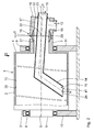
- the heatable hollow roller 1 shown in the drawing has a substantially cylindrical roller shell 2, which is closed vapor-tight by two end walls 3 and 4. At both end walls 3, 4 concentric with the central longitudinal axis 5 of the hollow roller 1 bearing pin 6, 7 are mounted, with rolling bearings 8, 9 in bearing blocks 10, 11th are stored. The hollow roller 1 is thus rotatably mounted. Such hollow rollers are rotatably drivable in the rule. Such a rotary drive, not shown in the drawing, can take place via the bearing journal 6 shown on the left in the drawing.
- the bearing pin 7 shown on the right in the drawing is hollow. Through it, according to the flow direction arrow 12 from a water-steam source, not shown, water vapor introduced into the hollow roller 1, whereby the roller shell 2 is heated. By this heating process and the associated heat release of the steam condenses the water vapor. The condensate is sucked from the lower region of the inner space 13 of the hollow roller 1 by means of a so-called siphon tube 14, wherein the suction direction is indicated by the flow-direction arrow 15. To the siphon tube 14, a vacuum source, not shown, is connected.
- This has a non-rotatable housing 17, which is arranged substantially concentric to the axis 5 and at its outer bottom 18, the siphon firmly connected to it Tube 14 carries.
- a steam supply nozzle 19 opens.
- the housing 17 of the rotary feedthrough 16 is rotatable by means of a spherical cap bearing 20 and pivotally connected to the bearing pin 7 relative to the axis 5.
- the bearing 20 has a cylindrical inner wall 21, so that on the one hand, the siphon tube 14 is also free from the spherical cap bearing 20 and further between the siphon tube 14 and the housing 17 and the bearing pin 7 a ring channel 22 to Supplying the water vapor from the nozzle 19 in the inner space 13 of the hollow roller 1 is given.
- the spherical cap bearing 20 may be made of a suitable plastic, so that it simultaneously abuts against the metal housing 17 on the one hand and the bearing pin 7 on the other hand, thus forming a vapor seal to the outside. Of course, however, other suitable seals may be provided.
- the main longitudinal axis 23 of the siphon tube 14 extends in alignment with the central longitudinal axis 5 of the hollow roller 1.
- the inner lower suction opening 24 has a minimum distance a to Inner wall 25 of the hollow roller 1.
- This angle ⁇ can be up to 5 °. In general, the angle will be ⁇ ⁇ 2 °.
- a manually operated pivoting adjustment device for the siphon tube 14 results from the Figures 3 and 4 ,
- the hollow bearing pin 7 bearing block 11 In stored on the hollow bearing pin 7 bearing block 11 are in a horizontal plane in which the central longitudinal axis 5 is located on both sides of the bearing pin 7 and the housing 17 bearing rods 26, 27 screwed.
- the housing 17 of the rotary bushing 16 On these bearing rods 26, 27, the housing 17 of the rotary bushing 16 is pivotally mounted by means of spherical pivot bearing 28 so that the previously with respect to the FIGS. 1 and 2 described pivoting movements can be performed.
- the two spherical pivot bearing 28 have a common horizontal pivot axis 29, which is aligned with the central pivot axis 30 of the ball dome bearing 20.
- the pivoting adjustment and -Fest ein the rotary passage 16 with siphon tube 14 is carried out in the embodiment of the FIGS. 1 to 4 by means of two pairs of adjusting screws 31, 32 which are mounted in corresponding laterally projecting abutments 33, 34 and abut against the bearing rods 26 and 27, respectively.
- the housing 17 of the rotary passage 16 from the in FIG. 1 position shown in the in FIG. 2 pivoted position shown and fixed there each. A backup of this position via counter-nuts 35th
- a linear drive 36 is provided in the form of a hydraulically or pneumatically actuated piston-cylinder drive, wherein the one lower end of the cylinder 37 is pivotally hinged to a stationary bearing 38, while the piston rod 39 is hinged in the lower region of the housing 17 by means of a bearing 40.
- the piston rod 39 is adjusted relative to the cylinder 37, which in turn the housing 17 of the rotary feedthrough 16 is adjusted in the manner described.
- hydraulic locking simultaneously fixing the housing 17 in this desired position.
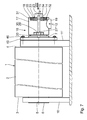
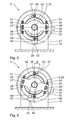
- the embodiment according to the FIGS. 6 to 9 is different from the one after the FIGS. 1 to 4 in that not only the gap 41 between the suction opening 24 of the siphon tube 14 and the inner wall 25 of the hollow roller 1 can be adjusted, but that the siphon tube 14 by means of a rotary-adjusting device to its main longitudinal axis 23 can be pivoted, so that the opening 24 is not located in the vertical longitudinal center plane 42 of the hollow roller 1, as in the embodiment of the FIGS. 1 to 4 or in the position according to FIG. 8 but in a thereto by a rotational angle ⁇ inclined longitudinal center plane 43 according to FIG. 9 , To make this possible, a ring bearing 44 is formed on the bearing block 11 ', on which a ring disc 45 is rotatably mounted.
- the ring disc 45 is - like the FIGS. 6 . 8 and 9 can be seen - held by two arranged in the vertical longitudinal center plane 42 screws 46 on the bearing block 11 '.
- the screws 46 pass through in the circumferential direction of the ring disc 45 extending longitudinal holes 47, so that - corresponding to the length of the long holes 47 - the ring disc 45 can be adjusted by the angle ⁇ in the circumferential direction, the angle between the Levels 42 and 43 corresponds.
- the bearing rods 26 "and 27" are attached to the ring disc 45 in this case. Otherwise the construction is like to FIGS. 1 to 4 described.
- the housing 17 of the rotary leadthrough 16 can be pivoted with the siphon tube 14 about its main longitudinal axis 23, so that the opening 24 is adjusted in the direction of rotation 48 of the hollow roller 1 can be.
- the mentioned condensate taken in the direction of rotation 48 becomes.
- An adjustment of the distance b of the suction opening 24 from the inner wall 25 of the hollow roller 1, that is, an adjustment of the width of the gap 41, also takes place here via the two pairs of adjusting screws 31,32.
Landscapes
- Engineering & Computer Science (AREA)
- Mechanical Engineering (AREA)
- Physics & Mathematics (AREA)
- Thermal Sciences (AREA)
- General Engineering & Computer Science (AREA)
- Rolls And Other Rotary Bodies (AREA)
- Paper (AREA)
- Heat-Exchange Devices With Radiators And Conduit Assemblies (AREA)
Abstract
Description
- Die Erfindung betrifft eine mit Dampf beheizbare Hohl-Walze nach dem Oberbegriff des Anspruches 1.
- Eine derart mit Dampf beheizbare Hohl-Walze wird beispielsweise bei der Herstellung von Wellpappe als sogenannte Riffelwalze eingesetzt, wie es aus der
EP 0 917 949 B1 (entsprechendUS 6 092 579 ) bekannt ist. Des Weiteren werden derartige mit Dampf beheizbare Hohl-Walzen als sogenannte Vorheiz-Walzen in Wellpappeanlagen eingesetzt, um Papierbahnen vorzuheizen. Weitere Einsatzgebiete befinden sich auf anderen Gebieten der Technik; regelmäßig werden solche Hohl-Walzen zum Erwärmen oder Erhitzen von in Bahnen über sie geführten Materialien eingesetzt. Hierbei wird einerseits Dampf, in der Regel Satt-Dampf oder überhitzter Dampf in die Innen-Hohl-Walze eingeblasen. Er gibt seine Wärme über die Innen-Wand der Hohl-Walze an deren Mantel ab, wobei der Wasser-Dampf kondensiert. Das Kondensat sammelt sich aufgrund der Schwerkraft sowie der Fliehkraft der sich drehenden Hohl-Walze an deren Innen-Wand. Diese Kondensat-Schicht wirkt isolierend und stört somit den Wärmeübergang vom Dampf auf die Walze. Zum Abführen des Kondensats wird ein Siphon-Rohr verwendet, dessen Absaug-Öffnung sich in der Nähe der Innen-Wand der Hohl-Walze befindet. Der Abstand der Absaug-Öffnung des Siphon-Rohres von der Innen-Wand der Hohl-Walze ist entscheidend für die im Innen-Raum der Hohl-Walze befindliche Restmenge an Kondensat. Außerdem kann beim Anliegen eines Siphon-Rohres an der Innen-Wand des Walzen-Mantels sich die Absaug-Öffnung einschleifen, so dass das Siphon-Rohr dicht an der Innen-Wand anliegt mit der Folge, dass Kondensat nicht mehr abgesaugt werden kann. - Bei einer derartigen aus der
EP 0 922 921 B1 bekannten mit Dampf beheizbaren Hohl-Walze besteht das Siphon-Rohr aus einem äußeren, starren Stützrohr und einem darin verschiebbar gelagerten, flexiblem Einsatzrohr, wodurch der Abstand der Absaug-Öffnung zur Innen-Wand der Hohl-Walze einstellbar ist. In der Praxis hat sich gezeigt, dass eine Einstellung des Abstandes der Absaug-Öffnung von der Innen-Wand der Hohl-Walze nur bei stehender Hohl-Walze, also in Betriebspausen, möglich ist. - Der Erfindung liegt daher die Aufgabe zugrunde, eine mit Dampf beheizbare Hohl-Walze der gattungsgemäßen Art so auszugestalten, dass eine exakte Einstellung des Abstandes zwischen Absaug-Öffnung und Innen-Wand der Hohl-Walze auch während des Betriebes der Hohl-Walze möglich ist.
- Diese Aufgabe wird gemäß der Erfindung durch die im Kennzeichnungsteil des Anspruches 1 angegebenen Merkmale gelöst. Da die Einstellung des Abstandes zwischen der Innen-Wand der Hohl-Walze und der Absaug-Öffnung des Siphon-Rohres durch eine Verschwenkung der außerhalb der Hohl-Walze liegenden, und sich nicht mit dieser drehenden Dreh-Durchführung vorgenommen wird, ist eine solche Verstellung auch während des oft hochtourigen Betriebs einer solchen Hohl-Walze ohne Weiteres möglich. Auch Nachjustierungen während des Betriebes sind möglich, ohne dass eine Fertigungs-Anlage, in der sich die beheizbare Hohl-Walze befindet, angehalten werden muss. Ein Anliegen des Siphon-Rohres an der Hohl-Walze und damit eine Einschleifen kann damit vermieden werden. Das Einstellung des Abstandes der Absaug-Öffnung von der Innen-Wand kann während des Betriebes in der Weise erfolgen, dass das Siphon-Rohr mit seiner Absaug-Öffnung gegen die Innen-Wand der Hohl-Walze angelegt wird. Dies kann akustisch oder durch Schwingungs-Messung erfasst werden. Anschließend wird die Dreh-Durchführung um einen vorgegebenen Winkel verstellt, womit exakt die Höhe des Spaltes zwischen Absaug-Öffnung und Innen-Wand festgelegt wird. Hierzu kann an der Dreh-Durchführung eine entsprechende Anzeige angebracht werden.
- Die Ansprüche 2 bis 4 geben vorteilhafte Ausgestaltungen der Dreh-Durchführung wieder.
- Die Ansprüche 5 bis 9 geben verschiedene vorteilhafte Ausgestaltungen einer Schwenk-Verstell-Einrichtung für die Dreh-Durchführung wieder.
- Vorteilhafte Weiterbildungen nach den Ansprüchen 10 bis 12 ermöglichen, dass die Absaug-Öffnung auch in Umfangs-Richtung, und zwar in Dreh-Richtung der Hohl-Walze verschwenkt und festgestellt werden kann, was im Hinblick auf die hohen Umfangsgeschwindigkeiten derartiger Hohl-Walzen in den entsprechenden Anlagen den Vorteil hat, dass Kondensat aufgrund der Mitnahme an der Innen-Wand der Hohl-Walze nicht am untersten Walzen-Grund, sondern weiter oben abgesaugt wird.
- Weitere Merkmale, Vorteile und Einzelheiten der Erfindung ergeben sich aus der nachfolgenden Beschreibung von Ausführungsbeispielen anhand der Zeichnung. Es zeigt:
- Fig. 1
- einen vertikalen Längsschnitt durch eine Hohl-Walze nach der Erfindung in einer Betriebsstellung mit an der Innen-Wand der Hohl-Walze befindlicher Absaug-Öffnung des Siphon-Rohres,
- Fig. 2
- die Hohl-Walze gemäß
Figur 1 mit maximal hoch geschwenktem Siphon-Rohr, - Fig. 3
- eine Draufsicht auf die Hohl-Walze nach den
Figuren 1 und2 entsprechend dem Sichtpfeil III in denFiguren 1 ,2 und4 , - Fig. 4
- eine Seiten-Längs-Ansicht der Hohl-Walze nach den
Figuren 1 bis 3 entsprechend dem Sichtpfeil IV inFigur 3 , - Fig. 5
- eine Hohl-Walze entsprechend der Darstellung in
Figur 4 mit gegenüber denFiguren 1 bis 4 geänderter Schwenk-Verstell-Einrichtung, - Fig. 6
- eine abgeänderte Ausführungsform der Hohl-Walze in einer Darstellung gemäß
Figur 1 mit einer Dreh-Verstell-Einrichtung, - Fig. 7
- die Hohl-Walze gemäß
Figur 6 in einer Darstellung gemäßFigur 4 , - Fig. 8
- eine Stirnansicht der Hohl-Walze nach den
Figuren 6 und7 entsprechend dem Sichtpfeil VIII in denFiguren 6 und7 mit unverdrehtem Siphon-Rohr, und - Fig. 9
- eine Darstellung entsprechend
Figur 8 mit in Dreh-Richtung der Hohl-Walze verdrehtem Siphon-Rohr. - Die in der Zeichnung dargestellte heizbare Hohl-Walze 1 weist einen im Wesentlichen zylindrischen Walzen-Mantel 2 auf, der durch zwei Stirnwände 3 und 4 dampfdicht abgeschlossen ist. An beiden Stirnwänden 3, 4 sind konzentrisch zur Mittel-Längs-Achse 5 der Hohl-Walze 1 Lager-Zapfen 6, 7 angebracht, die mit Wälz-Lagern 8, 9 in Lager-Böcken 10, 11 gelagert sind. Die Hohl-Walze 1 ist also drehbar gelagert. Derartige Hohl-Walzen sind in der Regel drehantreibbar. Ein solcher in der Zeichnung nicht dargestellter Drehantrieb kann über den in der Zeichnung links dargestellten Lager-Zapfen 6 erfolgen.
- Der in der Zeichnung rechts dargestellte Lager-Zapfen 7 ist hohl ausgebildet. Durch ihn wird entsprechend dem Strömungs-Richtungs-Pfeil 12 von einer nicht dargestellten Wasser-Dampf-Quelle kommender Wasser-Dampf in die Hohl-Walze 1 eingeführt, wodurch der Walzen-Mantel 2 beheizt wird. Durch diesen Heiz-Vorgang und die damit verbundene Wärmeabgabe des Dampfes kondensiert der Wasser-Dampf. Das Kondensat wird aus dem unteren Bereich des Innen-Raums 13 der Hohl-Walze 1 mittels eines sogenannten Siphon-Rohres 14 abgesaugt, wobei die Absaug-Richtung durch den Strömungs-Richtungs-Pfeil 15 angedeutet ist. An das Siphon-Rohr 14 ist eine nicht dargestellte Unterdruck-Quelle angeschlossen.
- Die Wasser-Dampf-Zuführung und die Kondensat-Absaugung erfolgt über eine sogenannte Dreh-Durchführung 16. Diese weist ein undrehbares Gehäuse 17 auf, das im Wesentlichen konzentrisch zur Achse 5 angeordnet ist und das an seinem außenliegenden Boden 18 das fest mit ihm verbundene Siphon-Rohr 14 trägt. In das Gehäuse 17 mündet ein Dampf-Zuführ-Stutzen 19 ein.
- Das Gehäuse 17 der Dreh-Durchführung 16 ist mittels eines Kugel-Kalotten-Lagers 20 drehbar und gegenüber der Achse 5 verschwenkbar mit dem Lager-Zapfen 7 verbunden. Das Lager 20 weist eine zylindrische Innen-Wand 21 auf, so dass zum einen das Siphon-Rohr 14 auch von dem Kugel-Kalotten-Lager 20 frei ist und weiterhin zwischen dem Siphon-Rohr 14 und dem Gehäuse 17 bzw. dem Lager-Zapfen 7 ein Ring-Kanal 22 zur Zuführung des Wasser-Dampfes vom Stutzen 19 in den Innen-Raum 13 der Hohl-Walze 1 gegeben ist. Das Kugel-Kalotten-Lager 20 kann aus einem geeigneten Kunststoff bestehen, so dass es gleichzeitig gegenüber dem jeweils aus Metall bestehenden Gehäuse 17 einerseits und dem Lager-Zapfen 7 andererseits anliegt und so eine Dampf-Dichtung nach außen bildet. Selbstverständlich können aber auch andere geeignete Dichtungen vorgesehen sein.
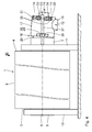
- Bei der Betriebsstellung gemäß
Figur 1 verläuft die Haupt-Längs-Achse 23 des Siphon-Rohres 14 fluchtend mit der Mittel-Längs-Achse 5 der Hohl-Walze 1. In dieser Position des Siphon-Rohrs 14 hat dessen innere untere Absaug-Öffnung 24 einen Minimal-Abstand a zur Innen-Wand 25 der Hohl-Walze 1. In der inFigur 2 dargestellten Lage des Siphon-Rohres 14 ist dessen Haupt-Längs-Achse 23 um einen Schwenk-Winkel α gegenüber der Mittel-Längs-Achse 5 verschwenkt, so dass die Absaug-Öffnung 24 einen größeren Abstand b zur Innen-Wand 25 hat. Dieser Winkel α kann bis zu 5° betragen. In der Regel wird der Winkel α ≤ 2° sein. - Eine manuell zu betätigende Schwenk-Verstell-Einrichtung für das Siphon-Rohr 14 ergibt sich aus den
Figuren 3 und4 . In an dem hohlen Lager-Zapfen 7 lagernden Lager-Bock 11 sind in einer horizontalen Ebene, in der sich auch die Mittel-Längs-Achse 5 befindet, beiderseits des Lager-Zapfens 7 und des Gehäuses 17 Lager-Stäbe 26, 27 geschraubt. Auf diesen Lager-Stäben 26, 27 ist das Gehäuse 17 der Dreh-Durchführung 16 mittels kugeliger Schwenk-Lager 28 schwenkbar gelagert, so dass die zuvor im Hinblick auf dieFiguren 1 und2 geschilderten Schwenkbewegungen ausgeführt werden können. Die beiden kugeligen Schwenk-Lager 28 haben eine gemeinsame horizontale Schwenk-Achse 29, die fluchtend mit der Mittel-Schwenk-Achse 30 des Kugel-Kalotten-Lagers 20 verläuft. - Die Schwenk-Verstellung und -Feststellung der Dreh-Durchführung 16 mit Siphon-Rohr 14 erfolgt bei dem Ausführungsbeispiel nach den
Figuren 1 bis 4 mittels zwei Paaren von Stell-Schrauben 31, 32, die in entsprechenden seitlich vorspringenden Widerlagern 33, 34 gelagert sind und gegen die Lager-Stäbe 26 bzw. 27 anliegen. Durch entsprechendes Herausdrehen der oberen Stell-Schrauben 31 aus den entsprechenden oberen Widerlagern 33 und entsprechendes Hineinschrauben der jeweiligen unteren Stell-Schraube 32 in das entsprechende untere Widerlager 34 wird das Gehäuse 17 der Dreh-Durchführung 16 aus der inFigur 1 dargestellten Position in die inFigur 2 dargestellte Position verschwenkt und dort jeweils fixiert. Eine Sicherung dieser Position erfolgt über Konter-Muttern 35. - Bei der abgewandelten Ausführungsform nach
Figur 5 ist eine motorische Verstellung und Feststellung der Dreh-Durchführung 16 möglich. Bei dieser Schwenk-Verstell-Einrichtung weisen die Lager-Stäbe 26', 27' nur die kugeligen Schwenk-Lager 28 auf. Anstelle der Stell-Schrauben 31, 32 ist ein Linear-Antrieb 36 in Form eines hydraulisch oder pneumatisch beaufschlagbaren Kolben-Zylinder-Antriebs vorgesehen, bei dem das eine untere Ende des Zylinders 37 schwenkbar an einem ortsfesten Lager 38 angelenkt ist, während die Kolbenstange 39 im unteren Bereich des Gehäuses 17 mittels eines Lagers 40 angelenkt ist. Durch entsprechende Beaufschlagung des Zylinders 37 mit Druckfluid wird die Kolbenstange 39 relativ zum Zylinder 37 verstellt, wodurch wiederum das Gehäuse 17 der Dreh-Durchführung 16 in der geschilderten Weise verstellt wird. Durch hydraulische Verriegelung erfolgt gleichzeitig eine Festsetzung des Gehäuses 17 in dieser gewünschten Position. - Die Ausführungsform nach den
Figuren 6 bis 9 unterscheidet sich von der nach denFiguren 1 bis 4 dadurch, dass nicht nur der Spalt 41 zwischen der Absaug-Öffnung 24 des Siphon-Rohres 14 und der Innen-Wand 25 der Hohl-Walze 1 verstellt werden kann, sondern dass auch das Siphon-Rohr 14 mittels einer Dreh-Verstell-Einrichtung um seine Haupt-Längs-Achse 23 verschwenkt werden kann, so dass die Öffnung 24 sich nicht in der vertikalen Längs-Mittel-Ebene 42 der Hohl-Walze 1 befindet, wie beim Ausführungsbeispiel nach denFiguren 1 bis 4 oder bei der Stellung gemäßFigur 8 , sondern in einer hierzu um einen Dreh-Winkel β geneigten Längs-Mittel-Ebene 43 gemäßFigur 9 . Um dies zu ermöglichen, ist am Lager-Bock 11' ein Ring-Lager 44 ausgebildet, auf dem eine Ring-Scheibe 45 drehbar gelagert ist. Die Ring-Scheibe 45 ist - wie dieFiguren 6 ,8 und 9 erkennen lassen - mittels zwei in der vertikalen Längs-Mittel-Ebene 42 angeordneten Schrauben 46 am Lager-Bock 11' gehalten. Die Schrauben 46 durchsetzen sich in Umfangsrichtung der Ring-Scheibe 45 erstreckende Lang-Löcher 47, so dass - entsprechend der Länge der Lang-Löcher 47 - die Ring-Scheibe 45 um den Winkel β in Umfangsrichtung verstellt werden kann, der dem Winkel zwischen den Ebenen 42 und 43 entspricht. Die Lager-Stäbe 26" und 27" sind in diesem Fall an der Ring-Scheibe 45 befestigt. Ansonsten ist der Aufbau wie zu denFiguren 1 bis 4 beschrieben. - Durch die Verstellmöglichkeit der Ring-Scheibe 45 kann das Gehäuse 17 der Dreh-Durchführung 16 mit dem Siphon-Rohr 14 um seine Haupt-Längs-Achse 23 verschwenkt werden, so dass die Öffnung 24 in Dreh-Richtung 48 der Hohl-Walze 1 verstellt werden kann. Hierdurch kann - insbesondere bei hochtourig angetriebenen Hohl-Walzen 1 - berücksichtigt werden, dass das erwähnte Kondensat in Dreh-Richtung 48 mitgenommen wird. Eine Einstellung des Abstandes b der Absaug-Öffnung 24 von der Innen-Wand 25 der Hohl-Walze 1, das heißt eine Einstellung der Weite des Spaltes 41, erfolgt auch hierbei über die beiden Paare von Stell-Schrauben 31,32.
Claims (12)
- Mit Dampf beheizbare Hohl-Walze (1),- die einen Walzen-Mantel (2) mit einer Innen-Wand (25), zwei Stirnwände (3, 4), eine Mittel-Längs-Achse (5) und einen Innen-Raum (13) aufweist,- die drehbar gelagert ist,- die einen koaxial zur Mittel-Längs-Achse (5) in den Innen-Raum (13) einmündenden Dampf-Zuführ-Kanal aufweist und- die ein koaxial zur Mittel-Längs-Achse (5) in den Innen-Raum (13) einmündendes Siphon-Rohr (14) mit einer benachbart zur Innen-Wand (25) befindlichen Absaug-Öffnung (24) aufweist,dadurch gekennzeichnet,
dass das starr ausgebildete Siphon-Rohr (14) in einer Dreh-Durchführung (16) gehalten ist, die relativ zur Mittel-Längs-Achse (5) derart um einen Schwenk-Winkel α verschwenkbar ist, dass der Abstand b der Absaug-Öffnung (24) von der Innen-Wand (25) einstellbar ist. - Hohl-Walze (1) nach Anspruch 1, dadurch gekennzeichnet,
dass die der Dreh-Durchführung (16) benachbarte Stirnwand (4) mit einem hohlen Lager-Zapfen (7) versehen ist, der mit einem Gehäuse (17) der Dreh-Durchführung (16) drehbar und um den Schwenk-Winkel α verschwenkbar und dampfdicht verbunden ist. - Hohl-Walze (1) nach Anspruch 1 oder 2, dadurch gekennzeichnet, dass die Dreh-Durchführung (16) einen Dampf-Zuführ-Stutzen (19) aufweist, der in den das Siphon-Rohr (14) umgebenden als Ring-Kanal (22) ausgebildeten Dampf-Zuführ-Kanal übergeht.
- Hohl-Walze (1) nach einem der Ansprüche 1 bis 3, dadurch gekennzeichnet,
dass die Dreh-Durchführung (16) auf Schwenk-Lagern (28) gelagert ist. - Hohl-Walze (1) nach einem der Ansprüche 1 bis 4, dadurch gekennzeichnet,
dass eine Schwenk-Verstell-Einrichtung vorgesehen ist zur Schwenk-Verstellung der Dreh-Durchführung (16) mit dem Siphon-Rohr (14). - Hohl-Walze (1) nach Anspruch 5, dadurch gekennzeichnet,
dass die Schwenk-Lager (28) ortsfest angeordnet sind. - Hohl-Walze (1) nach Anspruch 4, dadurch gekennzeichnet,
dass die Schwenk-Verstellung-Einrichtung manuell betätigbar ausgebildet ist. - Hohl-Walze (1) nach Anspruch 7, dadurch gekennzeichnet,
dass die Schwenk-Verstell-Einrichtung Verstell-Schrauben (31, 32) zur Schwenk-Verstellung aufweist. - Hohl-Walze (1) nach Anspruch 4, dadurch gekennzeichnet,
dass die Schwenk-Verstellung-Einrichtung motorisch betätigbar ausgebildet ist. - Hohl-Walze (1) nach einem der Ansprüche 1 bis 9, dadurch gekennzeichnet,
dass die Dreh-Durchführung (16) mit Siphon-Rohr (14) um die Mittel-Längs-Achse (5) um einen Dreh-Winkel β verstellbar ist. - Hohl-Walze (1) nach Anspruch 10 und einem der Ansprüche 1 bis 9, dadurch gekennzeichnet,
dass die Dreh-Durchführung (16) an einer Ring-Scheibe (45) gelagert ist, die drehbar und feststellbar abgestützt ist. - Hohl-Walze (1) nach den Ansprüchen 5 und 11, dadurch gekennzeichnet,
dass die Schwenk-Lager (28) an der Ring-Scheibe (45) angebracht sind.
Applications Claiming Priority (1)
| Application Number | Priority Date | Filing Date | Title |
|---|---|---|---|
| DE102009016677A DE102009016677A1 (de) | 2009-04-07 | 2009-04-07 | Mit Dampf beheizbare Hohl-Walze |
Publications (3)
| Publication Number | Publication Date |
|---|---|
| EP2239531A2 true EP2239531A2 (de) | 2010-10-13 |
| EP2239531A3 EP2239531A3 (de) | 2013-10-16 |
| EP2239531B1 EP2239531B1 (de) | 2016-09-07 |
Family
ID=42352254
Family Applications (1)
| Application Number | Title | Priority Date | Filing Date |
|---|---|---|---|
| EP10158115.5A Active EP2239531B1 (de) | 2009-04-07 | 2010-03-29 | Mit Dampf beheizbare Hohl-Walze |
Country Status (4)
| Country | Link |
|---|---|
| US (1) | US8523747B2 (de) |
| EP (1) | EP2239531B1 (de) |
| DE (1) | DE102009016677A1 (de) |
| ES (1) | ES2594777T3 (de) |
Families Citing this family (1)
| Publication number | Priority date | Publication date | Assignee | Title |
|---|---|---|---|---|
| DE102019008884A1 (de) * | 2019-12-19 | 2021-06-24 | Singulus Technologies Ag | Behandlungsanlage, Antriebseinheit für eine Behandlungsanlage und Verwendung der Behandlungsanlage |
Citations (2)
| Publication number | Priority date | Publication date | Assignee | Title |
|---|---|---|---|---|
| US6092579A (en) | 1997-11-19 | 2000-07-25 | Bhs Corrugated Maschinen-Und Anlagenbau Gmbh | Machine for the production of an at least single-face lined web of corrugated board |
| EP0922921B1 (de) | 1997-12-11 | 2003-02-05 | BHS CORRUGATED MASCHINEN- UND ANLAGENBAU GmbH | Dampfbeheizte Walze, insbesondere für Wellpappemaschinen |
Family Cites Families (10)
| Publication number | Priority date | Publication date | Assignee | Title |
|---|---|---|---|---|
| US2297094A (en) * | 1940-07-05 | 1942-09-29 | Armstrong Machine Works | Drainage device for web drying machines |
| US2875527A (en) * | 1957-04-24 | 1959-03-03 | Beloit Iron Works | Dryer stationary syphon |
| NL226668A (de) * | 1957-05-07 | |||
| DE2553447A1 (de) * | 1975-11-28 | 1977-06-02 | Kleinewefers Ind Co Gmbh | Syphon-kniegelenk |
| US4498249A (en) * | 1982-09-30 | 1985-02-12 | Beloit Corporation | Dryer stationary syphon adjustment mechanism |
| GB8824808D0 (en) * | 1988-10-22 | 1988-11-30 | Simon Container Mach Ltd | Heated roll |
| US5533569A (en) * | 1995-04-24 | 1996-07-09 | The Johnson Corporation | Stationary syphon system for rotating heat exchanger rolls |
| FI98653C (fi) * | 1995-08-29 | 1997-07-25 | Valmet Corp | Lauhteenpoistolaitteisto ja menetelmä lauhteen poiston säädössä |
| DE19910125C2 (de) * | 1999-03-08 | 2001-03-08 | Friese Gmbh & Co Kg | Vorrichtung zur Kondensatableitung aus dampfbeheizten Walzen |
| US6203072B1 (en) * | 1999-08-30 | 2001-03-20 | The Johnson Corporation | Corrugating joint and syphon system |
-
2009
- 2009-04-07 DE DE102009016677A patent/DE102009016677A1/de not_active Withdrawn
-
2010
- 2010-03-29 EP EP10158115.5A patent/EP2239531B1/de active Active
- 2010-03-29 ES ES10158115.5T patent/ES2594777T3/es active Active
- 2010-04-07 US US12/755,723 patent/US8523747B2/en not_active Expired - Fee Related
Patent Citations (3)
| Publication number | Priority date | Publication date | Assignee | Title |
|---|---|---|---|---|
| US6092579A (en) | 1997-11-19 | 2000-07-25 | Bhs Corrugated Maschinen-Und Anlagenbau Gmbh | Machine for the production of an at least single-face lined web of corrugated board |
| EP0917949B1 (de) | 1997-11-19 | 2002-06-05 | BHS Corrugated Maschinen- und Anlagenbau GmbH | Maschine zur Herstellung einer mindestens einseitig kaschierten Wellpappebahn |
| EP0922921B1 (de) | 1997-12-11 | 2003-02-05 | BHS CORRUGATED MASCHINEN- UND ANLAGENBAU GmbH | Dampfbeheizte Walze, insbesondere für Wellpappemaschinen |
Also Published As
| Publication number | Publication date |
|---|---|
| EP2239531B1 (de) | 2016-09-07 |
| DE102009016677A1 (de) | 2010-10-21 |
| ES2594777T3 (es) | 2016-12-22 |
| US8523747B2 (en) | 2013-09-03 |
| EP2239531A3 (de) | 2013-10-16 |
| US20100255971A1 (en) | 2010-10-07 |
Similar Documents
| Publication | Publication Date | Title |
|---|---|---|
| AT511975B1 (de) | Transfersaugwalze zum überführen einer materialbahn | |
| DE1511217B1 (de) | Trockenzylinder fuer Papiermaschinen | |
| EP3581291B1 (de) | Blechbiegemaschine mit veränderbarer walzengeometrie | |
| EP2239531B1 (de) | Mit Dampf beheizbare Hohl-Walze | |
| AT392661B (de) | Presswalze, deren durchbiegung einstellbar ist | |
| DE1292957B (de) | Anordnung an hohlen Druckwalzen | |
| DE4030190C2 (de) | Verfahren zur Reduzierung des Leistungsverbrauchs einer durchbiegungskompensierten Walze und eine durchbiegungskompensierte Walze | |
| DE3312396C2 (de) | Vorrichtung zum Zentrieren eines Bewehrungskorbs | |
| DE69714757T2 (de) | Entnahmewalze, breitstreckwalze oder dergleichen für bahnförmiges materal | |
| DE10023291A1 (de) | Beheizbare oder kühlbare Walze zur Temperaturbehandlung von Materialbahnen, insbesondere zur Verwendung für Wellpappemaschinen | |
| DE1461126B1 (de) | Trockenzylinder fuer Papiermaschinen | |
| EP3874092B1 (de) | Breitstreckwalze | |
| DE549317C (de) | Verfahren, um auf einer Biegemaschine mit balliger Biegewalze zylindrisch gestaltete Werkstuecke zu erzielen | |
| DE4230920A1 (de) | Mit einem waermetraegermedium beaufschlagter trockenzylinder zur behandlung bahnfoermigen guts, insbesondere zur verwendung bei papiermaschinen | |
| DE1266119B (de) | Trockenzylinder fuer Papiermaschinen | |
| DE2139651B2 (de) | Behandlungsvorrichtung mit einer exzentrisch umlaufenden Arbeitstrommel | |
| EP2139671B1 (de) | Pressschnecke | |
| DE542982C (de) | Saugwalze | |
| EP1870179A2 (de) | Vorrichtung zum taktweisen Vorschieben eines Werkstoffbandes | |
| CH629675A5 (en) | Device for separating solid and liquid substances | |
| EP1389693B1 (de) | Temperierbare Walze und Verfahren zu ihrem Betrieb | |
| DE575808C (de) | Vorrichtung zur druckdichten Verbindung einer sich drehenden Rohrleitung und einer feststehenden Rohrleitung | |
| EP0134434B1 (de) | Walze mit hydraulisch anpassbarer Biegelinie | |
| DE19755045A1 (de) | Dampfbeheizte Walze, insbesondere für Wellpappenmaschinen | |
| DE2334436A1 (de) | Vier-walzen-blechbiegemaschine |
Legal Events
| Date | Code | Title | Description |
|---|---|---|---|
| PUAI | Public reference made under article 153(3) epc to a published international application that has entered the european phase |
Free format text: ORIGINAL CODE: 0009012 |
|
| AK | Designated contracting states |
Kind code of ref document: A2 Designated state(s): AT BE BG CH CY CZ DE DK EE ES FI FR GB GR HR HU IE IS IT LI LT LU LV MC MK MT NL NO PL PT RO SE SI SK SM TR |
|
| AX | Request for extension of the european patent |
Extension state: AL BA ME RS |
|
| RIN1 | Information on inventor provided before grant (corrected) |
Inventor name: TOBIES, HARALD Inventor name: HECKY, THOMAS |
|
| RIN1 | Information on inventor provided before grant (corrected) |
Inventor name: TOBIES, HARALD Inventor name: HECKY, THOMAS |
|
| PUAL | Search report despatched |
Free format text: ORIGINAL CODE: 0009013 |
|
| AK | Designated contracting states |
Kind code of ref document: A3 Designated state(s): AT BE BG CH CY CZ DE DK EE ES FI FR GB GR HR HU IE IS IT LI LT LU LV MC MK MT NL NO PL PT RO SE SI SK SM TR |
|
| AX | Request for extension of the european patent |
Extension state: AL BA ME RS |
|
| RIC1 | Information provided on ipc code assigned before grant |
Ipc: F28F 5/02 20060101AFI20130909BHEP |
|
| 17P | Request for examination filed |
Effective date: 20131023 |
|
| RBV | Designated contracting states (corrected) |
Designated state(s): AT BE BG CH CY CZ DE DK EE ES FI FR GB GR HR HU IE IS IT LI LT LU LV MC MK MT NL NO PL PT RO SE SI SK SM TR |
|
| GRAP | Despatch of communication of intention to grant a patent |
Free format text: ORIGINAL CODE: EPIDOSNIGR1 |
|
| INTG | Intention to grant announced |
Effective date: 20160506 |
|
| GRAS | Grant fee paid |
Free format text: ORIGINAL CODE: EPIDOSNIGR3 |
|
| GRAA | (expected) grant |
Free format text: ORIGINAL CODE: 0009210 |
|
| AK | Designated contracting states |
Kind code of ref document: B1 Designated state(s): AT BE BG CH CY CZ DE DK EE ES FI FR GB GR HR HU IE IS IT LI LT LU LV MC MK MT NL NO PL PT RO SE SI SK SM TR |
|
| REG | Reference to a national code |
Ref country code: GB Ref legal event code: FG4D Free format text: NOT ENGLISH |
|
| REG | Reference to a national code |
Ref country code: CH Ref legal event code: EP |
|
| REG | Reference to a national code |
Ref country code: IE Ref legal event code: FG4D Free format text: LANGUAGE OF EP DOCUMENT: GERMAN |
|
| REG | Reference to a national code |
Ref country code: AT Ref legal event code: REF Ref document number: 827256 Country of ref document: AT Kind code of ref document: T Effective date: 20161015 |
|
| REG | Reference to a national code |
Ref country code: DE Ref legal event code: R096 Ref document number: 502010012342 Country of ref document: DE |
|
| REG | Reference to a national code |
Ref country code: ES Ref legal event code: FG2A Ref document number: 2594777 Country of ref document: ES Kind code of ref document: T3 Effective date: 20161222 |
|
| REG | Reference to a national code |
Ref country code: LT Ref legal event code: MG4D |
|
| REG | Reference to a national code |
Ref country code: NL Ref legal event code: MP Effective date: 20160907 |
|
| PG25 | Lapsed in a contracting state [announced via postgrant information from national office to epo] |
Ref country code: HR Free format text: LAPSE BECAUSE OF FAILURE TO SUBMIT A TRANSLATION OF THE DESCRIPTION OR TO PAY THE FEE WITHIN THE PRESCRIBED TIME-LIMIT Effective date: 20160907 Ref country code: FI Free format text: LAPSE BECAUSE OF FAILURE TO SUBMIT A TRANSLATION OF THE DESCRIPTION OR TO PAY THE FEE WITHIN THE PRESCRIBED TIME-LIMIT Effective date: 20160907 Ref country code: LT Free format text: LAPSE BECAUSE OF FAILURE TO SUBMIT A TRANSLATION OF THE DESCRIPTION OR TO PAY THE FEE WITHIN THE PRESCRIBED TIME-LIMIT Effective date: 20160907 Ref country code: NO Free format text: LAPSE BECAUSE OF FAILURE TO SUBMIT A TRANSLATION OF THE DESCRIPTION OR TO PAY THE FEE WITHIN THE PRESCRIBED TIME-LIMIT Effective date: 20161207 |
|
| PG25 | Lapsed in a contracting state [announced via postgrant information from national office to epo] |
Ref country code: LV Free format text: LAPSE BECAUSE OF FAILURE TO SUBMIT A TRANSLATION OF THE DESCRIPTION OR TO PAY THE FEE WITHIN THE PRESCRIBED TIME-LIMIT Effective date: 20160907 Ref country code: NL Free format text: LAPSE BECAUSE OF FAILURE TO SUBMIT A TRANSLATION OF THE DESCRIPTION OR TO PAY THE FEE WITHIN THE PRESCRIBED TIME-LIMIT Effective date: 20160907 Ref country code: GR Free format text: LAPSE BECAUSE OF FAILURE TO SUBMIT A TRANSLATION OF THE DESCRIPTION OR TO PAY THE FEE WITHIN THE PRESCRIBED TIME-LIMIT Effective date: 20161208 Ref country code: SE Free format text: LAPSE BECAUSE OF FAILURE TO SUBMIT A TRANSLATION OF THE DESCRIPTION OR TO PAY THE FEE WITHIN THE PRESCRIBED TIME-LIMIT Effective date: 20160907 |
|
| REG | Reference to a national code |
Ref country code: FR Ref legal event code: PLFP Year of fee payment: 8 |
|
| PG25 | Lapsed in a contracting state [announced via postgrant information from national office to epo] |
Ref country code: RO Free format text: LAPSE BECAUSE OF FAILURE TO SUBMIT A TRANSLATION OF THE DESCRIPTION OR TO PAY THE FEE WITHIN THE PRESCRIBED TIME-LIMIT Effective date: 20160907 Ref country code: EE Free format text: LAPSE BECAUSE OF FAILURE TO SUBMIT A TRANSLATION OF THE DESCRIPTION OR TO PAY THE FEE WITHIN THE PRESCRIBED TIME-LIMIT Effective date: 20160907 |
|
| PG25 | Lapsed in a contracting state [announced via postgrant information from national office to epo] |
Ref country code: PT Free format text: LAPSE BECAUSE OF FAILURE TO SUBMIT A TRANSLATION OF THE DESCRIPTION OR TO PAY THE FEE WITHIN THE PRESCRIBED TIME-LIMIT Effective date: 20170109 Ref country code: IS Free format text: LAPSE BECAUSE OF FAILURE TO SUBMIT A TRANSLATION OF THE DESCRIPTION OR TO PAY THE FEE WITHIN THE PRESCRIBED TIME-LIMIT Effective date: 20170107 Ref country code: SM Free format text: LAPSE BECAUSE OF FAILURE TO SUBMIT A TRANSLATION OF THE DESCRIPTION OR TO PAY THE FEE WITHIN THE PRESCRIBED TIME-LIMIT Effective date: 20160907 Ref country code: BG Free format text: LAPSE BECAUSE OF FAILURE TO SUBMIT A TRANSLATION OF THE DESCRIPTION OR TO PAY THE FEE WITHIN THE PRESCRIBED TIME-LIMIT Effective date: 20161207 Ref country code: CZ Free format text: LAPSE BECAUSE OF FAILURE TO SUBMIT A TRANSLATION OF THE DESCRIPTION OR TO PAY THE FEE WITHIN THE PRESCRIBED TIME-LIMIT Effective date: 20160907 Ref country code: PL Free format text: LAPSE BECAUSE OF FAILURE TO SUBMIT A TRANSLATION OF THE DESCRIPTION OR TO PAY THE FEE WITHIN THE PRESCRIBED TIME-LIMIT Effective date: 20160907 Ref country code: SK Free format text: LAPSE BECAUSE OF FAILURE TO SUBMIT A TRANSLATION OF THE DESCRIPTION OR TO PAY THE FEE WITHIN THE PRESCRIBED TIME-LIMIT Effective date: 20160907 |
|
| REG | Reference to a national code |
Ref country code: DE Ref legal event code: R097 Ref document number: 502010012342 Country of ref document: DE |
|
| PLBE | No opposition filed within time limit |
Free format text: ORIGINAL CODE: 0009261 |
|
| STAA | Information on the status of an ep patent application or granted ep patent |
Free format text: STATUS: NO OPPOSITION FILED WITHIN TIME LIMIT |
|
| PG25 | Lapsed in a contracting state [announced via postgrant information from national office to epo] |
Ref country code: DK Free format text: LAPSE BECAUSE OF FAILURE TO SUBMIT A TRANSLATION OF THE DESCRIPTION OR TO PAY THE FEE WITHIN THE PRESCRIBED TIME-LIMIT Effective date: 20160907 |
|
| 26N | No opposition filed |
Effective date: 20170608 |
|
| PG25 | Lapsed in a contracting state [announced via postgrant information from national office to epo] |
Ref country code: SI Free format text: LAPSE BECAUSE OF FAILURE TO SUBMIT A TRANSLATION OF THE DESCRIPTION OR TO PAY THE FEE WITHIN THE PRESCRIBED TIME-LIMIT Effective date: 20160907 |
|
| REG | Reference to a national code |
Ref country code: CH Ref legal event code: PL |
|
| PG25 | Lapsed in a contracting state [announced via postgrant information from national office to epo] |
Ref country code: MC Free format text: LAPSE BECAUSE OF FAILURE TO SUBMIT A TRANSLATION OF THE DESCRIPTION OR TO PAY THE FEE WITHIN THE PRESCRIBED TIME-LIMIT Effective date: 20160907 |
|
| REG | Reference to a national code |
Ref country code: IE Ref legal event code: MM4A |
|
| PG25 | Lapsed in a contracting state [announced via postgrant information from national office to epo] |
Ref country code: LU Free format text: LAPSE BECAUSE OF NON-PAYMENT OF DUE FEES Effective date: 20170329 |
|
| PG25 | Lapsed in a contracting state [announced via postgrant information from national office to epo] |
Ref country code: IE Free format text: LAPSE BECAUSE OF NON-PAYMENT OF DUE FEES Effective date: 20170329 Ref country code: CH Free format text: LAPSE BECAUSE OF NON-PAYMENT OF DUE FEES Effective date: 20170331 Ref country code: LI Free format text: LAPSE BECAUSE OF NON-PAYMENT OF DUE FEES Effective date: 20170331 |
|
| REG | Reference to a national code |
Ref country code: BE Ref legal event code: MM Effective date: 20170331 |
|
| REG | Reference to a national code |
Ref country code: FR Ref legal event code: PLFP Year of fee payment: 9 |
|
| REG | Reference to a national code |
Ref country code: AT Ref legal event code: MM01 Ref document number: 827256 Country of ref document: AT Kind code of ref document: T Effective date: 20170329 |
|
| PG25 | Lapsed in a contracting state [announced via postgrant information from national office to epo] |
Ref country code: BE Free format text: LAPSE BECAUSE OF NON-PAYMENT OF DUE FEES Effective date: 20170331 |
|
| PG25 | Lapsed in a contracting state [announced via postgrant information from national office to epo] |
Ref country code: AT Free format text: LAPSE BECAUSE OF NON-PAYMENT OF DUE FEES Effective date: 20170329 |
|
| PG25 | Lapsed in a contracting state [announced via postgrant information from national office to epo] |
Ref country code: MT Free format text: LAPSE BECAUSE OF FAILURE TO SUBMIT A TRANSLATION OF THE DESCRIPTION OR TO PAY THE FEE WITHIN THE PRESCRIBED TIME-LIMIT Effective date: 20160907 |
|
| PG25 | Lapsed in a contracting state [announced via postgrant information from national office to epo] |
Ref country code: HU Free format text: LAPSE BECAUSE OF FAILURE TO SUBMIT A TRANSLATION OF THE DESCRIPTION OR TO PAY THE FEE WITHIN THE PRESCRIBED TIME-LIMIT; INVALID AB INITIO Effective date: 20100329 |
|
| PG25 | Lapsed in a contracting state [announced via postgrant information from national office to epo] |
Ref country code: CY Free format text: LAPSE BECAUSE OF NON-PAYMENT OF DUE FEES Effective date: 20160907 |
|
| PG25 | Lapsed in a contracting state [announced via postgrant information from national office to epo] |
Ref country code: MK Free format text: LAPSE BECAUSE OF FAILURE TO SUBMIT A TRANSLATION OF THE DESCRIPTION OR TO PAY THE FEE WITHIN THE PRESCRIBED TIME-LIMIT Effective date: 20160907 |
|
| PG25 | Lapsed in a contracting state [announced via postgrant information from national office to epo] |
Ref country code: TR Free format text: LAPSE BECAUSE OF FAILURE TO SUBMIT A TRANSLATION OF THE DESCRIPTION OR TO PAY THE FEE WITHIN THE PRESCRIBED TIME-LIMIT Effective date: 20160907 |
|
| P01 | Opt-out of the competence of the unified patent court (upc) registered |
Effective date: 20230527 |
|
| PGFP | Annual fee paid to national office [announced via postgrant information from national office to epo] |
Ref country code: DE Payment date: 20240321 Year of fee payment: 15 Ref country code: GB Payment date: 20240322 Year of fee payment: 15 |
|
| PGFP | Annual fee paid to national office [announced via postgrant information from national office to epo] |
Ref country code: IT Payment date: 20240329 Year of fee payment: 15 Ref country code: FR Payment date: 20240320 Year of fee payment: 15 |
|
| PGFP | Annual fee paid to national office [announced via postgrant information from national office to epo] |
Ref country code: ES Payment date: 20240417 Year of fee payment: 15 |
|
| REG | Reference to a national code |
Ref country code: DE Ref legal event code: R119 Ref document number: 502010012342 Country of ref document: DE |
|
| GBPC | Gb: european patent ceased through non-payment of renewal fee |
Effective date: 20250329 |
|
| PG25 | Lapsed in a contracting state [announced via postgrant information from national office to epo] |
Ref country code: DE Free format text: LAPSE BECAUSE OF NON-PAYMENT OF DUE FEES Effective date: 20251001 |
|
| PG25 | Lapsed in a contracting state [announced via postgrant information from national office to epo] |
Ref country code: GB Free format text: LAPSE BECAUSE OF NON-PAYMENT OF DUE FEES Effective date: 20250329 |
|
| PG25 | Lapsed in a contracting state [announced via postgrant information from national office to epo] |
Ref country code: IT Free format text: LAPSE BECAUSE OF NON-PAYMENT OF DUE FEES Effective date: 20250329 Ref country code: FR Free format text: LAPSE BECAUSE OF NON-PAYMENT OF DUE FEES Effective date: 20250331 |