EP2239802B1 - Batterie und Hestellungsverfahren - Google Patents
Batterie und Hestellungsverfahren Download PDFInfo
- Publication number
- EP2239802B1 EP2239802B1 EP10157895.3A EP10157895A EP2239802B1 EP 2239802 B1 EP2239802 B1 EP 2239802B1 EP 10157895 A EP10157895 A EP 10157895A EP 2239802 B1 EP2239802 B1 EP 2239802B1
- Authority
- EP
- European Patent Office
- Prior art keywords
- plate
- stack
- electrode
- folded
- cell according
- Prior art date
- Legal status (The legal status is an assumption and is not a legal conclusion. Google has not performed a legal analysis and makes no representation as to the accuracy of the status listed.)
- Ceased
Links
Images




Classifications
-
- H—ELECTRICITY
- H01—ELECTRIC ELEMENTS
- H01M—PROCESSES OR MEANS, e.g. BATTERIES, FOR THE DIRECT CONVERSION OF CHEMICAL ENERGY INTO ELECTRICAL ENERGY
- H01M50/00—Constructional details or processes of manufacture of the non-active parts of electrochemical cells other than fuel cells, e.g. hybrid cells
- H01M50/50—Current conducting connections for cells or batteries
- H01M50/531—Electrode connections inside a battery casing
- H01M50/533—Electrode connections inside a battery casing characterised by the shape of the leads or tabs
-
- H—ELECTRICITY
- H01—ELECTRIC ELEMENTS
- H01M—PROCESSES OR MEANS, e.g. BATTERIES, FOR THE DIRECT CONVERSION OF CHEMICAL ENERGY INTO ELECTRICAL ENERGY
- H01M50/00—Constructional details or processes of manufacture of the non-active parts of electrochemical cells other than fuel cells, e.g. hybrid cells
- H01M50/50—Current conducting connections for cells or batteries
- H01M50/531—Electrode connections inside a battery casing
- H01M50/536—Electrode connections inside a battery casing characterised by the method of fixing the leads to the electrodes, e.g. by welding
-
- H—ELECTRICITY
- H01—ELECTRIC ELEMENTS
- H01M—PROCESSES OR MEANS, e.g. BATTERIES, FOR THE DIRECT CONVERSION OF CHEMICAL ENERGY INTO ELECTRICAL ENERGY
- H01M50/00—Constructional details or processes of manufacture of the non-active parts of electrochemical cells other than fuel cells, e.g. hybrid cells
- H01M50/50—Current conducting connections for cells or batteries
- H01M50/531—Electrode connections inside a battery casing
- H01M50/54—Connection of several leads or tabs of plate-like electrode stacks, e.g. electrode pole straps or bridges
-
- Y—GENERAL TAGGING OF NEW TECHNOLOGICAL DEVELOPMENTS; GENERAL TAGGING OF CROSS-SECTIONAL TECHNOLOGIES SPANNING OVER SEVERAL SECTIONS OF THE IPC; TECHNICAL SUBJECTS COVERED BY FORMER USPC CROSS-REFERENCE ART COLLECTIONS [XRACs] AND DIGESTS
- Y02—TECHNOLOGIES OR APPLICATIONS FOR MITIGATION OR ADAPTATION AGAINST CLIMATE CHANGE
- Y02E—REDUCTION OF GREENHOUSE GAS [GHG] EMISSIONS, RELATED TO ENERGY GENERATION, TRANSMISSION OR DISTRIBUTION
- Y02E60/00—Enabling technologies; Technologies with a potential or indirect contribution to GHG emissions mitigation
- Y02E60/10—Energy storage using batteries
-
- Y—GENERAL TAGGING OF NEW TECHNOLOGICAL DEVELOPMENTS; GENERAL TAGGING OF CROSS-SECTIONAL TECHNOLOGIES SPANNING OVER SEVERAL SECTIONS OF THE IPC; TECHNICAL SUBJECTS COVERED BY FORMER USPC CROSS-REFERENCE ART COLLECTIONS [XRACs] AND DIGESTS
- Y02—TECHNOLOGIES OR APPLICATIONS FOR MITIGATION OR ADAPTATION AGAINST CLIMATE CHANGE
- Y02P—CLIMATE CHANGE MITIGATION TECHNOLOGIES IN THE PRODUCTION OR PROCESSING OF GOODS
- Y02P70/00—Climate change mitigation technologies in the production process for final industrial or consumer products
- Y02P70/50—Manufacturing or production processes characterised by the final manufactured product
Definitions
- the present invention relates to an accumulator, and more specifically to an electrical connection of an accumulator.
- the invention also relates to a method of manufacturing such a battery.
- An electrochemical generator or accumulator (these two terms being equivalent, we will use the term accumulator in the present description) is a device for generating electricity in which chemical energy is converted into electrical energy.
- the chemical energy consists of electrochemically active compounds deposited on at least one electrode face disposed in the accumulator.
- the electrical energy is produced by electrochemical reactions on these electrodes during a discharge of the accumulator.
- the electrodes are arranged in an electrochemical bundle comprising alternating positive and negative electrodes insulated from each other by separators impregnated with electrolyte.
- the figure 1 presents a typical electrode of a NiCd, NiMH, or NiZn type battery.
- the electrode 4 comprises a plate 5 and a plate head 6.
- the plate 5 may be nickel-plated steel. It is covered with an electrochemically active material.
- the plate head 6 can be obtained from the cutting of a strip 10 fixed to an edge of the plate 5.
- an electrochemical bundle is formed by stacking the electrodes on each other so that the polarity is alternately positive and negative; the electrodes being isolated from each other by a separator.
- the electrodes are also stacked so that the plate heads of the positive polarity electrodes are superimposed on the one hand, and the plate heads of the negative polarity electrodes are superimposed on the other hand; the two sets of plate heads facing one side of the electrode stack. Then, during a so-called expansion operation, the electrodes of the same polarity are brought into contact at their plate heads, thus forming two sets of electrodes of opposite polarity.
- the positive and negative electrode assemblies are connected to current output terminals to collect electrical energy from the beam, and transport it to an electrical consumer.
- a terminal is screwed or welded at the plate heads.
- Fixing a terminal to a set of plate heads by screwing has two main disadvantages. First, it is necessary to get a perfect aligning the electrode plate heads to properly insert all hardware into the terminal. On the other hand, a significant ohmic resistance is obtained.
- Attaching a terminal by soldering to the plate heads provides a better electrical resistance.
- This can be achieved by adding an intermediate piece to the plate heads, or by complex machining performed in the current output terminal.
- a slot is defined in the current output terminal to receive the plate heads collected during the expansion operation. The walls of the slot of the current output terminal confine the molten material and prevent it from leaking out of the welding zone. But the need to add a workpiece or machine the current output terminal complicates the solder assembly of the current output terminals on the plate heads.
- the accumulator according to the invention can comprise two stacks of positive plate heads welded on either side of the positive current output terminal and / or two stacks of negative plate heads welded on the one hand. and other of the negative current output terminal.
- the plate head of each electrode is attached to an edge of the electrode plate, and the fold of the portion of the stack can be along an axis parallel or perpendicular to the edges of the plates to which the plate heads are attached.
- the soldering of a stack of plate heads to a terminal forms a weld drop which includes at least a portion of the terminal and all the plate heads of the stack, the folded portion of the stack not being completely included in said drop of solder.
- the battery may be nickel-cadmium (NiCd), nickel-metal hydride (NiMH), or nickel-zinc (NiZn).
- NiCd nickel-cadmium
- NiMH nickel-metal hydride
- NiZn nickel-zinc
- the invention relates to an accumulator in which electrode plate heads are soldered to the current output terminals of the battery.
- the plate heads are stacked, and a stacking portion is folded back on itself.
- the electrical connection of the electrodes to a current output terminal is accomplished by soldering the terminal behind the folded stack portion.
- the folded stack portion thus serves to retain the molten material during welding.
- the figures 2 and 3 illustrate a first embodiment of the invention.
- the figure 2 illustrates a stack of electrodes according to a first embodiment of the invention.
- the stack of electrodes presented in figure 2 is mounted, in a manner known in itself, alternately with a stack of electrodes of opposite polarity, as will be described with reference to the figure 7 .
- Each electrode comprises a plate 5, and a plate head 6 fixed to an edge of the plate 5.
- the electrodes form a stack such that the plate heads 6 are superimposed and form a stack.
- a portion 6a of the stack of plate heads 6 is folded on itself along an axis h parallel to the edges of the plates 5 to which the plate heads 6 are fixed.
- the figure 3 shows a set of electrodes according to the first embodiment associated with a current output terminal 8.
- the stack of plate heads 6 is soldered to the current output terminal 8 via the side opposite to said portion. 6a folded.
- the stack of the plate heads 6 has a first face on which a portion 6a is folded in a fold h parallel to the edges of the plates 5 to which the plate heads 6 are attached, and a second face, opposite to the first, which is soldered to the current output terminal 8.
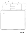
- the figure 4 has an electrode 4 used in the second embodiment.
- the plate head 6 is attached to an edge of the plate 5.
- the electrode 4 has a tongue 6L formed in the plate head 6. The method of forming the tongue 6L will be explained in more detail later.
- the figure 5 illustrates a stack of electrodes according to a second embodiment of the invention.
- the tabs 6L of the plate heads 6, described with reference to FIG. figure 4 form the portion 6a which is folded along an axis v perpendicular to the edges of the plates 5 to which the plate heads 6 are fixed.
- the figure 6 shows a set of electrodes according to the second embodiment associated with a current output terminal 8.
- the stack of plate heads 6 is soldered to the current output terminal 8 via the side opposite to said portion. 6a folded.
- the stack of the plate heads 6 has a first face on which a portion 6a is folded in a fold v perpendicular to the edges of the plates 5 to which the plate heads 6 are attached, and a second face, opposite to the first, which is soldered to the current output terminal 8.
- the soldering of a stack of plate heads 6 to its current output terminal 8 takes the form of a solder drop which includes at least a portion of the terminal 8 and all the plate heads 6 of the stack, folded portion 6a of the stack holding said drop of solder. Thus, all the electrodes are electrically connected to the current output terminal 8.
- the solder drop extends over substantially the entire thickness of the stack of plate heads 6 located under the folded portion 6a. Part of the thicknesses of the plate heads 6 constituting folded portion 6a may also be included in the solder drop. However, the folded portion 6a does not have primarily an electrical functionality, but a mechanical functionality that consists of confining the solder drop to prevent a leakage of material to the electrochemical bundle.
- the accumulator according to the invention has plate heads 6 whose welding with a current output terminal 8 has been obtained securely and efficiently, without bringing additional material, and without a dedicated machining of the output terminal of current 8.
- the electrode stacks presented in figures 2 and 3 , and in figures 5 and 6 are respectively mounted in known manner within an electrochemical bundle.
- the figure 7 schematically illustrates an electrochemical bundle 3 of an accumulator according to the first embodiment of the invention placed in a container 2.
- the electrochemical bundle 3 consists of a stack of alternately positive and negative electrodes in the direction of the stack , the electrode plates 5, 5 'being isolated from each other by a separator, not shown.
- the electrodes form a stack such that the plate heads 6 of the positive polarity electrodes are superimposed on the one hand, and the plate heads 6 'of the negative polarity electrodes are superposed on the other hand; the two sets of plate heads facing one side of the beam 3.
- the positive plate heads 6 form a first stack of plate heads and the negative plate heads 6 'form a second stack of plate heads.
- the preceding descriptions of a plate head stack 6 and of the soldering of the plate head stack 6 to a current output terminal 8 are valid for each of the two stacks of plate heads 6, 6 'positive and negative respectively welded to a positive current output terminal 8 and a negative current output terminal 8 '.
- the accumulator may comprise two stacks of positive plate heads 6 welded on either side of the positive current output terminal 8.
- the accumulator may comprise two stacks of negative plate heads 6 'welded on either side of the negative current output terminal 8'.
- Such an embodiment can be implemented when the number of plate heads is important. The thickness of the stack of plate heads is then such that it becomes difficult, or even impossible, to make the fold, whether along an axis h parallel to or an axis v perpendicular to the edges of the plates 5. It is then possible to separate the stack of plate heads in two subgroup stack for the same polarity.
- Each of the stacks of plate heads 6, 6 'positive or negative has the characteristics described above.
- the positive or negative current output terminal 8, 8 ' will be positioned between two stacks of plate heads 6, 6', and welded to these two stacks of plate heads 6, 6 'via opposite sides to portions 6a, 6a 'folded.
- the invention also relates to a method of manufacturing an accumulator in which the operation of welding the plate heads 6, 6 'to a current output terminal 8, 8' is carried out without leakage of the molten material, and without additional piece or machining of the terminal.
- the method according to the invention comprises the steps of supplying an electrochemical bundle 3, folding a portion 6a, 6a 'of a stack of plate heads 6, 6', and assembling and welding the heads of plate 6, 6 'on the current output terminals 8, 8'.
- the plate heads 6, 6' undergo an operation of expansion and folding.
- a portion 6a, 6a 'of the stack of plate heads 6, 6' is folded back on itself.
- the portion 6a, 6a ' is folded over a face of said stack of plate heads 6, 6'. It may be difficult to directly bend the portion 6a, 6a 'due to the cumulative thickness of the plate heads 6, 6' in the stack of plate heads 6, 6 '.
- This folding operation can then be assisted by an axis or cylindrical piece positioned at the base of the portion 6a, 6a '.
- the portion 6a, 6a ' is folded along an axis h parallel to the edges of the plates 5.
- the portion 6a, 6a ' is folded along an axis v perpendicular to the edges of the plates 5.
- the figure 4 illustrates an electrode 4 used for the method according to the second embodiment.
- the electrode 4 has a tongue 6L which is defined by a cut-out in the plate head 6 in a direction parallel to the edge of the plate 5 to which the plate head 6 is fixed. This cut is made in the strip which makes it possible to constitute the plate head 6, for example by stamping with a suitable punch.
- the plate heads 6 are expanded and the tabs 6L form a stack which constitutes the portion 6a which can be folded along an axis v perpendicular to the edges of the plates 5.
- the stack of plate heads 6, 6 ' is first positioned on the current output terminal 8, 8' of the polarity corresponding, with the portion 6a, 6a 'folded on the opposite side to the terminal.
- the welding can then be performed, for example in a resistance welder: a first welding electrode is positioned on the folded portion 6a, 6a of the stack of plate heads 6, 6 'and a second welding electrode is positioned either on the terminal 8, 8 'if a single stack of plate heads is soldered to the terminal, or on the portion 6a, 6a' folded of a second stack of plate heads 6, 6 'to be welded to the terminal 8, 8 '.
- Pressure and electrical current flow is applied between the welding electrodes causing the melting of the materials; there is then a risk of leakage of the molten material under the effect of the pressure exerted.
- the portion 6a, 6a 'folded will confine the weld, and prevent leakage of the molten material.
- Said folded portion 6a, 6a provides material to contain the weld. Thus, it is not necessary to bring additional material, nor to perform complex machining of the current output terminal 8, 8 '.
- the folded portion 6a, 6a confines the molten metal during welding, thereby eliminating any risk of burns or short-circuiting of the electrochemical bundle 3.
- the folded portion 6a, 6a of the stack of plate heads 6, 6 'thus performs a mechanical maintenance of the weld and has no electrical function.
- the accumulator according to the invention may be of the NiCd, NiMH or NiZn type, and the method according to the invention is particularly suitable for the manufacture of NiCd, NiMH or NiZn type accumulators.
Landscapes
- Chemical & Material Sciences (AREA)
- Chemical Kinetics & Catalysis (AREA)
- Electrochemistry (AREA)
- General Chemical & Material Sciences (AREA)
- Secondary Cells (AREA)
- Connection Of Batteries Or Terminals (AREA)
Claims (15)
- Akkumulator, welcher umfasst:- einen Behälter (2), der ein elektrochemisches Bündel (3) enthält, das aus einer Reihe abwechselnd angeordneter positiver Elektroden und negativer Elektroden besteht, die durch Separatoren getrennt sind, wobei jede Elektrode (4) eine Platte (5, 5') und einen Plattenkopf (6, 6') aufweist;- eine positive Stromausgangsklemme (8) und eine negative Stromausgangsklemme (8'),wobei ein Stapel von positiven Plattenköpfen (6) mindestens einen auf sich selbst zurückgebogenen Stapelabschnitt (6a) aufweist, wobei der Stapel von Plattenköpfen auf der diesem zurückgebogenen Abschnitt gegenüberliegenden Seite an die positive Stromausgangsklemme (8) angeschweißt ist,
und wobei ein Stapel von negativen Plattenköpfen (6') mindestens einen auf sich selbst zurückgebogenen Stapelabschnitt (6a') aufweist, wobei der Stapel von Plattenköpfen auf der diesem zurückgebogenen Abschnitt gegenüberliegenden Seite an die negative Stromausgangsklemme (8') angeschweißt ist. - Akkumulator nach Anspruch 1, welcher zwei Stapel von positiven Plattenköpfen (6) umfasst, die beiderseits der positiven Stromausgangsklemme (8) angeschweißt sind.
- Akkumulator nach Anspruch 1 oder 2, welcher zwei Stapel von negativen Plattenköpfen (6') umfasst, die beiderseits der negativen Stromausgangsklemme (8') angeschweißt sind.
- Akkumulator nach einem der Ansprüche 1 bis 3, wobei der Plattenkopf (6, 6') jeder Elektrode (4) an einem Rand der Platte (5, 5') der Elektrode (4) befestigt ist und das Umbiegen des Abschnitts (6, 6a') des Stapels entlang einer Achse (h) erfolgt, die zu den Rändern der Platten (5, 5'), an denen die Plattenköpfe (6, 6') befestigt sind, parallel ist.
- Akkumulator nach einem der Ansprüche 1 bis 3, wobei der Plattenkopf (6, 6') jeder Elektrode (4) an einem Rand der Platte (5, 5') der Elektrode (4) befestigt ist und das Umbiegen des Abschnitts (6, 6a') des Stapels entlang einer Achse (v) erfolgt, die zu den Rändern der Platten (5, 5'), an denen die Plattenköpfe (6, 6') befestigt sind, senkrecht ist.
- Akkumulator nach einem der vorhergehenden Ansprüche, wobei die Schweißverbindung eines Stapels von Plattenköpfen (6, 6') mit einer Klemme (8, 8') einen Schweißtropfen bildet, welcher mindestens einen Teil der Klemme (8, 8') und alle Plattenköpfe (6, 6') des Stapels einschließt, wobei der zurückgebogene Abschnitt (6a, 6a') des Stapels nicht vollständig in diesem Schweißtropfen eingeschlossen ist.
- Akkumulator nach einem der vorhergehenden Ansprüche vom Typ Nickel-Cadmium (NiCd), Nickel-Metallhydrid (NiMH) oder Nickel-Zink (NiZn).
- Verfahren zur Herstellung eines Akkumulators, welches die folgenden Schritte umfasst:- Bereitstellen eines elektrochemischen Bündels (3), das eine Reihe abwechselnd angeordneter positiver Elektroden und negativer Elektroden umfasst, die durch Separatoren getrennt sind, wobei jede Elektrode (4) eine Platte (5, 5') und einen Plattenkopf (6, 6') aufweist;- Zurückbiegen eines Abschnitts (6a) eines Stapels von positiven Plattenköpfen (6) auf sich selbst und Zurückbiegen eines Abschnitts (6a') eines Stapels von negativen Plattenköpfen (6') auf sich selbst;- Anschweißen jedes Stapels von Plattenköpfen (6, 6') an eine jeweilige Stromausgangsklemme (8, 8'), wobei sich der zurückgebogene Abschnitt (6a, 6a') auf der der Klemme (8, 8') gegenüberliegenden Seite befindet, durch Positionieren einer Schweißelektrode auf dem zurückgebogenen Abschnitt (6a, 6a').
- Verfahren zur Herstellung eines Akkumulators nach Anspruch 8, wobei der Plattenkopf (6, 6') jeder Elektrode (4) an einem Rand der Platte (5, 5') der Elektrode (4) befestigt wird und das Umbiegen des Abschnitts (6, 6a') entlang einer Achse (h) durchgeführt wird, die zu den Rändern der Platten (5, 5'), an denen die Plattenköpfe (6, 6') befestigt sind, parallel ist.
- Verfahren zur Herstellung eines Akkumulators nach Anspruch 8, welches außerdem einen Schritt umfasst, der darin besteht, jeden Plattenkopf (6, 6') derart zuzuschneiden, dass eine Zunge (6L, 6L') gebildet wird, die den zurückzubiegenden Abschnitt (6a, 6a') darstellt.
- Verfahren zur Herstellung eines Akkumulators nach Anspruch 10, wobei der Plattenkopf (6, 6') jeder Elektrode (4) an einem Rand der Platte (5, 5') der Elektrode (4) befestigt wird und das Umbiegen des Abschnitts (6, 6a') entlang einer Achse (v) durchgeführt wird, die zu den Rändern der Platten (5, 5'), an denen die Plattenköpfe (6, 6') befestigt sind, senkrecht ist.
- Verfahren zur Herstellung eines Akkumulators nach einem der Ansprüche 8 bis 11, wobei der Abschnitt (6a, 6a') eines Stapels von Plattenköpfen (6, 6') um eine Achse auf sich selbst zurückgebogen wird.
- Verfahren zur Herstellung eines Akkumulators nach einem der Ansprüche 8 bis 12, wobei jede Schweißung direkt an der Klemme (8, 8') ohne ein zusätzliches Teil durchgeführt wird.
- Verfahren zur Herstellung eines Akkumulators nach einem der Ansprüche 8 bis 13, wobei jede Schweißung direkt an einem Umfang der Klemme (8, 8') durchgeführt wird.
- Verfahren zur Herstellung eines Akkumulators nach einem der Ansprüche 8 bis 14, welches außerdem einen Schritt, der darin besteht, das elektrochemische Bündel (3) in einem Behälter (2) anzuordnen, und einen Schritt, der darin besteht, den Behälter mit Elektrolyt zu füllen, umfasst.
Applications Claiming Priority (1)
| Application Number | Priority Date | Filing Date | Title |
|---|---|---|---|
| FR0901693A FR2944150B1 (fr) | 2009-04-07 | 2009-04-07 | Accumulateur et procede de fabrication |
Publications (2)
| Publication Number | Publication Date |
|---|---|
| EP2239802A1 EP2239802A1 (de) | 2010-10-13 |
| EP2239802B1 true EP2239802B1 (de) | 2014-07-02 |
Family
ID=41353795
Family Applications (1)
| Application Number | Title | Priority Date | Filing Date |
|---|---|---|---|
| EP10157895.3A Ceased EP2239802B1 (de) | 2009-04-07 | 2010-03-26 | Batterie und Hestellungsverfahren |
Country Status (2)
| Country | Link |
|---|---|
| EP (1) | EP2239802B1 (de) |
| FR (1) | FR2944150B1 (de) |
Families Citing this family (3)
| Publication number | Priority date | Publication date | Assignee | Title |
|---|---|---|---|---|
| US20110206976A1 (en) * | 2010-02-19 | 2011-08-25 | Kyung-Mo Yoo | Electrode assembly and secondary battery using the same |
| JP2019033031A (ja) * | 2017-08-09 | 2019-02-28 | 日立化成株式会社 | 格子体及びその製造方法、並びに、鉛蓄電池及びその製造方法 |
| FR3110772B1 (fr) | 2020-05-20 | 2022-12-02 | Accumulateurs Fixes | Ensemble électrochimique, procédé et installation de fabrication correspondants |
Family Cites Families (6)
| Publication number | Priority date | Publication date | Assignee | Title |
|---|---|---|---|---|
| FR2468213A1 (fr) * | 1979-10-19 | 1981-04-30 | Accumulateurs Fixes | Accumulateur electrique a jonction par peigne resistant aux vibrations |
| FR2748606A1 (fr) | 1996-05-07 | 1997-11-14 | Accumulateurs Fixes | Procede et ensemble de connexion de plaques d'electrodes a une borne ou generateur electrochimique |
| FR2752090A1 (fr) | 1996-08-01 | 1998-02-06 | Accumulateurs Fixes | Generateur electrochimique a tetes de plaques d'electrodes ecartees par un cordon de matiere |
| CN1205687C (zh) * | 2000-12-27 | 2005-06-08 | 三菱化学株式会社 | 锂二次电池 |
| KR100483994B1 (ko) * | 2002-06-12 | 2005-04-18 | 주식회사 이글피쳐코캄 | 리튬 2차 전지용 크루드 셀의 전극탭 처리 방법 및 그에따른 크루드 셀 및 이를 채용한 리튬 2차 전지 |
| US7592097B2 (en) * | 2004-04-26 | 2009-09-22 | Greatbatch Ltd. | Electrochemical cell designs with anode plates and connections which facilitate heat dissipation |
-
2009
- 2009-04-07 FR FR0901693A patent/FR2944150B1/fr not_active Expired - Fee Related
-
2010
- 2010-03-26 EP EP10157895.3A patent/EP2239802B1/de not_active Ceased
Also Published As
| Publication number | Publication date |
|---|---|
| FR2944150B1 (fr) | 2011-05-06 |
| EP2239802A1 (de) | 2010-10-13 |
| FR2944150A1 (fr) | 2010-10-08 |
Similar Documents
| Publication | Publication Date | Title |
|---|---|---|
| JP4378657B2 (ja) | 電池および電源装置 | |
| JP5587061B2 (ja) | 抵抗溶接用通電ブロック、この通電ブロックを用いた密閉電池の製造方法及び密閉電池 | |
| EP2093820B1 (de) | Elektrische Verbindung für Stromakkumulator | |
| CN103155223B (zh) | 电池用负极端子 | |
| JP5558955B2 (ja) | 角形密閉二次電池 | |
| CN102124592A (zh) | 二次电池的制造方法及二次电池 | |
| JP2009110751A (ja) | 二次電池 | |
| WO2007004335A1 (ja) | 電池間接続装置 | |
| EP1898481A1 (de) | Vorrichtung mit elektrischem Anschluss für Ausgangsklemme eines Stromakkumulators | |
| US20150188116A1 (en) | Joint structure, joining method, secondary battery, and method of manufacturing secondary battery | |
| FR2913530A1 (fr) | Terminal electrique pour accumulateur etanche. | |
| KR20120007467A (ko) | 각형 밀폐 2차전지 및 그 제조방법 | |
| KR102309416B1 (ko) | 박판을 이용한 리드 단선을 개선하는 파우치형 이차전지 및 그 제조방법 | |
| EP3130020A1 (de) | Elektrochemischer lithium-ionen-akku mit direkt an die elektrodenanordnung angeschlossenem anschluss und zugehöriges herstellungsverfahren | |
| JP2007026945A (ja) | 電池とその製造方法 | |
| KR102157495B1 (ko) | 파우치형 배터리 셀 및 그 제조방법 | |
| FR3125172A1 (fr) | Pièce de connexion pour élément électrochimique de format prismatique | |
| EP3035411B1 (de) | Verbindungsverfahren in einem akkumulator, und so verbundener akkumulator | |
| EP2239802A1 (de) | Batterie und Hestellungsverfahren | |
| JP2018125068A (ja) | 二次電池の製造方法 | |
| FR3052917A1 (fr) | Electrode pour faisceau electrochimique d'un accumulateur metal-ion ou d'un supercondensateur, procede de realisation du faisceau et de l'accumulateur associes | |
| FR2824667A1 (fr) | Connectique interne pour generateur electrochimique de forte puissance | |
| JP5158435B2 (ja) | 電池及びその製造方法 | |
| EP3316350B1 (de) | Elektrisches anschlussstück für akkumulator | |
| CN103314469B (zh) | 电池 |
Legal Events
| Date | Code | Title | Description |
|---|---|---|---|
| PUAI | Public reference made under article 153(3) epc to a published international application that has entered the european phase |
Free format text: ORIGINAL CODE: 0009012 |
|
| AK | Designated contracting states |
Kind code of ref document: A1 Designated state(s): AT BE BG CH CY CZ DE DK EE ES FI FR GB GR HR HU IE IS IT LI LT LU LV MC MK MT NL NO PL PT RO SE SI SK SM TR |
|
| RBV | Designated contracting states (corrected) |
Designated state(s): DE FR GB |
|
| 17P | Request for examination filed |
Effective date: 20110413 |
|
| GRAP | Despatch of communication of intention to grant a patent |
Free format text: ORIGINAL CODE: EPIDOSNIGR1 |
|
| RIC1 | Information provided on ipc code assigned before grant |
Ipc: H01M 2/28 20060101ALI20131220BHEP Ipc: H01M 2/26 20060101AFI20131220BHEP |
|
| INTG | Intention to grant announced |
Effective date: 20140127 |
|
| RIN1 | Information on inventor provided before grant (corrected) |
Inventor name: SAINT-GERARD, ALAIN Inventor name: GILABERT, CLAUDE Inventor name: LANNE-TOUYAGUE, FRANCOIS |
|
| GRAS | Grant fee paid |
Free format text: ORIGINAL CODE: EPIDOSNIGR3 |
|
| GRAA | (expected) grant |
Free format text: ORIGINAL CODE: 0009210 |
|
| AK | Designated contracting states |
Kind code of ref document: B1 Designated state(s): DE FR GB |
|
| REG | Reference to a national code |
Ref country code: GB Ref legal event code: FG4D Free format text: NOT ENGLISH |
|
| REG | Reference to a national code |
Ref country code: DE Ref legal event code: R096 Ref document number: 602010017152 Country of ref document: DE Effective date: 20140814 |
|
| REG | Reference to a national code |
Ref country code: DE Ref legal event code: R097 Ref document number: 602010017152 Country of ref document: DE |
|
| PLBE | No opposition filed within time limit |
Free format text: ORIGINAL CODE: 0009261 |
|
| STAA | Information on the status of an ep patent application or granted ep patent |
Free format text: STATUS: NO OPPOSITION FILED WITHIN TIME LIMIT |
|
| 26N | No opposition filed |
Effective date: 20150407 |
|
| REG | Reference to a national code |
Ref country code: FR Ref legal event code: PLFP Year of fee payment: 7 |
|
| REG | Reference to a national code |
Ref country code: FR Ref legal event code: PLFP Year of fee payment: 8 |
|
| REG | Reference to a national code |
Ref country code: FR Ref legal event code: PLFP Year of fee payment: 9 |
|
| REG | Reference to a national code |
Ref country code: DE Ref legal event code: R079 Ref document number: 602010017152 Country of ref document: DE Free format text: PREVIOUS MAIN CLASS: H01M0002260000 Ipc: H01M0050531000 |
|
| PGFP | Annual fee paid to national office [announced via postgrant information from national office to epo] |
Ref country code: DE Payment date: 20220330 Year of fee payment: 13 |
|
| PGFP | Annual fee paid to national office [announced via postgrant information from national office to epo] |
Ref country code: GB Payment date: 20220406 Year of fee payment: 13 |
|
| PGFP | Annual fee paid to national office [announced via postgrant information from national office to epo] |
Ref country code: FR Payment date: 20230321 Year of fee payment: 14 |
|
| REG | Reference to a national code |
Ref country code: DE Ref legal event code: R119 Ref document number: 602010017152 Country of ref document: DE |
|
| GBPC | Gb: european patent ceased through non-payment of renewal fee |
Effective date: 20230326 |
|
| PG25 | Lapsed in a contracting state [announced via postgrant information from national office to epo] |
Ref country code: GB Free format text: LAPSE BECAUSE OF NON-PAYMENT OF DUE FEES Effective date: 20230326 |
|
| PG25 | Lapsed in a contracting state [announced via postgrant information from national office to epo] |
Ref country code: GB Free format text: LAPSE BECAUSE OF NON-PAYMENT OF DUE FEES Effective date: 20230326 Ref country code: DE Free format text: LAPSE BECAUSE OF NON-PAYMENT OF DUE FEES Effective date: 20231003 |
|
| PG25 | Lapsed in a contracting state [announced via postgrant information from national office to epo] |
Ref country code: FR Free format text: LAPSE BECAUSE OF NON-PAYMENT OF DUE FEES Effective date: 20240331 |
|
| PG25 | Lapsed in a contracting state [announced via postgrant information from national office to epo] |
Ref country code: FR Free format text: LAPSE BECAUSE OF NON-PAYMENT OF DUE FEES Effective date: 20240331 |