EP2239992A2 - Dispositif de communication sans fil, système, procédé et programme - Google Patents
Dispositif de communication sans fil, système, procédé et programme Download PDFInfo
- Publication number
- EP2239992A2 EP2239992A2 EP20100250203 EP10250203A EP2239992A2 EP 2239992 A2 EP2239992 A2 EP 2239992A2 EP 20100250203 EP20100250203 EP 20100250203 EP 10250203 A EP10250203 A EP 10250203A EP 2239992 A2 EP2239992 A2 EP 2239992A2
- Authority
- EP
- European Patent Office
- Prior art keywords
- wireless communication
- function
- function information
- communication device
- station
- Prior art date
- Legal status (The legal status is an assumption and is not a legal conclusion. Google has not performed a legal analysis and makes no representation as to the accuracy of the status listed.)
- Withdrawn
Links
Images


Classifications
-
- H—ELECTRICITY
- H04—ELECTRIC COMMUNICATION TECHNIQUE
- H04W—WIRELESS COMMUNICATION NETWORKS
- H04W8/00—Network data management
- H04W8/005—Discovery of network devices, e.g. terminals
-
- H—ELECTRICITY
- H04—ELECTRIC COMMUNICATION TECHNIQUE
- H04W—WIRELESS COMMUNICATION NETWORKS
- H04W84/00—Network topologies
- H04W84/18—Self-organising networks, e.g. ad-hoc networks or sensor networks
- H04W84/20—Leader-follower arrangements
-
- H—ELECTRICITY
- H04—ELECTRIC COMMUNICATION TECHNIQUE
- H04W—WIRELESS COMMUNICATION NETWORKS
- H04W40/00—Communication routing or communication path finding
- H04W40/24—Connectivity information management, e.g. connectivity discovery or connectivity update
- H04W40/244—Connectivity information management, e.g. connectivity discovery or connectivity update using a network of reference devices, e.g. beaconing
-
- H—ELECTRICITY
- H04—ELECTRIC COMMUNICATION TECHNIQUE
- H04W—WIRELESS COMMUNICATION NETWORKS
- H04W76/00—Connection management
- H04W76/10—Connection setup
- H04W76/14—Direct-mode setup
-
- H—ELECTRICITY
- H04—ELECTRIC COMMUNICATION TECHNIQUE
- H04W—WIRELESS COMMUNICATION NETWORKS
- H04W84/00—Network topologies
- H04W84/02—Hierarchically pre-organised networks, e.g. paging networks, cellular networks, WLAN [Wireless Local Area Network] or WLL [Wireless Local Loop]
- H04W84/10—Small scale networks; Flat hierarchical networks
- H04W84/12—WLAN [Wireless Local Area Networks]
-
- H—ELECTRICITY
- H04—ELECTRIC COMMUNICATION TECHNIQUE
- H04W—WIRELESS COMMUNICATION NETWORKS
- H04W88/00—Devices specially adapted for wireless communication networks, e.g. terminals, base stations or access point devices
- H04W88/02—Terminal devices
- H04W88/06—Terminal devices adapted for operation in multiple networks or having at least two operational modes, e.g. multi-mode terminals
Definitions
- the present invention relates to a wireless communication device, a wireless communication system, a wireless communication method, and a program.
- an access point In the infrastructure mode of IEEE 802.11, the operation of an access point (AP) is started first, and notification information (beacon) is periodically transmitted from the access point at a frequency that is set in advance.
- a station finds the access point, which is a communication counterpart, by receiving the beacon transmitted from the access point.
- a method is assumed of determining an access point and a station by negotiation after connection has been completed, without distinguishing in advance an access point and a station among communicating devices. According to this method, since it is not known at what frequency the counterpart is operating, notifications, such as beacons, are transmitted while switching the frequencies, and when the frequencies of devices match at a certain timing, the notification information can be received for the first time and connection can be completed.
- a wireless communication device a wireless communication system, a wireless communication method, and a program which are novel and improved, and which enable to determine for sure which device will play the role of an access point by negotiation at the time of connection.
- a wireless communication device which includes a function information transmitting unit for transmitting, via a wireless communication network, function information relating to a function of the wireless communication device, a function information receiving unit for receiving function information transmitted from another device, a function information comparison unit for comparing the function information of the wireless communication device and the function information received from such other device, and a function determination unit for determining which of the wireless communication device and such other device is to play a function of an access point, based on a result of the comparison by the function information comparison unit.
- the function information transmitting unit may transmit, as the function information relating to the function of the wireless communication device, a weight for the function of the wireless communication device.
- the function information receiving unit may receive, as the function information transmitted from such other device, a weight for the function of such other device.
- the function information comparison unit may compare the respective weights for the wireless communication device and such other device.
- the function information transmitting unit may transmit, as the function information relating to the function of the wireless communication device, accumulated value of the weight of each function of the wireless communication device.
- the function information receiving unit may receive, as the function information transmitted from such other device, accumulated value of the weight of each function of such other device.
- the function information comparison unit may compare the respective accumulated values of the weights for the wireless communication device and such other device.
- a storage unit for storing priority relating to the function information may be included.
- the function information comparison unit may compare pieces of the function information based on the priority.
- the function information may be information relating to at least one of connection/non-connection of AC power, a remaining battery amount, a maximum communication speed, a number of usable frequency channels, presence or absence of a bridge function, a supported encoding method, a CPU processing capacity, presence or absence of a display, and a function of an input device.
- the function information may change flexibly depending on a current state of the wireless communication device or such other device.
- a weight calculation unit for calculating the weight for each function of such other device based on the function information transmitted from such other device may be included.
- the function information comparison unit may compare the weight for each function of the wireless communication device and the weight for each function of such other device.
- a wireless communication system which includes a first wireless communication device including a function information transmitting unit for transmitting to a second wireless communication device, via a wireless communication network, function information relating to a function of the first wireless communication device, a function information receiving unit for receiving function information transmitted from the second wireless communication device, a function information comparison unit for comparing the function information of the first wireless communication device and the function information received from the second wireless communication device, and a function determination unit for determining which of the first wireless communication device and the second wireless communication device is to play a function of an access point, based on a result of the comparison by the function information comparison unit, and the second wireless communication device including a function information transmitting unit for transmitting to the first wireless communication device, via the wireless communication network, the function information relating to the function of the second wireless communication device, a function information receiving unit for receiving the function information transmitted from the first wireless communication device, a function information comparison unit for comparing the function information of the second wireless communication device and the function information received from the first wireless communication
- a wireless communication method which includes the steps of transmitting, via a wireless communication network, function information relating to a function of a wireless communication device, receiving function information transmitted from another device; comparing the function information of the wireless communication device and the function information received from such other device, and determining which of the wireless communication device and such other device is to play a function of an access point, based on a result of the comparison.
- wireless LAN connection modes defined by IEEE 802.11, which is a wireless LAN standard, are an infrastructure mode of performing communication via an access point.
- a radio has to somehow find a connection counterpart. To find here means to be in a state where synchronization of frequency channels and timings can be established.
- the operation of an access point is started first, and a beacon is periodically transmitted at a frequency (referred to as F1) that is set in advance.
- the beacon is notification information including an ESS-ID, which is an identifier of a network, or the like.
- a station (STA) finds the access point, which is a communication counterpart, by receiving the beacon transmitted from the access point.
- the frequency of the station (STA) may be set by a user to be the same as the frequency F1 of the access point (AP), or the station may continue reception while switching the frequency channels defined by IEEE 802.11 one by one until the station detects the beacon.
- which device is an access point and which device is a station are determined at the time of manufacturing the devices, and a user selects an access point or a station at the time of purchase.
- the user sets a device to be an access point or a station after purchasing a device.
- a method can be assumed according to which two terminals are connected one-to-one in a simple manner by using the mechanism of IEEE 802.11 wireless LAN without the user consciously distinguishing between an access point and a station.
- the terminals are equal to each other without the distinction of access point and station, and at the time of communication, both start searching for each other at the same time.
- Negotiation is performed after each other is found, and one plays the role of a simple access point, and the other plays the role of a station. Accordingly, this method enables to realize a simple infrastructure mode without distinguishing between an access point and a station.
- the user specifies only the devices for performing communication without specifying in advance which device is to be the access point or the station, and the devices perform negotiation and one of the devices autonomously takes the role of the access point.
- a rule becomes necessary for determining at the time of negotiation which device is to be the access point.
- which terminal is to be the access point is autonomously determined by the devices, and an evaluation method and evaluation items for the autonomous determination are decided.
- which device is to take the role of the access point is determined, at the time of negotiation, based on the function information of each terminal (weights of functions, or the like) and the order of priority thereof.
- the present embodiment will be described in detail.
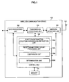
- FIG 1 is a block diagram showing an example of the configuration of a wireless communication device 100 according to each embodiment of the present invention.
- the wireless communication device 100 is configured to be able to communicate with other wireless communication device by a wireless communication network such as IEEE 802.11a, IEEE 802.11b and IEEE 802.11n, which are wireless LAN standards.
- a wireless communication network such as IEEE 802.11a, IEEE 802.11b and IEEE 802.11n, which are wireless LAN standards.
- each wireless communication device 100 includes a data processing unit 102, a transmission processing unit 104, a wireless interface unit 106, a control unit 108, a memory 110, and an antenna 112.
- the data processing unit 102 creates various data frames and data packets in response to a request from an upper layer, for example, and supplies the same to the transmission processing unit 104.
- the transmission processing unit 104 performs, at the time of transmission, processing such as adding to a packet generated at the data processing unit 102 various data heads or an error detection code such as a frame check sequence (FCS), and provides the data which has been processed to the wireless interface unit 106.
- the wireless interface unit 106 generates, from the data received from the transmission processing unit 104, a modulation signal in a frequency band of a carrier, and makes the same transmitted from the antenna 112 as a radio signal.
- the wireless interface unit 106 decodes the various data frames by down-converting the radio signal received by the antenna 112 and changing the same to a bit sequence. That is, the wireless interface unit 106 can function, in cooperation with the antenna 112, as a transmitting unit and a receiving unit.
- the transmission processing unit 104 analyzes the headers added to the various data frames supplied from the wireless interface unit 106 and checks, based on the error detection code, that each data frame includes no error, and then, supplies the various data frames to the data processing unit 102.
- the data processing unit 102 processes and analyzes the various data frames and data packets supplied from the transmission processing unit 104.
- the control unit 108 is a block for controlling the respective operations of the data processing unit 102, the transmission processing unit 104, and the wireless interface unit 106, and the control unit 108 can perform operations such as determination of a transmission/reception frequency, creation of a control message (notification information such as a beacon, a beacon acknowledgement, a probe request and a probe response), issuance of a transmission command for the control message, and interpretation of the control message, and the control unit 108 controls various operations of the wireless communication device 100, such as reception operation and transmission operation. Furthermore, the control unit 108 creates a control message including function information such as weight information of the present embodiment, and interprets the control message, for example.
- the control unit 108 includes, as main structural elements, a function-information creation/transmission-instruction unit 108a, a reception/interpretation processing unit 108b, a comparison unit 108c, and a determination unit 108d.
- the function-information creation/transmission-instruction unit 108a creates the control message including function information such as weight, or issues a transmission command for the control message.
- the reception/interpretation processing unit 108b performs a reception process or an interpretation process for the control message including the function information transmitted from the communication counterpart.
- the comparison unit 108c compares the function information of the self device (the device to which the unit in question belongs) and the function information transmitted from the communication counterpart.
- the determination unit 108d performs an operation of determining, based on the comparison result by the comparison unit 108c, which of the self device and the communication counterpart is to take the role of the access point or of the station.
- the memory 110 plays the role of a work area for the data processing by the control unit 108, and has a function of a storage medium for holding various types of data.
- Various storage media for example, a volatile memory such as a DRAM, a non-volatile memory such as an EEPROM, a hard disk and an optical disk, may be used as the memory 110.
- each block shown in FIG 1 can be configured from hardware (circuit).
- each block can be configured from a processor (CPU) and software (program) for making the processor function.
- the program can be stored in the storage medium included in the wireless communication device 100, such as the memory 110.
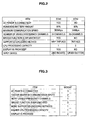
- FIG 2 is a schematic diagram showing the functions of the station 1 (STA1) and the station 2 (STA2).
- the station 1 and the station 2 have a specific function in relation to each of the items "AC power is connected?,” “remaining battery amount,” “maximum communication speed,” “number of usable frequency channels,” “bridge function is implemented?,” “supported encoding method,” “CPU processing capacity,” “display is provided?,” and “input device.”
- the station 1 and the station 2 differ from each other in function for each item. In the present embodiment, weights are set depending on these functions.
- FIG 3 is a schematic diagram showing examples of the weight to be given to each function shown in FIG 2 .
- the weight in case AC power is connected, the weight is "3.” In case the maximum communication speed is faster, the weight is "2.” In case the number of usable frequency channels is larger, the weight is “1.” In case a bridge function is implemented, the weight is “3.” In case the number of supported encoding methods is larger, the weight is “1.” In case the processing capacity of the CPU is higher, the weight is "1.” Also, in case a display is provided, the weight is "2.” In the present embodiment, the higher the weight, the more suited as an access point it is determined to be, and thus it tends to become the access point at the time of negotiation.
- the method of quantifying the CPU processing capacity is not particularly limited.
- the weight given to a device can be set to "1" in case the manufacturer (maker) of the device decides that the device has sufficient CPU processing capacity for operating as an access point. Also, in case the manufacturer of a device decides that the device does not have sufficient CPU processing capacity for operating as an access point, the weight given to the device can be set to "0.”
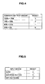
- FIG 4 is a schematic diagram showing weight changing depending on the remaining battery amount.
- the weight is set depending on the remaining amount. As shown in FIG 4 , when the remaining battery amount is 100% to 75%, the weight is 3; and when it is 74% to 50%, the weight is 2. Also, when the remaining battery amount is 49% to 25%, the weight is 1; and when it is 24% to 0%, the weight is 0.
- FIG 5 is a schematic diagram showing weight changing depending on the ability of an input device (user interface).
- the weight is set for the ability of an input device depending on the ability, and a device having a higher performing user interface is made to be the access point.
- the weight when an input device is not included, the weight is 0; when a push button is included as the input device, the weight is 1; and when a keyboard is included as the input device; the weight is 2.
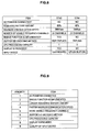
- FIG 6 is a schematic diagram showing the result of calculating, the weights for each of the station 1 and the station 2 shown in FIG 2 , based on FIGS. 3 to 5 .
- the weights are determined in accordance with FIGS. 3 to 5 for the functions of the station 1 and the station 2 shown in FIG. 2 , the result shown in FIG 6 is obtained where the weight of the station 1 (Weight(STA1)) is "15" and the weight of the station 2 (Weight(STA2)) is "4.”
- FIG 7 is a sequence diagram showing the flow of determining, in case the station 1 (STA1) and the station 2 (STA2) shown in FIG 2 start communication, which device is to operate as the access point.
- step S10 calculation of the weight information is performed at each of the station 1 and the station 2.
- step S10 the station 1 calculates the weight (Weight(STA1)) of itself; and in step S20, the station 2 calculates the weight (Weight(STA2)) of itself.
- each device transmits the accumulated value of the weights, it is also possible to obtain and transmit a weight only of a specific function.
- the information to be transmitted to another station does not have to be the weight, and may be the information itself on the functions as shown in FIG 2 , for example. In that case, calculation of the weight of a station, which is the communication counterpart, is performed by a station which has received the function information. The calculation of the weight can be performed at the function-information creation/transmission-instruction unit 108a, and the function-information creation/transmission-instruction 108a functions as a weight calculation unit.
- the station 2 compares, in step S24, the weight Weight(STA2) of itself and the weight Weight(STA1) received from the station 1, and decides whether Weight(STA2) is larger than Weight(STA1). In the example shown in FIG 7 , since Weight(STA2) is equal to or smaller than Weight(STA1) and the weight of the station 2 is smaller than the weight of the station 1, the process proceeds to step S26 and the station 2 is determined to be a station in the infrastructure mode.
- the station 1 will function as an access point after step S16, and thus it will transmit a beacon.
- the station 2 will function as a station in the infrastructure mode after step S26, and thus it will receive the beacon transmitted from the station 1 and will transmit data to the station 1.
- the station 2 will be an access point in step S16. Also, the station 1 will be a station in the infrastructure mode in step S26. In this case, after step S26, the station 2 will transmit a beacon and the station 1 will transmit data to the station 2.
- which device is to be an access point is determined by negotiation using the weights. Accordingly, a device showing higher suitability for an access point can be determined to be the access point, based on the functions of each device.
- which of the devices performing one-to-one communication will be an access point can be determined by setting a weight in accordance with the functions of each station.
- the second embodiment is for determining whether a device is to be an access point or a station, according to the priorities assigned to the functions of each station.
- FIG 8 is a schematic diagram showing the functions of the station 3 and the station 4.
- FIG 9 is a schematic diagram showing the order of priorities for becoming an access point, decided based on the functions shown in FIG 8 .
- the information shown in FIG 9 is acquired in advance by each station as shared information, and is stored in the memory 110, for example.
- the functions of the station 3 and the station 4 are determined in order starting from 1 of the priorities shown in FIG. 9 , according to each item. Which device is to be an access point is determined based on the superiority or inferiority per item.
- FIG 10 is a sequence diagram showing a flow of determining, according to the priorities, which of the station 3 and the station 4 is to be an access point.
- step S30 the station 3 transmits function information relating to priority 1 to the station 4.
- the function information relating to priority 1 is connection/non-connection of AC power, and as shown in FIG 8 , the station 3 does not have AC power (AC power is not connected).
- the station 3 transmits to the station 4 information that it does not have AC power.
- step S40 the station 4 transmits the function information relating to priority 1 to the station 3.
- the station 4 does not have AC power either.
- the station 4 transmits to the station 3 information that it does not have AC power.
- step S32 it is decided at the station 3 in step S32 that the station 3 does not have the function of priority 1 and that the station 4 also does not have the function of priority 1.
- which device is to be an access point is not determined based on the function of priority 1. Accordingly, the process proceeds to step S34 in this case.
- step S42 it is determined at the station 4 in step S42 that the station 3 does not have the function of priority 1 and that the station 4 also does not have the function of priority 1. In this case, which device is to be an access point is not determined based on the function of priority 1, and thus, the process proceeds to step S44.
- step 34 since which device to be an access point was not determined by the function of priority 1, the station 3 transmits to the station 4 function information relating to priority 2.
- the function information relating to priority 2 is presence or absence of a bridge function, and as shown in FIG 8 , the station 3 has the bridge function. Accordingly, in step S34, the station 3 transmits to the station 4 information that it has the bridge function.
- step S44 the station 4 transmits to the station 3 the function information relating to priority 2.
- the station 4 does not have the bridge function, and thus, the station 4 transmits to the station 3 in step S44 information that it does not have the bridge function.
- step S36 it is decided at the station 3 in step S36 that the station 3 has the function of priority 2 and the station 4 does not have the function of priority 2.
- which device is to be an access point can be determined based on the function of priority 2. Accordingly, the station 3 is determined in step S38 to be an access point.
- the station 4 is determined in step S48 to be a station in the infrastructure mode.
- the station 3 will function as an access point after step S38, and thus, it will transmit a beacon.
- the station 4 will function as a station in the infrastructure mode after step S48, and thus, it will receive the beacon transmitted from the station 3 and will transmit data to the station 3.
- FIG 10 an example is shown in which an item is transmitted one by one from the parameters of functions of higher priority and comparison is made at the stations 3 and 4.
- the station 3 and the station 4 may transmit to each other all the information shown in FIG 8 at one time, and comparison may be made in order starting from an item of high priority.
- a device showing higher suitability for an access point can be determined to be the access point by performing negotiation according to the priority of the functions of each station.
- FIGS. 11A to 11C are schematic diagrams for describing the bridge function.
- a terminal 1 is a terminal which has the bridge function.
- the terminal 1 is connected at the same time to both a terminal 2 and an access point.
- the terminal 2 and the access point can transmit/receive information by the bridge function of the terminal 1.
- a terminal 3 is a terminal which has the bridge function.
- the terminal 3 is connected at the same time to both a terminal 4 and a public wireless base station.
- the terminal 4 and the public wireless base station can transmit/receive information by the bridge function of the terminal 3.
- a terminal 5 is a terminal which has the bridge function.
- the terminal 5 is connected at the same time to both a terminal 6 and a terminal 7.
- the terminal 6 and the terminal 7 can transmit/receive information by the bridge function of the terminal 5.
- the bridge function is a function capable of relaying between two terminals at the time of the two terminals transmitting/receiving information.
- FIG 12 is a schematic diagram showing the configuration of an information processing apparatus 200 equipped with the wireless communication device 100.
- the information processing apparatus 200 is, for example, a device such as a personal computer
- the wireless communication device 100 is, for example, a device such as a wireless LAN card mounted within the personal computer.
- the configuration of the wireless communication device 100 is the same as that described with FIG 1 .
- the wireless communication device 100 is provided within the information processing apparatus 200.
- the information processing apparatus 200 includes an input device 202 such as a keyboard, an output device 204 such as a display, a control unit 206 such as a CPU, a power processing unit 208, a battery 210, and an external power interface 212.
- a signal from the input device 202 is input to the control unit 206.
- the input device 202, the output device 204, and the power processing unit 208 are controlled by the control unit 206.
- information such as "connection/non-connection of AC power,” “remaining battery amount,” “CPU processing capacity,” “display provision,” and “capacity of input device” described with FIG 2 is information relating also to the information processing apparatus 200. Accordingly, the control unit 108 of the wireless communication device 100 can perceive these pieces of information relating to the information processing apparatus 200 by the control unit 206 of the information processing apparatus 200 transmitting the information to the control unit 108 of the wireless communication device 100. Also, regarding the CPU processing capacity, since the control unit 206 of the information processing apparatus 200 and the control unit 108 of the wireless communication device 100 have to perform processing in cooperation, the total of the processing capacities of the control units 108 and 206 of both sides can be taken as the "CPU processing capacity" of FIG 2 .
Landscapes
- Engineering & Computer Science (AREA)
- Computer Networks & Wireless Communication (AREA)
- Signal Processing (AREA)
- Databases & Information Systems (AREA)
- Mobile Radio Communication Systems (AREA)
Priority Applications (2)
| Application Number | Priority Date | Filing Date | Title |
|---|---|---|---|
| EP15158470.3A EP2908598B1 (fr) | 2009-04-06 | 2010-02-08 | Dispositif de communication sans fil, système, procédé et programme |
| EP17162644.3A EP3209090B1 (fr) | 2009-04-06 | 2010-02-08 | Dispositif de communication sans fil, système, procédé et programme |
Applications Claiming Priority (1)
| Application Number | Priority Date | Filing Date | Title |
|---|---|---|---|
| JP2009092402A JP5705415B2 (ja) | 2009-04-06 | 2009-04-06 | 無線通信装置、通信システム、通信方法及びプログラム |
Related Child Applications (2)
| Application Number | Title | Priority Date | Filing Date |
|---|---|---|---|
| EP17162644.3A Division EP3209090B1 (fr) | 2009-04-06 | 2010-02-08 | Dispositif de communication sans fil, système, procédé et programme |
| EP15158470.3A Division EP2908598B1 (fr) | 2009-04-06 | 2010-02-08 | Dispositif de communication sans fil, système, procédé et programme |
Publications (2)
| Publication Number | Publication Date |
|---|---|
| EP2239992A2 true EP2239992A2 (fr) | 2010-10-13 |
| EP2239992A3 EP2239992A3 (fr) | 2014-04-16 |
Family
ID=42338362
Family Applications (3)
| Application Number | Title | Priority Date | Filing Date |
|---|---|---|---|
| EP15158470.3A Active EP2908598B1 (fr) | 2009-04-06 | 2010-02-08 | Dispositif de communication sans fil, système, procédé et programme |
| EP20100250203 Withdrawn EP2239992A3 (fr) | 2009-04-06 | 2010-02-08 | Dispositif de communication sans fil, système, procédé et programme |
| EP17162644.3A Active EP3209090B1 (fr) | 2009-04-06 | 2010-02-08 | Dispositif de communication sans fil, système, procédé et programme |
Family Applications Before (1)
| Application Number | Title | Priority Date | Filing Date |
|---|---|---|---|
| EP15158470.3A Active EP2908598B1 (fr) | 2009-04-06 | 2010-02-08 | Dispositif de communication sans fil, système, procédé et programme |
Family Applications After (1)
| Application Number | Title | Priority Date | Filing Date |
|---|---|---|---|
| EP17162644.3A Active EP3209090B1 (fr) | 2009-04-06 | 2010-02-08 | Dispositif de communication sans fil, système, procédé et programme |
Country Status (4)
| Country | Link |
|---|---|
| US (6) | US8934464B2 (fr) |
| EP (3) | EP2908598B1 (fr) |
| JP (1) | JP5705415B2 (fr) |
| CN (2) | CN105916217B (fr) |
Cited By (4)
| Publication number | Priority date | Publication date | Assignee | Title |
|---|---|---|---|---|
| EP2448366A3 (fr) * | 2010-11-02 | 2014-12-31 | LG Electronics Inc. | Procédé pour déterminer un propriétaire de groupe dans un réseau sans fil |
| EP2704515A4 (fr) * | 2011-07-25 | 2015-01-07 | Panasonic Corp | Dispositif de communication, procédé de communication et programme de communication |
| WO2015067420A1 (fr) * | 2013-11-06 | 2015-05-14 | Sony Corporation | Politiques d'acheminement de trafic basées sur les sessions |
| EP3352527A1 (fr) * | 2017-01-24 | 2018-07-25 | ABB Schweiz AG | Réseau de communication sans fil |
Families Citing this family (17)
| Publication number | Priority date | Publication date | Assignee | Title |
|---|---|---|---|---|
| JP5705415B2 (ja) | 2009-04-06 | 2015-04-22 | ソニー株式会社 | 無線通信装置、通信システム、通信方法及びプログラム |
| JP2012182742A (ja) * | 2011-03-02 | 2012-09-20 | Ricoh Co Ltd | 無線通信装置、電子装置、簡易アクセスポイントの決定方法及び更新方法 |
| JP5664390B2 (ja) * | 2011-03-23 | 2015-02-04 | ソニー株式会社 | 無線通信装置、無線通信方法、プログラム、および無線通信システム |
| KR101267983B1 (ko) * | 2011-04-21 | 2013-05-27 | 아이테크 도쿄 코포레이션 | 무선랜 기반 피어투피어 응용간 연결 방법, 무선랜 기반 피어투피어 응용간 연결성 유지 방법 및 무선랜 기반 피어 단말 |
| US20140201280A1 (en) * | 2012-04-23 | 2014-07-17 | Emily Qi | Systems and methods for resuming group owner responsibilities for peer-to-peer wireless connections |
| EP2814299B1 (fr) * | 2013-06-13 | 2020-09-16 | Fraunhofer-Gesellschaft zur Förderung der angewandten Forschung e.V. | Procédé d'organisation d'un réseau sans fil |
| JP6347633B2 (ja) * | 2013-06-14 | 2018-06-27 | キヤノン株式会社 | 通信装置、通信方法およびプログラム |
| US20150095679A1 (en) * | 2013-09-30 | 2015-04-02 | Sonos, Inc. | Transitioning A Networked Playback Device Between Operating Modes |
| US10779838B1 (en) | 2013-11-13 | 2020-09-22 | Joseph W Blake, III | Instrument for serially applying clips to a surgical site |
| JP2015154143A (ja) * | 2014-02-12 | 2015-08-24 | ソニー株式会社 | 情報処理装置および情報処理方法 |
| WO2015190038A1 (fr) * | 2014-06-10 | 2015-12-17 | パナソニックIpマネジメント株式会社 | Procédé d'authentification, système d'authentification, et contrôleur |
| JP6751894B2 (ja) * | 2014-06-10 | 2020-09-09 | パナソニックIpマネジメント株式会社 | 認証方法およびコントローラ |
| US10098641B1 (en) | 2014-08-21 | 2018-10-16 | Joseph W Blake, III | Jaws and cams for clip applying instruments |
| US9968363B2 (en) | 2014-10-20 | 2018-05-15 | Joseph W. Blake, III | Multi-clip applier |
| JPWO2016167121A1 (ja) * | 2015-04-15 | 2017-09-14 | 三菱電機株式会社 | 無線通信システム、親機、子機及び無線接続方法 |
| JP2016028354A (ja) * | 2015-11-05 | 2016-02-25 | ソニー株式会社 | 情報処理装置、情報処理方法およびコンピュータプログラム |
| JP6475207B2 (ja) * | 2016-09-13 | 2019-02-27 | Necプラットフォームズ株式会社 | 無線通信装置、方法およびプログラム |
Citations (5)
| Publication number | Priority date | Publication date | Assignee | Title |
|---|---|---|---|---|
| EP1718028A1 (fr) * | 2005-04-27 | 2006-11-02 | Canon Kabushiki Kaisha | Appareil et procédé de configuration de paramètres de configuration |
| JP2007074561A (ja) | 2005-09-08 | 2007-03-22 | Advanced Telecommunication Research Institute International | 無線ネットワークのルーティング方法及び無線通信システム |
| JP2008523697A (ja) | 2004-12-10 | 2008-07-03 | サムスン エレクトロニクス カンパニー リミテッド | 競争に基づく分散型macを用いた無線ネットワークにおけるトラフィックの受信可否の通知方法及びアクティブ又は非アクティブ状態の決定方法 |
| JP2008283590A (ja) | 2007-05-14 | 2008-11-20 | Sony Corp | 無線通信端末、通信方法および無線通信システム |
| JP2009092402A (ja) | 2007-10-04 | 2009-04-30 | Toda Constr Co Ltd | 地震情報による建物の震度予測システム |
Family Cites Families (24)
| Publication number | Priority date | Publication date | Assignee | Title |
|---|---|---|---|---|
| JPH11146030A (ja) * | 1997-11-07 | 1999-05-28 | Nec Corp | 無線会議システムの仮親決定方式 |
| JP2001103570A (ja) * | 1999-09-30 | 2001-04-13 | Toshiba Corp | 通信システム、この通信システムに用いられる通信装置及び通信方法 |
| GB0004919D0 (en) * | 2000-03-02 | 2000-04-19 | Koninkl Philips Electronics Nv | Ad-hoc radio communication system |
| JP3848235B2 (ja) * | 2002-10-04 | 2006-11-22 | ソニー株式会社 | 通信処理装置、通信処理システム、および方法、並びにコンピュータ・プログラム |
| US7020438B2 (en) * | 2003-01-09 | 2006-03-28 | Nokia Corporation | Selection of access point in a wireless communication system |
| WO2004109996A1 (fr) * | 2003-06-02 | 2004-12-16 | Matsushita Electric Industrial Co., Ltd. | Dispositif, procede et programme permettant d'effectuer un processus de commutation maitre/esclave |
| US20050007979A1 (en) * | 2003-07-07 | 2005-01-13 | Intel Corporation | Uniform channel spreading in a wireless local area network using dynamic frequency selection |
| JP2005033285A (ja) * | 2003-07-08 | 2005-02-03 | Hitachi Ltd | 無線情報端末及び無線通信システム |
| US7463886B2 (en) * | 2003-09-16 | 2008-12-09 | Spyder Navigations L.L.C. | Method and system for supporting residual energy awareness in an ad hoc wireless communications network |
| WO2005034434A1 (fr) * | 2003-10-03 | 2005-04-14 | Sharp Kabushiki Kaisha | Dispositif de communication, procede d'activation de modes d'exploitation dudit dispositif, methode de communication, systeme de communication, programme et support d'enregistrement comportant ledit programme en memoire |
| KR100744079B1 (ko) * | 2004-04-28 | 2007-08-01 | 삼성전자주식회사 | 무선망의 예약 슬롯에서 상태 결정 방법 |
| GB2416642B (en) * | 2004-07-23 | 2007-10-10 | Samsung Electronics Co Ltd | A method and system for creating an electronic network |
| US7244148B2 (en) | 2004-07-23 | 2007-07-17 | Ford Global Technologies Llc | Circuit disconnect assembly |
| JP4239987B2 (ja) | 2005-02-24 | 2009-03-18 | ブラザー工業株式会社 | ネットワークシステム、デバイス、およびプログラム |
| US7471200B2 (en) | 2005-06-30 | 2008-12-30 | Nokia Corporation | RFID optimized capability negotiation |
| JP2007081811A (ja) | 2005-09-14 | 2007-03-29 | Mitsubishi Electric Corp | ネットワークの構成管理方法および通信端末 |
| JP4829600B2 (ja) * | 2005-11-28 | 2011-12-07 | キヤノン株式会社 | 通信装置及び通信装置の制御方法 |
| US7697456B2 (en) * | 2006-02-28 | 2010-04-13 | Motorola, Inc. | Method and apparatus for omniscient root node selection in an ad hoc network |
| CN101083610A (zh) * | 2006-05-30 | 2007-12-05 | 西门子(中国)有限公司 | 提高移动节点在无线局域网中切换速度的方法及移动节点 |
| JP2008023590A (ja) | 2006-07-25 | 2008-02-07 | Isuzu Seisakusho:Kk | 中子セッティング装置および中子セッティング方法 |
| KR100739809B1 (ko) * | 2006-08-09 | 2007-07-13 | 삼성전자주식회사 | Wpa-psk 환경의 무선 네트워크에서 스테이션을관리하는 방법 및 이를 위한 장치 |
| JP2008236590A (ja) | 2007-03-23 | 2008-10-02 | Mitsubishi Electric Corp | ネットワークの構成管理方法および通信ネットワークシステム |
| CN101282304B (zh) * | 2008-05-22 | 2011-09-28 | 杭州华三通信技术有限公司 | 实现接入点间负载均衡的方法、系统、接入点和移动终端 |
| JP5705415B2 (ja) * | 2009-04-06 | 2015-04-22 | ソニー株式会社 | 無線通信装置、通信システム、通信方法及びプログラム |
-
2009
- 2009-04-06 JP JP2009092402A patent/JP5705415B2/ja active Active
-
2010
- 2010-02-08 EP EP15158470.3A patent/EP2908598B1/fr active Active
- 2010-02-08 EP EP20100250203 patent/EP2239992A3/fr not_active Withdrawn
- 2010-02-08 EP EP17162644.3A patent/EP3209090B1/fr active Active
- 2010-03-26 US US12/748,263 patent/US8934464B2/en active Active
- 2010-03-30 CN CN201610353809.1A patent/CN105916217B/zh active Active
- 2010-03-30 CN CN201010139871.3A patent/CN101860985B/zh active Active
-
2015
- 2015-01-09 US US14/593,197 patent/US9491608B2/en active Active
-
2016
- 2016-10-05 US US15/286,004 patent/US9820136B2/en active Active
-
2017
- 2017-06-23 US US15/631,377 patent/US10038994B2/en active Active
-
2018
- 2018-06-18 US US16/010,993 patent/US10382941B2/en active Active
-
2019
- 2019-07-19 US US16/516,829 patent/US10848953B2/en active Active
Patent Citations (5)
| Publication number | Priority date | Publication date | Assignee | Title |
|---|---|---|---|---|
| JP2008523697A (ja) | 2004-12-10 | 2008-07-03 | サムスン エレクトロニクス カンパニー リミテッド | 競争に基づく分散型macを用いた無線ネットワークにおけるトラフィックの受信可否の通知方法及びアクティブ又は非アクティブ状態の決定方法 |
| EP1718028A1 (fr) * | 2005-04-27 | 2006-11-02 | Canon Kabushiki Kaisha | Appareil et procédé de configuration de paramètres de configuration |
| JP2007074561A (ja) | 2005-09-08 | 2007-03-22 | Advanced Telecommunication Research Institute International | 無線ネットワークのルーティング方法及び無線通信システム |
| JP2008283590A (ja) | 2007-05-14 | 2008-11-20 | Sony Corp | 無線通信端末、通信方法および無線通信システム |
| JP2009092402A (ja) | 2007-10-04 | 2009-04-30 | Toda Constr Co Ltd | 地震情報による建物の震度予測システム |
Cited By (8)
| Publication number | Priority date | Publication date | Assignee | Title |
|---|---|---|---|---|
| EP2448366A3 (fr) * | 2010-11-02 | 2014-12-31 | LG Electronics Inc. | Procédé pour déterminer un propriétaire de groupe dans un réseau sans fil |
| KR101742985B1 (ko) | 2010-11-02 | 2017-06-02 | 엘지전자 주식회사 | 무선 네트워크에서 그룹 오너 결정 방법 및 그 디바이스 |
| EP2704515A4 (fr) * | 2011-07-25 | 2015-01-07 | Panasonic Corp | Dispositif de communication, procédé de communication et programme de communication |
| US9319275B2 (en) | 2011-07-25 | 2016-04-19 | Panasonic Corporation | Communication device, communication method, and communication program |
| WO2015067420A1 (fr) * | 2013-11-06 | 2015-05-14 | Sony Corporation | Politiques d'acheminement de trafic basées sur les sessions |
| US9742681B2 (en) | 2013-11-06 | 2017-08-22 | Sony Corporation | Session-based traffic routing policies |
| EP3352527A1 (fr) * | 2017-01-24 | 2018-07-25 | ABB Schweiz AG | Réseau de communication sans fil |
| US10616779B2 (en) | 2017-01-24 | 2020-04-07 | Abb Schweiz Ag | Wireless communication network |
Also Published As
| Publication number | Publication date |
|---|---|
| US9820136B2 (en) | 2017-11-14 |
| EP2239992A3 (fr) | 2014-04-16 |
| US20100254361A1 (en) | 2010-10-07 |
| EP2908598B1 (fr) | 2017-08-16 |
| CN101860985A (zh) | 2010-10-13 |
| US9491608B2 (en) | 2016-11-08 |
| US10382941B2 (en) | 2019-08-13 |
| US20170290080A1 (en) | 2017-10-05 |
| EP3209090A1 (fr) | 2017-08-23 |
| CN105916217B (zh) | 2019-08-20 |
| US10038994B2 (en) | 2018-07-31 |
| US20170026821A1 (en) | 2017-01-26 |
| US20150117434A1 (en) | 2015-04-30 |
| CN101860985B (zh) | 2016-06-22 |
| EP2908598A1 (fr) | 2015-08-19 |
| EP3209090B1 (fr) | 2018-12-26 |
| US20180302780A1 (en) | 2018-10-18 |
| CN105916217A (zh) | 2016-08-31 |
| US10848953B2 (en) | 2020-11-24 |
| US8934464B2 (en) | 2015-01-13 |
| US20190342746A1 (en) | 2019-11-07 |
| JP2010245847A (ja) | 2010-10-28 |
| JP5705415B2 (ja) | 2015-04-22 |
Similar Documents
| Publication | Publication Date | Title |
|---|---|---|
| US10848953B2 (en) | Wireless communication device, wireless communication system, wireless communication method and program | |
| US10567979B2 (en) | Wireless communication device, wireless communication system, wireless communication method, and program | |
| EP2239991B1 (fr) | Dispositif de communication sans fil, système, procédé et programme | |
| JP2006013756A (ja) | データ通信装置 | |
| JP2014099933A (ja) | 無線通信装置、通信システム、通信方法及びプログラム | |
| JP2016001919A (ja) | 無線通信装置 | |
| EP3407505B1 (fr) | Procédé de mesure d'antenne, et terminal | |
| JP2022160879A (ja) | 通信装置、通信装置の制御方法、およびプログラム |
Legal Events
| Date | Code | Title | Description |
|---|---|---|---|
| PUAI | Public reference made under article 153(3) epc to a published international application that has entered the european phase |
Free format text: ORIGINAL CODE: 0009012 |
|
| 17P | Request for examination filed |
Effective date: 20100223 |
|
| AK | Designated contracting states |
Kind code of ref document: A2 Designated state(s): AT BE BG CH CY CZ DE DK EE ES FI FR GB GR HR HU IE IS IT LI LT LU LV MC MK MT NL NO PL PT RO SE SI SK SM TR |
|
| AX | Request for extension of the european patent |
Extension state: AL BA RS |
|
| PUAL | Search report despatched |
Free format text: ORIGINAL CODE: 0009013 |
|
| AK | Designated contracting states |
Kind code of ref document: A3 Designated state(s): AT BE BG CH CY CZ DE DK EE ES FI FR GB GR HR HU IE IS IT LI LT LU LV MC MK MT NL NO PL PT RO SE SI SK SM TR |
|
| AX | Request for extension of the european patent |
Extension state: AL BA RS |
|
| RIC1 | Information provided on ipc code assigned before grant |
Ipc: H04W 84/20 20090101AFI20140310BHEP |
|
| 17Q | First examination report despatched |
Effective date: 20141113 |
|
| STAA | Information on the status of an ep patent application or granted ep patent |
Free format text: STATUS: THE APPLICATION IS DEEMED TO BE WITHDRAWN |
|
| 18D | Application deemed to be withdrawn |
Effective date: 20160429 |
|
| R18D | Application deemed to be withdrawn (corrected) |
Effective date: 20160301 |