EP2240335B1 - Pneumatischer reifen - Google Patents
Pneumatischer reifen Download PDFInfo
- Publication number
- EP2240335B1 EP2240335B1 EP09705659A EP09705659A EP2240335B1 EP 2240335 B1 EP2240335 B1 EP 2240335B1 EP 09705659 A EP09705659 A EP 09705659A EP 09705659 A EP09705659 A EP 09705659A EP 2240335 B1 EP2240335 B1 EP 2240335B1
- Authority
- EP
- European Patent Office
- Prior art keywords
- cavity
- incision
- tread
- grooves
- groove
- Prior art date
- Legal status (The legal status is an assumption and is not a legal conclusion. Google has not performed a legal analysis and makes no representation as to the accuracy of the status listed.)
- Active
Links
Images

Classifications
-
- B—PERFORMING OPERATIONS; TRANSPORTING
- B60—VEHICLES IN GENERAL
- B60C—VEHICLE TYRES; TYRE INFLATION; TYRE CHANGING; CONNECTING VALVES TO INFLATABLE ELASTIC BODIES IN GENERAL; DEVICES OR ARRANGEMENTS RELATED TO TYRES
- B60C11/00—Tyre tread bands; Tread patterns; Anti-skid inserts
- B60C11/03—Tread patterns
- B60C11/12—Tread patterns characterised by the use of narrow slits or incisions, e.g. sipes
-
- B—PERFORMING OPERATIONS; TRANSPORTING
- B60—VEHICLES IN GENERAL
- B60C—VEHICLE TYRES; TYRE INFLATION; TYRE CHANGING; CONNECTING VALVES TO INFLATABLE ELASTIC BODIES IN GENERAL; DEVICES OR ARRANGEMENTS RELATED TO TYRES
- B60C11/00—Tyre tread bands; Tread patterns; Anti-skid inserts
- B60C11/03—Tread patterns
- B60C11/0306—Patterns comprising block rows or discontinuous ribs
-
- B—PERFORMING OPERATIONS; TRANSPORTING
- B60—VEHICLES IN GENERAL
- B60C—VEHICLE TYRES; TYRE INFLATION; TYRE CHANGING; CONNECTING VALVES TO INFLATABLE ELASTIC BODIES IN GENERAL; DEVICES OR ARRANGEMENTS RELATED TO TYRES
- B60C11/00—Tyre tread bands; Tread patterns; Anti-skid inserts
- B60C11/03—Tread patterns
- B60C11/032—Patterns comprising isolated recesses
- B60C11/0323—Patterns comprising isolated recesses tread comprising channels under the tread surface, e.g. for draining water
-
- B—PERFORMING OPERATIONS; TRANSPORTING
- B60—VEHICLES IN GENERAL
- B60C—VEHICLE TYRES; TYRE INFLATION; TYRE CHANGING; CONNECTING VALVES TO INFLATABLE ELASTIC BODIES IN GENERAL; DEVICES OR ARRANGEMENTS RELATED TO TYRES
- B60C11/00—Tyre tread bands; Tread patterns; Anti-skid inserts
- B60C11/03—Tread patterns
- B60C11/12—Tread patterns characterised by the use of narrow slits or incisions, e.g. sipes
- B60C11/1204—Tread patterns characterised by the use of narrow slits or incisions, e.g. sipes with special shape of the sipe
- B60C11/1218—Three-dimensional shape with regard to depth and extending direction
-
- B—PERFORMING OPERATIONS; TRANSPORTING
- B60—VEHICLES IN GENERAL
- B60C—VEHICLE TYRES; TYRE INFLATION; TYRE CHANGING; CONNECTING VALVES TO INFLATABLE ELASTIC BODIES IN GENERAL; DEVICES OR ARRANGEMENTS RELATED TO TYRES
- B60C11/00—Tyre tread bands; Tread patterns; Anti-skid inserts
- B60C11/03—Tread patterns
- B60C11/12—Tread patterns characterised by the use of narrow slits or incisions, e.g. sipes
- B60C11/1272—Width of the sipe
- B60C11/1281—Width of the sipe different within the same sipe, i.e. enlarged width portion at sipe bottom or along its length
-
- B—PERFORMING OPERATIONS; TRANSPORTING
- B60—VEHICLES IN GENERAL
- B60C—VEHICLE TYRES; TYRE INFLATION; TYRE CHANGING; CONNECTING VALVES TO INFLATABLE ELASTIC BODIES IN GENERAL; DEVICES OR ARRANGEMENTS RELATED TO TYRES
- B60C19/00—Tyre parts or constructions not otherwise provided for
- B60C19/002—Noise damping elements provided in the tyre structure or attached thereto, e.g. in the tyre interior
-
- Y—GENERAL TAGGING OF NEW TECHNOLOGICAL DEVELOPMENTS; GENERAL TAGGING OF CROSS-SECTIONAL TECHNOLOGIES SPANNING OVER SEVERAL SECTIONS OF THE IPC; TECHNICAL SUBJECTS COVERED BY FORMER USPC CROSS-REFERENCE ART COLLECTIONS [XRACs] AND DIGESTS
- Y10—TECHNICAL SUBJECTS COVERED BY FORMER USPC
- Y10T—TECHNICAL SUBJECTS COVERED BY FORMER US CLASSIFICATION
- Y10T152/00—Resilient tires and wheels
- Y10T152/10—Tires, resilient
- Y10T152/10027—Tires, resilient with wear indicating feature
Definitions
- the invention relates to tires and more particularly to the treads of such tires provided with means for substantially reducing noise during taxiing.
- a tire having the technical features of the preamble of claim 1 is known from the document FR-A-2763892 .
- tires for passenger vehicles are provided with a carcass reinforcement which today is radial for the most part; in this configuration, the reinforcements of the carcass reinforcement are arranged so as to make an angle greater than or equal to 80 degrees with the circumferential direction (that is to say that the reinforcements are either contained in a meridian plane (plane containing the axis of rotation), or make with this meridian plane an inclination of at most 20 degrees.
- these tires are provided with a crown reinforcement comprising a plurality of reinforcements embedded in a material based on elastomers.
- This crown reinforcement is covered radially on the outside by a tread made of rubber material, this strip having a surface, called a tread surface, intended to be in contact with the road while driving.
- the tread In order to ensure an essential level of safety, particularly in rainy weather, it is known to provide the tread with a plurality of generally circumferential (or longitudinal) grooves and generally transverse grooves (parallel to or making a weak angle with the axis of rotation).
- a disadvantage of the presence of longitudinal grooves is the generation of vibrations of the air flowing in these grooves, particularly in contact with the road. These vibrations are the source of resonances generating a rolling noise.
- the tread thickness being low (that is to say less than 10 mm)
- JP 01-191734 Another disadvantage of JP 01-191734 lies in the fact that the spherical cavity of large volume can affect how the gum element that contains it will crash against the ground during taxiing and in particular the distribution of contact pressures. Moreover, cavities JP 01-191734 do not have a satisfactory durability since after partial wear of the band, these cavities open on the tread surface: the volume is no longer stored and the operation as a resonator is disrupted.
- this crown portion comprising a reinforcing reinforcement formed of a plurality of reinforcements embedded in a material rubber reinforcing, this reinforcement armature being radially surmounted by a tread a radially outward surface of which forms a running surface intended to come into contact with the road during the rolling of the tire.
- This tread comprises a plurality of grooves of general circumferential orientation and depth H, these grooves delimiting a plurality of rubber elements arranged in the circumferential direction.
- At least one element of the tread comprises a plurality of cavities, each cavity of volume Vc being of generally elongate shape of total length Lc, each cavity being provided to open into a single groove of generally circumferential orientation, each cavity being extended along its length L by an incision extending radially outwards to open on the running surface.
- This tire is characterized in that the incision comprises an incision portion originating on the cavity and making an angle A of at least 10 degrees with a perpendicular to the rolling surface and passing through the intersection point of the tire. incision with the cavity, so that the incision closes at least in the vicinity of the cavity to achieve preservation of the total volume Vc of said cavity during the passage of said cavity in the region of contact with the roadway. It is indeed essential to keep constant or even substantially constant the volume of each cavity to effectively obtain an attenuator resonator sounds produced for a given frequency or a given frequency range.
- each cavity of total length Lc behaves like a Helmholtz resonator and is formed of a first part of generally elongated shape of total length L and of medium section S and of a second part forming a channel of length 1 and section s less than the average section S of the first part, this second part, connecting to the first part, being provided to open into a groove of generally circumferential orientation.
- Each cavity is extended along its length Lc by an incision extending radially outwards to open on the running surface.
- the tire according to the invention is characterized in that the tread is provided with at least one wear indicator in the bottom of at least one groove, this wear indicator having a height h measured with respect to bottom of the groove, each cavity comprises an upper generatrix situated at a distance from the running surface at least equal to the depth of the grooves minus the height h of the wear indicator.
- the figure 1 shows a partial view in elevation of the running surface of a first variant of the tread according to the invention
- the figure 2-1 shows a partial section along line II of the tread of the figure 1 ;
- the figure 2-2 shows a partial section along line II-II of the tread of the figure 1 ;
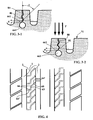
- the figure 3-1 shows in section a variant of a cavity type Helmholtz resonator according to the invention
- the Figure 3-2 shows in section the variant of the figure 3-1 under the action of the contact pressures with the roadway;
- the figure 4 shows another variant of the tread according to the invention.
- the tread 1 shown in a partial view in elevation with the figure 1 comprises four main grooves 2 of circumferential orientation (that is to say longitudinal), these grooves 2 having substantially the same average depth H.
- These circumferential orientation grooves define three ribs 3 and edge portions 30. These edge portions of the tread are provided with oblique transverse grooves 4 delimiting with a circumferential groove a plurality of blocks 5.
- the outer surfaces 31 of the ribs and 51 visible blocks on this figure 1 form a rolling surface 11 intended to come into contact with the road during the rolling of a tire provided with such a strip.
- This tread further comprises a plurality of rubber pads 22 formed by molding on the bottom 21 of the circumferential grooves 2; these pads are usual devices for indicating the maximum level of wear of the tread from which it is necessary to change the tire.
- One of these pads 22 is shown in section on the figure 2-2 this stud has a height h measured relative to the bottom of the groove 2 of depth H.
- each cavity 6 shown in broken lines, forms a Helmholtz resonator of total length Lc and is formed of a first cavity portion 60, of a total length L and of volume V, and of a second cavity portion 70 of medium section s and length 1, this second portion 70, of reduced section relative to the mean section of the first cavity portion 60, opening into a circumferential groove 2.
- the average section s of this second cavity portion 70 is less than the average section S of the first cavity portion 60.
- the respective volumes of the first and second portions of the cavity 6 are accurately determined to attenuate the resonances in the groove for a frequency determined according to the groove length. in the contact with the road which is itself a function of the load supported by the tire and its inflation pressure.
- section is meant here the cross sectional area of the cavity portion considered.
- Each first cavity portion 60 comprises a circumferential portion 63 oriented in the circumferential direction, this portion being terminated by a closed end 61, that is to say not open to the air and an oblique portion 64 ending in an end 62; this oblique portion 64 is extended at one end by the cavity portion 70 of reduced section and opening into a groove 2.
- all the cavities 60 formed on the same rib 3 open into the same circumferential groove 2 and are intended to limit the resonance phenomena in said groove when passing into the contact with the roadway.
- Each cavity 60 as shown in figure 2-1 (representing a section along the line 1-1 of the band of the figure 1 ), has a cross-sectional cross-section of section S whose points 65 of said outermost section (in the direction of the running surface) are at a distance D from the running surface 11 which is greater than the difference between the depth H of the groove 2 and the height h of the stud 22.
- the cavities 60 appear on the running surface after wear at least equal to 2/3 of the initial thickness of the tread.
- the cavities may at the end of use form new grooves or at least form new edges useful for increasing the grip of the tread on the road.
- each cavity 6 formed of the first cavity portion 60 and the second cavity portion 70 is extended along its length Lc by an incision 80 extending radially outwardly to open on the rolling surface 11; each incision 80 comprises an incision portion originating on the cavity and, making an angle A of at least 10 degrees (in this case, the angle A is equal to 15 degrees), with a perpendicular to the surface of rolling and passing through the point of intersection of the incision 80 with the cavity 6, so that the incision 80 closes at least in the vicinity of the cavity to achieve the conservation of the total volume V of said cavity during the passage of said cavity 6 in the contact with the roadway.
- the incision (80) has an average width of less than 1 mm and even more preferentially less than 0.6 mm. With this feature, it is possible to provide an anti-noise effect for frequencies chosen in advance.
- the first cavity portions 60 shown here have a circular section: of course, any other cross sectional shape may be employed. Similarly all the cavities shown in this first variant are of substantially identical geometric characteristics: it is of course possible for the person skilled in the art to better adapt the dimensions of the cavities to adjust the noise generated by the circulation of the air in a chamber. groove and those of other cavities to adjust the noise generated by the flow of air into another groove.
- the cavities opening into a groove can be chosen in such a way that some of them are effective for a given frequency and the other cavities opening in the same groove are effective for another frequency.
- the figure 2-2 shows a section of the tread shown at figure 1 along a line II-II.
- this figure there is a wall of material delimiting a depth groove H, this groove having a pad 22 of height h (defining a legal limit of wear of the tread).
- This second cavity portion 70 has a truncated circular cross section whose area is less than half the cross-sectional area of the first cavity portion 60.
- This second cavity portion is extended in the direction of the tread surface 31 through the incision 80, the connection being made by the incision portion 81 making an angle A with a perpendicular to the running surface.
- substantially all the volume Vc of the cavity 6 (equal to the sum of the volume of the first and the volume of the second cavity portion) is radially below the level of the wear indicator and therefore in this variant said volume Vc is not affected by the wear of the strip. This makes it possible to maintain the same volume of cavity during the entire duration of use of the tire and thus to remain effective to attenuate the noises related to the resonances in the grooves.
- the blade comprises a non-inclined incision portion connecting to the body substantially perpendicular to said body.
- the total useful volume Vc of the cavity further comprises the volume of the non-inclined portion of the incision as shown in FIG. figure 3-1 .
- FIG. figure 3-1 showing a cross section of a cavity variant, there is a portion of circular section 661 extended by an incision portion 662 not inclined to a height d.
- the useful volume of the cavity here comprises the volume of the portion of circular section 661 to which is added the volume of the non-inclined incision portion 662.
- the non-inclined incision portion 662 is extended by the incision 80 and in particular by an inclined portion 81 making an angle A greater than 10 degrees.
- the same cavity is shown when the tread is subjected to contact pressures against the roadway. Under the action of the contact pressures (visualized by the arrows F ), the cavity of volume Vc is isolated since the part incision incision 81 extending said cavity closes and thus said volume Vc is kept constant.
- the cavities comprise two bent portions 66 so as to achieve an optimized occupation of the tread.
- the first part of the cavity 60 comprises two obliquely oriented parts 64, 64 'positioned on either side of the part oriented in the circumferential direction 63.
- the second cavity portion 70 opening into a groove may have a section of shape any.
- Each resonator can be made with specific dimensions including in particular the deformations of the material constituting the tread. It is also possible to provide frequency-shifted resonators so as to be linked, for example, to the tread patterns of the tread. Similarly, what has been presented for tires for passenger vehicles can be applied to any other type of tire and especially those intended for heavy goods vehicles.
Landscapes
- Engineering & Computer Science (AREA)
- Mechanical Engineering (AREA)
- Tires In General (AREA)
- Basic Packing Technique (AREA)
- Package Frames And Binding Bands (AREA)
Claims (5)
- Luftreifen, der einen Scheitelbereich aufweist, welcher axial zu beiden Seiten von Flanken verlängert wird, wobei dieser Scheitelbereich eine Verstärkungsbewehrung enthält, die von einer Vielzahl von in ein Kautschukmaterial eingebetteten Verstärkungen gebildet wird, wobei radial über dieser Verstärkungsbewehrung ein Laufstreifen liegt, von dem eine radial äußere Fläche eine Lauffläche (11) bildet und dazu bestimmt ist, während des Rollens des Luftreifens mit der Straße in Kontakt zu kommen, wobei dieser Laufstreifen eine Vielzahl von Rillen mit allgemeiner Umfangsausrichtung (2) und mit einer Tiefe H enthält, wobei diese Rillen (2) eine Vielzahl von Gummielementen (3, 30) begrenzen, die in Umfangsrichtung angeordnet sind, wobei mindestens ein Gummielement (3, 30) des Laufstreifens eine Vielzahl von Hohlräumen (6) enthält, wobei jeder Hohlraum (6) mit einem Volumen Vc eine allgemein längliche Form einer Gesamtlänge Lc hat, die vorgesehen ist, um in einer einzigen Rille (2) einer allgemeinen Umfangsausrichtung zu münden, wobei jeder Hohlraum (6) über seine ganze Länge Lc von einem Einschnitt (80) verlängert wird, der sich radial nach außen erstreckt, um an der Lauffläche (11) zu münden, wobei dieser Luftreifen dadurch gekennzeichnet ist, dass diese Hohlräume Helmholtzresonatoren bilden, wobei jeder der Hohlräume einen ersten Bereich (60) mit einer Länge L und mit einem mittleren Querschnitt S und einen zweiten Bereich (70) enthält, der einen Kanal mit einer Länge 1 und mit einem Querschnitt s geringer als der mittlere Querschnitt des ersten Bereichs bildet, wobei dieser zweite Bereich (70) an den ersten Bereich (60) anschließt und in einer Rille mündet, wobei das Volumen Vc des Hohlraums gleich der Summe der Volumen des ersten Bereichs (60) und des zweiten Bereichs (70) ist, und dass der Einschnitt (80) einen Einschnittabschnitt (81) enthält, der am Hohlraum beginnt und einen Winkel A von mindestens 10 Grad mit einer Lotrechten zur Lauffläche und durch den Schnittpunkt des Einschnitts mit dem Hohlraum verlaufend bildet, damit der Einschnitt (80) sich zumindest in der Nähe des Hohlraums (6) schließt, um die Beibehaltung des Gesamtvolumens Vc des Hohlraums (6) während des Übergangs des Hohlraums (6) in den Kontakt mit der Straße zu realisieren.
- Luftreifen nach Anspruch 1, dadurch gekennzeichnet, dass der erste Bereich (60) mindestens eines einen Helmholtzresonator bildenden Hohlraums (6) einen Hohlraumbereich (63) enthält, der in Umfangsrichtung ausgerichtet ist.
- Luftreifen nach Anspruch 2, dadurch gekennzeichnet, dass der erste Bereich (60) des Hohlraums außer einem Bereich im Wesentlichen parallel zur Umfangsrichtung zwei Bereiche mit im Wesentlichen schräger Ausrichtung (64', 64") enthält, die zu beiden Seiten des in Umfangsrichtung ausgerichteten Bereichs (63) positioniert sind.
- Luftreifen nach einem der Ansprüche 1 bis 3, dadurch gekennzeichnet, dass, da der Laufstreifen mit einer Verschleißanzeige (22) am Boden mindestens einer Rille (2) versehen ist, wobei diese Verschleißanzeige (22) eine Höhe h gemessen bezüglich des Bodens der Rille hat, jeder einen Helmholtzresonator bildende Hohlraum (6) vollständig in einer Tiefe angeordnet ist, die mindestens gleich der Tiefe der Rillen (2) verringert um die Höhe h der Verschleißanzeige ist.
- Luftreifen nach einem der Ansprüche 1 bis 4, dadurch gekennzeichnet, dass der Einschnitt (80) eine mittlere Breite von weniger als 0,6 mm hat.
Applications Claiming Priority (2)
| Application Number | Priority Date | Filing Date | Title |
|---|---|---|---|
| FR0850107A FR2926037B1 (fr) | 2008-01-09 | 2008-01-09 | Dispositif pour bande de roulement. |
| PCT/EP2009/050182 WO2009095288A1 (fr) | 2008-01-09 | 2009-01-08 | Dispositif pour bande de roulement |
Publications (2)
| Publication Number | Publication Date |
|---|---|
| EP2240335A1 EP2240335A1 (de) | 2010-10-20 |
| EP2240335B1 true EP2240335B1 (de) | 2011-06-29 |
Family
ID=39607941
Family Applications (1)
| Application Number | Title | Priority Date | Filing Date |
|---|---|---|---|
| EP09705659A Active EP2240335B1 (de) | 2008-01-09 | 2009-01-08 | Pneumatischer reifen |
Country Status (8)
| Country | Link |
|---|---|
| US (1) | US8770240B2 (de) |
| EP (1) | EP2240335B1 (de) |
| JP (1) | JP5342565B2 (de) |
| CN (2) | CN101890882B (de) |
| AT (1) | ATE514576T1 (de) |
| EA (1) | EA017520B1 (de) |
| FR (1) | FR2926037B1 (de) |
| WO (1) | WO2009095288A1 (de) |
Families Citing this family (52)
| Publication number | Priority date | Publication date | Assignee | Title |
|---|---|---|---|---|
| JP2010018092A (ja) * | 2008-07-09 | 2010-01-28 | Bridgestone Corp | 空気入りタイヤ |
| FR2953164B1 (fr) | 2009-12-02 | 2012-01-06 | Michelin Soc Tech | Procede de detection de l'usure d'un pneumatique |
| FR2954225B1 (fr) * | 2009-12-18 | 2012-05-11 | Michelin Soc Tech | Pneumatique munis de temoins d'usure sonores multiniveaux |
| EP2517901B1 (de) * | 2009-12-25 | 2016-06-15 | Compagnie Générale des Etablissements Michelin | Luftreifenprofil |
| FR2966083B1 (fr) * | 2010-10-14 | 2012-10-26 | Michelin Soc Tech | Perfectionnement aux dispositifs attenuateurs de bruit pour pneu |
| DE102011056427A1 (de) * | 2011-12-14 | 2013-06-20 | Continental Reifen Deutschland Gmbh | Fahrzeugluftreifen für Nutzfahrzeuge |
| US9434211B2 (en) | 2012-04-30 | 2016-09-06 | Michelin Recherche Et Technique S.A. | Layered tire tread design for improved coast by noise and traction performance |
| US9783004B2 (en) | 2012-04-30 | 2017-10-10 | Compagnie Generale Des Etablissements Michelin | Layered tire tread design with bridged circumferential and transverse grooves |
| JP6411007B2 (ja) * | 2012-05-29 | 2018-10-24 | 株式会社ブリヂストン | 空気入りタイヤ |
| DE102012108384A1 (de) * | 2012-09-10 | 2014-03-13 | Continental Reifen Deutschland Gmbh | Fahrzeugluftreifen |
| FR2998512B1 (fr) * | 2012-11-29 | 2016-07-22 | Michelin & Cie | Bande de roulement de pneumatique a sculpture directionnelle |
| JP6130760B2 (ja) * | 2013-09-11 | 2017-05-17 | 住友ゴム工業株式会社 | 空気入りタイヤ |
| EP3074215A1 (de) * | 2013-11-26 | 2016-10-05 | Compagnie Générale des Etablissements Michelin | Verfahren zur herstellung eines reifen mit dickenfreier lamelle und damit hergestellter reifen |
| EP3200987B1 (de) | 2014-09-30 | 2020-01-15 | Compagnie Générale des Etablissements Michelin | Versteifungen für formgebungselemente zum formen von feineinschnitten |
| JP2018500240A (ja) * | 2014-12-26 | 2018-01-11 | コンパニー ゼネラール デ エタブリッスマン ミシュラン | 回転騒音を減衰させるためのタイヤ |
| FR3034355B1 (fr) * | 2015-03-31 | 2018-07-27 | Compagnie Generale Des Etablissements Michelin | Bande de roulement pour pneumatique comportant des canaux |
| WO2017058224A1 (en) | 2015-09-30 | 2017-04-06 | Compagnie Generale Des Etablissements Michelin | Egg crate sidewall features for sipes |
| WO2017058226A1 (en) | 2015-09-30 | 2017-04-06 | Compagnie Generale Des Etablissements Michelin | Variable thickness sipes |
| FR3045471B1 (fr) * | 2015-12-16 | 2017-12-22 | Michelin & Cie | Pneumatique presentant des proprietes d'usure et de resistance au roulement ameliorees |
| FR3045479B1 (fr) * | 2015-12-16 | 2017-12-22 | Michelin & Cie | Pneumatique presentant des proprietes d'usure et de resistance au roulement ameliorees |
| FR3045490B1 (fr) * | 2015-12-16 | 2017-12-22 | Michelin & Cie | Pneumatique presentant des proprietes d'usure ameliorees |
| FR3045467B1 (fr) * | 2015-12-16 | 2017-12-22 | Michelin & Cie | Pneumatique presentant des proprietes d'usure et de resistance au roulement ameliorees |
| FR3045491B1 (fr) * | 2015-12-16 | 2017-12-22 | Michelin & Cie | Pneumatique presentant des proprietes d'usure ameliorees |
| FR3045474B1 (fr) * | 2015-12-16 | 2017-12-22 | Michelin & Cie | Pneumatique presentant des proprietes d'usure et de resistance au roulement ameliorees |
| EP3858589B1 (de) * | 2015-12-29 | 2024-01-31 | Bridgestone Americas Tire Operations, LLC | Reifen mit geformter lauffläche |
| JP6900544B2 (ja) * | 2016-04-05 | 2021-07-07 | 株式会社ブリヂストン | タイヤ |
| JP6828496B2 (ja) * | 2017-02-17 | 2021-02-10 | 横浜ゴム株式会社 | 空気入りタイヤ |
| JP6828495B2 (ja) * | 2017-02-17 | 2021-02-10 | 横浜ゴム株式会社 | 空気入りタイヤ |
| FR3063454A1 (fr) * | 2017-03-03 | 2018-09-07 | Compagnie Generale Des Etablissements Michelin | Bande de roulement de pneu pour vehicule remorque poids lourd |
| DE102017206731A1 (de) * | 2017-04-21 | 2018-10-25 | Continental Reifen Deutschland Gmbh | Fahrzeugluftreifen mit einem eine Kontaktfläche umfassenden Laufstreifen, wobei der Laufstreifen mindestens einen Feineinschnitt in einem Profilblockelement aufweist |
| JP7092467B2 (ja) * | 2017-06-16 | 2022-06-28 | 株式会社ブリヂストン | タイヤ |
| EP3725556B1 (de) | 2017-12-13 | 2023-09-06 | Bridgestone Corporation | Luftreifen |
| EP3725555B1 (de) * | 2017-12-13 | 2024-02-21 | Bridgestone Corporation | Luftreifen |
| WO2019122677A1 (fr) * | 2017-12-19 | 2019-06-27 | Compagnie Generale Des Etablissements Michelin | Bande de roulement de pneu comprenant des rainures ondulantes |
| JP7069709B2 (ja) * | 2017-12-27 | 2022-05-18 | 住友ゴム工業株式会社 | タイヤ |
| JP7069710B2 (ja) * | 2017-12-27 | 2022-05-18 | 住友ゴム工業株式会社 | タイヤ |
| JP7144206B2 (ja) * | 2018-06-18 | 2022-09-29 | 株式会社ブリヂストン | タイヤ |
| JP7033503B2 (ja) * | 2018-06-18 | 2022-03-10 | 株式会社ブリヂストン | タイヤ |
| JP6980605B2 (ja) * | 2018-06-25 | 2021-12-15 | 株式会社ブリヂストン | タイヤ |
| JP7057234B2 (ja) * | 2018-06-25 | 2022-04-19 | 株式会社ブリヂストン | タイヤ |
| JP7152361B2 (ja) * | 2019-06-14 | 2022-10-12 | 株式会社ブリヂストン | 空気入りタイヤ |
| WO2020262596A1 (en) * | 2019-06-26 | 2020-12-30 | Compagnie Generale Des Etablissements Michelin | A noise improving tread |
| KR102267902B1 (ko) * | 2019-11-12 | 2021-06-24 | 한국타이어앤테크놀로지 주식회사 | 소음 저감을 위한 공명기를 갖는 타이어 |
| JP7306976B2 (ja) * | 2019-12-05 | 2023-07-11 | 株式会社ブリヂストン | 空気入りタイヤ |
| KR102610694B1 (ko) * | 2021-02-10 | 2023-12-07 | 한국타이어앤테크놀로지 주식회사 | 비노출형 마모인디케이터를 가지는 타이어 |
| DE102021206775A1 (de) * | 2021-06-29 | 2022-12-29 | Continental Reifen Deutschland Gmbh | Fahrzeugluftreifen |
| CN115230403B (zh) * | 2022-08-09 | 2024-01-05 | 江苏大学 | 一种具有减振功能的仿生轮胎花纹结构 |
| FR3159557A1 (fr) | 2024-02-23 | 2025-08-29 | Compagnie Generale Des Etablissements Michelin | Pneumatique comprenant une bande de roulement complexe à interface endurante |
| FR3159556A1 (fr) | 2024-02-23 | 2025-08-29 | Compagnie Generale Des Etablissements Michelin | Pneumatique comprenant une bande de roulement complexe résistante à l’usure |
| FR3159555B1 (fr) | 2024-02-23 | 2026-01-16 | Michelin & Cie | Pneumatique comprenant une bande de roulement complexe comprenant des découpures pontées et inclinées |
| FR3161386A1 (fr) | 2024-04-18 | 2025-10-24 | Compagnie Generale Des Etablissements Michelin | Pneumatique à bonne adhérence sur sol mouillé et à grande longévité |
| FR3161387A1 (fr) | 2024-04-18 | 2025-10-24 | Compagnie Generale Des Etablissements Michelin | Pneumatique comprenant un sous-creux réduit et une bande de roulement silencieuse |
Family Cites Families (17)
| Publication number | Priority date | Publication date | Assignee | Title |
|---|---|---|---|---|
| AT403456B (de) * | 1993-05-18 | 1998-02-25 | Semperit Ag | Fahrzeugluftreifen mit einem laufstreifen |
| FR2763892A1 (fr) * | 1997-05-30 | 1998-12-04 | Michelin & Cie | Sculpture et moule pour bande de roulement de pneumatique |
| GB2329161A (en) * | 1997-09-13 | 1999-03-17 | Sumitomo Rubber Ind | Vehicle tyre treads |
| JP3822338B2 (ja) * | 1997-11-19 | 2006-09-20 | 株式会社ブリヂストン | 空気入りタイヤ |
| EP0989000A3 (de) * | 1998-09-24 | 2002-02-06 | Continental Aktiengesellschaft | Luftreifen mit schallabsorbierenden Eigenschaften |
| JP2001063323A (ja) * | 1999-08-26 | 2001-03-13 | Yokohama Rubber Co Ltd:The | 空気入りタイヤ |
| JP4327962B2 (ja) * | 1999-11-04 | 2009-09-09 | 株式会社ブリヂストン | 空気入りタイヤ |
| JP2001239809A (ja) * | 1999-12-21 | 2001-09-04 | Bridgestone Corp | 低騒音空気入りタイヤ |
| JP2001191734A (ja) * | 2000-01-12 | 2001-07-17 | Bridgestone Corp | 重荷重用空気入りタイヤ |
| DE60108972T2 (de) * | 2000-11-13 | 2005-12-29 | Société de Technologie Michelin | Reifenlauffläche und formelement eines formwerkzeugs für eine solche lauffläche |
| DE60209956T2 (de) | 2001-05-14 | 2006-11-30 | Société de Technologie Michelin | Lauffläche mit neigungsvariablen Feineinschnitten enthaltenden Rippen |
| JP4216545B2 (ja) * | 2001-09-17 | 2009-01-28 | 株式会社ブリヂストン | 空気入りタイヤ |
| CN101531123B (zh) * | 2003-05-21 | 2011-01-05 | 株式会社普利司通 | 充气轮胎及设计其胎面花纹的方法 |
| JP2006341816A (ja) * | 2005-06-10 | 2006-12-21 | Bridgestone Corp | 空気入りタイヤ |
| JP2007237816A (ja) * | 2006-03-06 | 2007-09-20 | Bridgestone Corp | 空気入りタイヤ |
| CN101437697B (zh) * | 2006-03-31 | 2011-05-11 | 株式会社普利司通 | 充气轮胎 |
| JP5366539B2 (ja) * | 2006-03-31 | 2013-12-11 | 株式会社ブリヂストン | 空気入りタイヤ |
-
2008
- 2008-01-09 FR FR0850107A patent/FR2926037B1/fr not_active Expired - Fee Related
-
2009
- 2009-01-08 WO PCT/EP2009/050182 patent/WO2009095288A1/fr not_active Ceased
- 2009-01-08 EP EP09705659A patent/EP2240335B1/de active Active
- 2009-01-08 CN CN201010255832.XA patent/CN101890882B/zh not_active Expired - Fee Related
- 2009-01-08 AT AT09705659T patent/ATE514576T1/de not_active IP Right Cessation
- 2009-01-08 JP JP2010541785A patent/JP5342565B2/ja not_active Expired - Fee Related
- 2009-01-08 US US12/812,420 patent/US8770240B2/en active Active
- 2009-01-08 CN CN200980101887.0A patent/CN101909906B/zh not_active Expired - Fee Related
- 2009-01-08 EA EA201070828A patent/EA017520B1/ru not_active IP Right Cessation
Also Published As
| Publication number | Publication date |
|---|---|
| CN101890882B (zh) | 2012-10-10 |
| FR2926037A1 (fr) | 2009-07-10 |
| JP5342565B2 (ja) | 2013-11-13 |
| EA017520B1 (ru) | 2013-01-30 |
| FR2926037B1 (fr) | 2009-12-18 |
| JP2011509213A (ja) | 2011-03-24 |
| CN101909906B (zh) | 2012-10-10 |
| CN101890882A (zh) | 2010-11-24 |
| ATE514576T1 (de) | 2011-07-15 |
| US8770240B2 (en) | 2014-07-08 |
| EP2240335A1 (de) | 2010-10-20 |
| CN101909906A (zh) | 2010-12-08 |
| EA201070828A1 (ru) | 2010-12-30 |
| US20110017374A1 (en) | 2011-01-27 |
| WO2009095288A1 (fr) | 2009-08-06 |
Similar Documents
| Publication | Publication Date | Title |
|---|---|---|
| FR2926037A1 (fr) | Dispositif pour bande de roulement. | |
| EP2627524B1 (de) | Verbesserte geräuschdämpfer für reifen | |
| EP2525988B1 (de) | Reifenlauffläche mit verbesserter geräuschsreduktionsvorrichtung | |
| EP2013037B1 (de) | Sperrteile umfassender laufstreifeneinschnitt | |
| EP3439898B1 (de) | Reifenlauffläche | |
| EP2780178B1 (de) | Vorrichtung zur resonanzrauschunterdrückung für reifen | |
| EP3648991B1 (de) | Reifen dessen lauffläche wellenförmige nuten aufweist | |
| WO2012004285A1 (fr) | Dispositif de protection de bande de roulement | |
| EP3833552B1 (de) | Reifenlauffläche | |
| EP3562689A1 (de) | Lauffläche für einen schwerlastfahrzeugreifen | |
| EP2849956A1 (de) | Verbesserte lärmschutzvorrichtung für reifen | |
| EP3292004A1 (de) | Reifenlauffläche mit einem block mit einer vielzahl von ausschnitten | |
| EP1097826A1 (de) | Laufflächenprofil | |
| FR2983431A1 (fr) | Dispositif reducteur de bruit ameliore pour pneu | |
| EP3898281B1 (de) | Lauffläche mit durch versetzte öffnungen erweiterten verborgenen hohlräumen | |
| EP3681737B1 (de) | Form für eine reifenlauffläche mit verdeckten kanälen | |
| EP3898279B1 (de) | Lauffläche mit verborgenen vertiefungen und nuten | |
| EP3898283A1 (de) | Reifenlauffläche für einen lkw-reifen mit verbesserten einschnitten | |
| WO2020128281A1 (fr) | Bande de roulement de pneu pour poids lourd ayant des incisions ameliorees | |
| WO2020128235A1 (fr) | Bande de roulement comportant des cavites cachees et des rainures | |
| FR3016553A1 (fr) | Dispositif anti bruit nervure pour pneu | |
| FR3013260A1 (fr) | Dispositif anti bruit ameliore pour pneu |
Legal Events
| Date | Code | Title | Description |
|---|---|---|---|
| PUAI | Public reference made under article 153(3) epc to a published international application that has entered the european phase |
Free format text: ORIGINAL CODE: 0009012 |
|
| 17P | Request for examination filed |
Effective date: 20100809 |
|
| AK | Designated contracting states |
Kind code of ref document: A1 Designated state(s): AT BE BG CH CY CZ DE DK EE ES FI FR GB GR HR HU IE IS IT LI LT LU LV MC MK MT NL NO PL PT RO SE SI SK TR |
|
| AX | Request for extension of the european patent |
Extension state: AL BA RS |
|
| GRAP | Despatch of communication of intention to grant a patent |
Free format text: ORIGINAL CODE: EPIDOSNIGR1 |
|
| RTI1 | Title (correction) |
Free format text: PNEUMATIC TIRE |
|
| DAX | Request for extension of the european patent (deleted) | ||
| GRAS | Grant fee paid |
Free format text: ORIGINAL CODE: EPIDOSNIGR3 |
|
| GRAA | (expected) grant |
Free format text: ORIGINAL CODE: 0009210 |
|
| AK | Designated contracting states |
Kind code of ref document: B1 Designated state(s): AT BE BG CH CY CZ DE DK EE ES FI FR GB GR HR HU IE IS IT LI LT LU LV MC MK MT NL NO PL PT RO SE SI SK TR |
|
| REG | Reference to a national code |
Ref country code: GB Ref legal event code: FG4D Free format text: NOT ENGLISH |
|
| REG | Reference to a national code |
Ref country code: CH Ref legal event code: EP |
|
| REG | Reference to a national code |
Ref country code: IE Ref legal event code: FG4D Free format text: LANGUAGE OF EP DOCUMENT: FRENCH |
|
| REG | Reference to a national code |
Ref country code: DE Ref legal event code: R096 Ref document number: 602009001690 Country of ref document: DE Effective date: 20110908 |
|
| REG | Reference to a national code |
Ref country code: NL Ref legal event code: VDEP Effective date: 20110629 |
|
| PG25 | Lapsed in a contracting state [announced via postgrant information from national office to epo] |
Ref country code: HR Free format text: LAPSE BECAUSE OF FAILURE TO SUBMIT A TRANSLATION OF THE DESCRIPTION OR TO PAY THE FEE WITHIN THE PRESCRIBED TIME-LIMIT Effective date: 20110629 Ref country code: NO Free format text: LAPSE BECAUSE OF FAILURE TO SUBMIT A TRANSLATION OF THE DESCRIPTION OR TO PAY THE FEE WITHIN THE PRESCRIBED TIME-LIMIT Effective date: 20110929 Ref country code: SE Free format text: LAPSE BECAUSE OF FAILURE TO SUBMIT A TRANSLATION OF THE DESCRIPTION OR TO PAY THE FEE WITHIN THE PRESCRIBED TIME-LIMIT Effective date: 20110629 Ref country code: LT Free format text: LAPSE BECAUSE OF FAILURE TO SUBMIT A TRANSLATION OF THE DESCRIPTION OR TO PAY THE FEE WITHIN THE PRESCRIBED TIME-LIMIT Effective date: 20110629 |
|
| PG25 | Lapsed in a contracting state [announced via postgrant information from national office to epo] |
Ref country code: SI Free format text: LAPSE BECAUSE OF FAILURE TO SUBMIT A TRANSLATION OF THE DESCRIPTION OR TO PAY THE FEE WITHIN THE PRESCRIBED TIME-LIMIT Effective date: 20110629 Ref country code: AT Free format text: LAPSE BECAUSE OF FAILURE TO SUBMIT A TRANSLATION OF THE DESCRIPTION OR TO PAY THE FEE WITHIN THE PRESCRIBED TIME-LIMIT Effective date: 20110629 Ref country code: LV Free format text: LAPSE BECAUSE OF FAILURE TO SUBMIT A TRANSLATION OF THE DESCRIPTION OR TO PAY THE FEE WITHIN THE PRESCRIBED TIME-LIMIT Effective date: 20110629 Ref country code: GR Free format text: LAPSE BECAUSE OF FAILURE TO SUBMIT A TRANSLATION OF THE DESCRIPTION OR TO PAY THE FEE WITHIN THE PRESCRIBED TIME-LIMIT Effective date: 20110930 Ref country code: FI Free format text: LAPSE BECAUSE OF FAILURE TO SUBMIT A TRANSLATION OF THE DESCRIPTION OR TO PAY THE FEE WITHIN THE PRESCRIBED TIME-LIMIT Effective date: 20110629 |
|
| REG | Reference to a national code |
Ref country code: IE Ref legal event code: FD4D |
|
| PG25 | Lapsed in a contracting state [announced via postgrant information from national office to epo] |
Ref country code: NL Free format text: LAPSE BECAUSE OF FAILURE TO SUBMIT A TRANSLATION OF THE DESCRIPTION OR TO PAY THE FEE WITHIN THE PRESCRIBED TIME-LIMIT Effective date: 20110629 Ref country code: CZ Free format text: LAPSE BECAUSE OF FAILURE TO SUBMIT A TRANSLATION OF THE DESCRIPTION OR TO PAY THE FEE WITHIN THE PRESCRIBED TIME-LIMIT Effective date: 20110629 Ref country code: IE Free format text: LAPSE BECAUSE OF FAILURE TO SUBMIT A TRANSLATION OF THE DESCRIPTION OR TO PAY THE FEE WITHIN THE PRESCRIBED TIME-LIMIT Effective date: 20110629 Ref country code: PT Free format text: LAPSE BECAUSE OF FAILURE TO SUBMIT A TRANSLATION OF THE DESCRIPTION OR TO PAY THE FEE WITHIN THE PRESCRIBED TIME-LIMIT Effective date: 20111031 Ref country code: IS Free format text: LAPSE BECAUSE OF FAILURE TO SUBMIT A TRANSLATION OF THE DESCRIPTION OR TO PAY THE FEE WITHIN THE PRESCRIBED TIME-LIMIT Effective date: 20111029 Ref country code: EE Free format text: LAPSE BECAUSE OF FAILURE TO SUBMIT A TRANSLATION OF THE DESCRIPTION OR TO PAY THE FEE WITHIN THE PRESCRIBED TIME-LIMIT Effective date: 20110629 |
|
| PG25 | Lapsed in a contracting state [announced via postgrant information from national office to epo] |
Ref country code: CY Free format text: LAPSE BECAUSE OF FAILURE TO SUBMIT A TRANSLATION OF THE DESCRIPTION OR TO PAY THE FEE WITHIN THE PRESCRIBED TIME-LIMIT Effective date: 20110629 Ref country code: SK Free format text: LAPSE BECAUSE OF FAILURE TO SUBMIT A TRANSLATION OF THE DESCRIPTION OR TO PAY THE FEE WITHIN THE PRESCRIBED TIME-LIMIT Effective date: 20110629 Ref country code: PL Free format text: LAPSE BECAUSE OF FAILURE TO SUBMIT A TRANSLATION OF THE DESCRIPTION OR TO PAY THE FEE WITHIN THE PRESCRIBED TIME-LIMIT Effective date: 20110629 |
|
| PLBE | No opposition filed within time limit |
Free format text: ORIGINAL CODE: 0009261 |
|
| STAA | Information on the status of an ep patent application or granted ep patent |
Free format text: STATUS: NO OPPOSITION FILED WITHIN TIME LIMIT |
|
| 26N | No opposition filed |
Effective date: 20120330 |
|
| PG25 | Lapsed in a contracting state [announced via postgrant information from national office to epo] |
Ref country code: DK Free format text: LAPSE BECAUSE OF FAILURE TO SUBMIT A TRANSLATION OF THE DESCRIPTION OR TO PAY THE FEE WITHIN THE PRESCRIBED TIME-LIMIT Effective date: 20110629 |
|
| BERE | Be: lapsed |
Owner name: SOC. DE TECHNOLOGIE MICHELIN Effective date: 20120131 Owner name: MICHELIN RECHERCHE ET TECHNIQUE S.A. Effective date: 20120131 |
|
| REG | Reference to a national code |
Ref country code: DE Ref legal event code: R097 Ref document number: 602009001690 Country of ref document: DE Effective date: 20120330 |
|
| PG25 | Lapsed in a contracting state [announced via postgrant information from national office to epo] |
Ref country code: MC Free format text: LAPSE BECAUSE OF NON-PAYMENT OF DUE FEES Effective date: 20120131 |
|
| PG25 | Lapsed in a contracting state [announced via postgrant information from national office to epo] |
Ref country code: BE Free format text: LAPSE BECAUSE OF NON-PAYMENT OF DUE FEES Effective date: 20120131 |
|
| PG25 | Lapsed in a contracting state [announced via postgrant information from national office to epo] |
Ref country code: MK Free format text: LAPSE BECAUSE OF FAILURE TO SUBMIT A TRANSLATION OF THE DESCRIPTION OR TO PAY THE FEE WITHIN THE PRESCRIBED TIME-LIMIT Effective date: 20110629 |
|
| PG25 | Lapsed in a contracting state [announced via postgrant information from national office to epo] |
Ref country code: ES Free format text: LAPSE BECAUSE OF FAILURE TO SUBMIT A TRANSLATION OF THE DESCRIPTION OR TO PAY THE FEE WITHIN THE PRESCRIBED TIME-LIMIT Effective date: 20111010 |
|
| PG25 | Lapsed in a contracting state [announced via postgrant information from national office to epo] |
Ref country code: BG Free format text: LAPSE BECAUSE OF FAILURE TO SUBMIT A TRANSLATION OF THE DESCRIPTION OR TO PAY THE FEE WITHIN THE PRESCRIBED TIME-LIMIT Effective date: 20110929 |
|
| PG25 | Lapsed in a contracting state [announced via postgrant information from national office to epo] |
Ref country code: MT Free format text: LAPSE BECAUSE OF FAILURE TO SUBMIT A TRANSLATION OF THE DESCRIPTION OR TO PAY THE FEE WITHIN THE PRESCRIBED TIME-LIMIT Effective date: 20110629 |
|
| REG | Reference to a national code |
Ref country code: CH Ref legal event code: PL |
|
| GBPC | Gb: european patent ceased through non-payment of renewal fee |
Effective date: 20130108 |
|
| PG25 | Lapsed in a contracting state [announced via postgrant information from national office to epo] |
Ref country code: CH Free format text: LAPSE BECAUSE OF NON-PAYMENT OF DUE FEES Effective date: 20130131 Ref country code: LI Free format text: LAPSE BECAUSE OF NON-PAYMENT OF DUE FEES Effective date: 20130131 |
|
| PG25 | Lapsed in a contracting state [announced via postgrant information from national office to epo] |
Ref country code: GB Free format text: LAPSE BECAUSE OF NON-PAYMENT OF DUE FEES Effective date: 20130108 |
|
| PG25 | Lapsed in a contracting state [announced via postgrant information from national office to epo] |
Ref country code: TR Free format text: LAPSE BECAUSE OF FAILURE TO SUBMIT A TRANSLATION OF THE DESCRIPTION OR TO PAY THE FEE WITHIN THE PRESCRIBED TIME-LIMIT Effective date: 20110629 |
|
| PG25 | Lapsed in a contracting state [announced via postgrant information from national office to epo] |
Ref country code: LU Free format text: LAPSE BECAUSE OF NON-PAYMENT OF DUE FEES Effective date: 20120108 |
|
| PG25 | Lapsed in a contracting state [announced via postgrant information from national office to epo] |
Ref country code: HU Free format text: LAPSE BECAUSE OF FAILURE TO SUBMIT A TRANSLATION OF THE DESCRIPTION OR TO PAY THE FEE WITHIN THE PRESCRIBED TIME-LIMIT Effective date: 20090108 |
|
| REG | Reference to a national code |
Ref country code: FR Ref legal event code: PLFP Year of fee payment: 8 |
|
| PGFP | Annual fee paid to national office [announced via postgrant information from national office to epo] |
Ref country code: IT Payment date: 20160127 Year of fee payment: 8 |
|
| REG | Reference to a national code |
Ref country code: FR Ref legal event code: PLFP Year of fee payment: 9 |
|
| REG | Reference to a national code |
Ref country code: FR Ref legal event code: PLFP Year of fee payment: 10 |
|
| PG25 | Lapsed in a contracting state [announced via postgrant information from national office to epo] |
Ref country code: IT Free format text: LAPSE BECAUSE OF NON-PAYMENT OF DUE FEES Effective date: 20170108 |
|
| PGFP | Annual fee paid to national office [announced via postgrant information from national office to epo] |
Ref country code: DE Payment date: 20200121 Year of fee payment: 12 |
|
| REG | Reference to a national code |
Ref country code: DE Ref legal event code: R119 Ref document number: 602009001690 Country of ref document: DE |
|
| PG25 | Lapsed in a contracting state [announced via postgrant information from national office to epo] |
Ref country code: DE Free format text: LAPSE BECAUSE OF NON-PAYMENT OF DUE FEES Effective date: 20210803 |
|
| PGFP | Annual fee paid to national office [announced via postgrant information from national office to epo] |
Ref country code: FR Payment date: 20220119 Year of fee payment: 14 |
|
| PG25 | Lapsed in a contracting state [announced via postgrant information from national office to epo] |
Ref country code: FR Free format text: LAPSE BECAUSE OF NON-PAYMENT OF DUE FEES Effective date: 20230131 |