EP2240696B1 - Manchon d'admission pour compresseur axial - Google Patents
Manchon d'admission pour compresseur axial Download PDFInfo
- Publication number
- EP2240696B1 EP2240696B1 EP08872325.9A EP08872325A EP2240696B1 EP 2240696 B1 EP2240696 B1 EP 2240696B1 EP 08872325 A EP08872325 A EP 08872325A EP 2240696 B1 EP2240696 B1 EP 2240696B1
- Authority
- EP
- European Patent Office
- Prior art keywords
- inlet
- bearing
- inlet connector
- housing
- connector according
- Prior art date
- Legal status (The legal status is an assumption and is not a legal conclusion. Google has not performed a legal analysis and makes no representation as to the accuracy of the status listed.)
- Not-in-force
Links
Images

Classifications
-
- F—MECHANICAL ENGINEERING; LIGHTING; HEATING; WEAPONS; BLASTING
- F04—POSITIVE - DISPLACEMENT MACHINES FOR LIQUIDS; PUMPS FOR LIQUIDS OR ELASTIC FLUIDS
- F04D—NON-POSITIVE-DISPLACEMENT PUMPS
- F04D29/00—Details, component parts, or accessories
- F04D29/05—Shafts or bearings, or assemblies thereof, specially adapted for elastic fluid pumps
- F04D29/056—Bearings
- F04D29/059—Roller bearings
-
- F—MECHANICAL ENGINEERING; LIGHTING; HEATING; WEAPONS; BLASTING
- F01—MACHINES OR ENGINES IN GENERAL; ENGINE PLANTS IN GENERAL; STEAM ENGINES
- F01D—NON-POSITIVE DISPLACEMENT MACHINES OR ENGINES, e.g. STEAM TURBINES
- F01D25/00—Component parts, details, or accessories, not provided for in, or of interest apart from, other groups
- F01D25/16—Arrangement of bearings; Supporting or mounting bearings in casings
- F01D25/162—Bearing supports
-
- F—MECHANICAL ENGINEERING; LIGHTING; HEATING; WEAPONS; BLASTING
- F01—MACHINES OR ENGINES IN GENERAL; ENGINE PLANTS IN GENERAL; STEAM ENGINES
- F01D—NON-POSITIVE DISPLACEMENT MACHINES OR ENGINES, e.g. STEAM TURBINES
- F01D9/00—Stators
- F01D9/06—Fluid supply conduits to nozzles or the like
- F01D9/065—Fluid supply or removal conduits traversing the working fluid flow, e.g. for lubrication-, cooling-, or sealing fluids
-
- F—MECHANICAL ENGINEERING; LIGHTING; HEATING; WEAPONS; BLASTING
- F04—POSITIVE - DISPLACEMENT MACHINES FOR LIQUIDS; PUMPS FOR LIQUIDS OR ELASTIC FLUIDS
- F04D—NON-POSITIVE-DISPLACEMENT PUMPS
- F04D19/00—Axial-flow pumps
- F04D19/02—Multi-stage pumps
-
- F—MECHANICAL ENGINEERING; LIGHTING; HEATING; WEAPONS; BLASTING
- F04—POSITIVE - DISPLACEMENT MACHINES FOR LIQUIDS; PUMPS FOR LIQUIDS OR ELASTIC FLUIDS
- F04D—NON-POSITIVE-DISPLACEMENT PUMPS
- F04D29/00—Details, component parts, or accessories
- F04D29/06—Lubrication
- F04D29/063—Lubrication specially adapted for elastic fluid pumps
-
- F—MECHANICAL ENGINEERING; LIGHTING; HEATING; WEAPONS; BLASTING
- F04—POSITIVE - DISPLACEMENT MACHINES FOR LIQUIDS; PUMPS FOR LIQUIDS OR ELASTIC FLUIDS
- F04D—NON-POSITIVE-DISPLACEMENT PUMPS
- F04D29/00—Details, component parts, or accessories
- F04D29/40—Casings; Connections of working fluid
- F04D29/52—Casings; Connections of working fluid for axial pumps
- F04D29/522—Casings; Connections of working fluid for axial pumps especially adapted for elastic fluid pumps
-
- F—MECHANICAL ENGINEERING; LIGHTING; HEATING; WEAPONS; BLASTING
- F04—POSITIVE - DISPLACEMENT MACHINES FOR LIQUIDS; PUMPS FOR LIQUIDS OR ELASTIC FLUIDS
- F04D—NON-POSITIVE-DISPLACEMENT PUMPS
- F04D29/00—Details, component parts, or accessories
- F04D29/60—Mounting; Assembling; Disassembling
- F04D29/64—Mounting; Assembling; Disassembling of axial pumps
- F04D29/644—Mounting; Assembling; Disassembling of axial pumps especially adapted for elastic fluid pumps
-
- F—MECHANICAL ENGINEERING; LIGHTING; HEATING; WEAPONS; BLASTING
- F04—POSITIVE - DISPLACEMENT MACHINES FOR LIQUIDS; PUMPS FOR LIQUIDS OR ELASTIC FLUIDS
- F04D—NON-POSITIVE-DISPLACEMENT PUMPS
- F04D29/00—Details, component parts, or accessories
- F04D29/66—Combating cavitation, whirls, noise, vibration or the like; Balancing
- F04D29/661—Combating cavitation, whirls, noise, vibration or the like; Balancing especially adapted for elastic fluid pumps
- F04D29/668—Combating cavitation, whirls, noise, vibration or the like; Balancing especially adapted for elastic fluid pumps damping or preventing mechanical vibrations
Definitions
- the invention relates to an inlet connection for an axial compressor, in particular a turbocompressor, with an inlet housing, in which a bearing housing is arranged with a first fluid axially in the flow direction of a fluid to be compressed bearing for a rotor of the axial compressor, wherein the bearing housing connected to the inlet housing via an inlet strut is, which is connected in an end cross section with the inlet housing.
- Such intake struts are purely radial in conventional axial compressors, ie. parallel to a normal plane to the longitudinal axis of the inlet nozzle, so that the bearing center of the first or front bearing is arranged axially in the flow direction of a fluid to be compressed substantially at the level of the center of area of this end cross-section, in other words the bearing axially centrally in the inlet strut under the transition is arranged in the inlet housing.
- a piercing point of a bearing axis through a plane of symmetry of a symmetrical bearing, a center of mass of the bearing, the geometric center between the axial end faces of the bearing or a pressure point of the bearing are referred to as the bearing center point.
- the inlet struts in particular for reasons of strength and production, are often connected relatively far forward to the inlet cross-section of the inlet connection with the inlet housing in order to be able to support, for example, against corresponding reinforcements of the inlet housing or to avoid greatly varying wall thicknesses during prototyping, this is also the first one or front bearing arranged correspondingly far forward, so that there is a relatively large bearing distance to a second, rear bearing of the rotor of the axial compressor, which is arranged in the flow direction behind the first bearing.
- one or more fluid passages may be formed.
- Such fluid passages can serve, for example, the lubrication of the bearing and for this purpose open into the bearing housing on the one hand in or near the bearing and on the other hand with a Schmierffenver- or disposal, for example via grease nipples, lines, passages in adjacent housing parts or the like, be connected outside of the inlet housing.
- a Schmierstoffver- or disposal for example via grease nipples, lines, passages in adjacent housing parts or the like, be connected outside of the inlet housing.
- a bearing supplied by the radial fluid passage has to be arranged axially at the level of the outlet opening of the fluid passage from the inlet housing, which also disadvantageously increases the bearing center distance of the rotor.
- a larger bearing center distance can adversely affect the rotor dynamics.
- an inlet nozzle according to the preamble of claim 1 is known. Object of the present invention is therefore to provide an improved inlet nozzle available. To solve this problem, an inlet nozzle according to the preamble of claim 1 is further developed by at least one of its characterizing features.
- Claim 15 provides an axial compressor with such an inlet connection under protection, the dependent claims relate to advantageous developments.
- An inlet connection according to the invention is provided for an axial compressor, in particular a turbocompressor, and may preferably be detachably or fixedly connected or integrally formed therewith. It has an inlet housing, the interior of which preferably tapers in the flow direction of a fluid to be compressed.
- a bearing housing is arranged, which receives a front or first bearing for a rotor of the axial compressor.
- This may in particular be a radial bearing, a thrust bearing or a radial-axial bearing.
- This bearing is axially in the flow direction of a fluid to be compressed, a first, ie front bearing, wherein the rotor in further Bearings can be supported, which have a greater axial distance to an inlet cross-section of the inlet nozzle.
- the bearing housing is supported in the inlet housing via one or more inlet struts.
- inlet struts can be distributed equidistantly over the circumference of the bearing housing or have different angular distances from each other. While equidistantly distributed inlet struts the flow in the bearing housing homogeneous and thus little disturbing, inlet struts with different angular distances to each other can be adapted to constructional boundary conditions of the housing, in particular external leads, ribs, different wall thicknesses or the like.
- One or more inlet struts are connected in each case an end cross section of the corresponding inlet strut with the inlet housing.
- one or more, preferably all inlet struts may be integrally connected to the inlet and / or bearing housing, for example by primary molding.
- one or more inlet struts can also be connected to the entry and / or bearing housing after the prototyping, for example welded or screwed.
- a fluid passage is formed in at least one inlet struts. This can be provided in particular for supplying and / or removing lubricant to the bearing for the impeller.
- a fluid passage can likewise serve for supplying and / or removing cooling fluid, in particular cooling air, and / or a blocking fluid, in particular blocking air, in order to cool the axial compressor or to avoid a lubricant outlet into the axial compressor.
- Other fluids such as a hydraulic fluid, in particular a controlled bearing, can flow through the fluid passage.
- a fluid passage in a preferred embodiment in or in the vicinity of the bearing can open into the bearing housing.
- the fluid passage described so far only for the sake of simplification may, for example, also be designed to guide cables, lines or the like, for example electrical and / or optical lines for sensors in the bearing housing.
- a fluid passage at least partially encloses an acute angle with a normal plane to the longitudinal axis of the inlet nozzle, ie obliquely to the axial direction of the inlet nozzle, in particular from radially outside to radially inside in the direction of flow of the fluid to be compressed.
- the bearing center of the first bearing is in the flow direction of a fluid to be compressed axially at least 0.1 times, preferably at least 0.15 times, more preferably at least 0.2 times and in particular at least 0.25 -fold the chord length of the end cross-section disposed behind the center of area of the end cross-section.
- chord length is the maximum extent of the end cross-section in the axial direction, ie in the flow direction of a fluid to be compressed, which corresponds, for example, to its diameter in the case of a circular end cross-section, and to its large radius in the case of an elliptical cross-section.
- the first bearing is arranged behind the center of area of an end cross-section , This advantageously the bearing distance to the center of mass of the rotor and - if present - shortened to a second, rear bearing of the rotor of the axial compressor, which is arranged downstream of the first bearing in the flow direction.
- the first bearing in particular behind the first two thirds of the chord length, ie at least 0.17-fold, preferably after the first three quarters of the chord length, ie be arranged at least 0.25-fold behind the center of area of the end cross-section.
- the bearing center of the first bearing is axially behind at least 0.1 times, 0.15 times, 0.2 times or 0.25 times the chord length of the end cross section arranged the surface center of the end cross-section of at least one inlet strut.
- inlet struts it is also possible for inlet struts to be present, with respect to whose end cross-section the first bearing is arranged axially in front of or in the center of the surface.
- the bearing center of the first bearing is arranged axially at least 0.1 times, 0.15 times, 0.2 times or 0.25 times the chord length of the end cross section behind the surface centers of the end cross sections of all inlet struts ,
- the bearing center no longer has to lie within the chord length of the end section (s) projected onto the longitudinal axis of the entry socket, but can also be arranged axially behind the end section (s). Equally, however, it can also be located within the chord length of the end cross section projected onto the longitudinal axis of the entry stub, in particular at most 0.75 times, in particular at most 0.5 times the chord length of the end cross section behind the center of the face cross section be.
- first bearing is offset axially to the rear relative to the end cross-section of an inlet strut, it can be operated particularly well by obliquely extending fluid passages in this inlet strut.
- fluid passages can be formed in one or more inlet struts, wherein at least one, preferably several, particularly preferably all fluid passages form an acute angle with a normal plane to the longitudinal axis of the inlet nozzle.
- Such fluid passages may preferably run substantially parallel to one another, which is the production simplified. Likewise, however, they may also include different angles with the normal plane so as to define in particular optimal paths between exit positions on the inlet housing and on the bearing housing. In this way, for example, fluid passages opening into the bearing housing close to one another can be connected to supply lines at the inlet housing that are axially remote from one another, and vice versa.
- fluid passages in two inlet struts may be formed so as to optimally distribute, for example, supply and discharge lines. Also fluid passages in the same or different inlet struts need not have the same diameter, but may, for example, be adapted to the nature and quantity of the added or discharged medium.
- One or more fluid passages may be substantially rectilinear so as to form the same acute angle everywhere with a normal plane to the longitudinal axis of the inlet nozzle. Such fluid passages are particularly easy to produce by drilling and to consider in the design.
- the angle formed by such a substantially rectilinear fluid passage with a normal plane to the longitudinal axis of the inlet nozzle can preferably be in the range between 10 ° and 40 °, in particular in the range between 20 ° and 30 °. This represents a good compromise from shortening the bearing center distance and increasing the manufacturing effort.
- One or more fluid passages may also have a kinked profile, so that at least a portion of this fluid passage forms an acute angle with a normal plane to the longitudinal axis of the inlet nozzle.
- other sections of such fluid passages for example, can extend substantially in the radial direction of the inlet housing. In this way, the advantages of purely radial and inclined fluid passages can be interconnected.
- the angle which forms such an oblique section of a fluid passage with a bent course with a normal plane to the longitudinal axis of the inlet nozzle is preferably in the range between 60 ° and 80 °, in particular in the range between 65 ° and 75 °. Since here only a shorter distance in the radial direction to compensate for the axial offset between inlet and outlet of the fluid passage available stands, such oblique sections preferably have larger angles to the normal plane than kinkless fluid passages.
- two or more fluid passages open into a common portion that communicates with the interior of the bearing housing.
- this section may extend obliquely, while the fluid passages opening into it preferably extend essentially in the radial direction of the inlet housing.
- a radial axis through the center of area or center of gravity of at least one inlet strut can also - at least in sections - form an acute angle with a normal plane to the longitudinal axis of the inlet nozzle.
- an inlet strut having a constant cross section can be inclined overall, in particular in the direction of flow of a fluid to be compressed towards the bearing housing tapering, be formed.
- Such a swept inlet strut is particularly suitable for receiving in particular straight-line fluid passages.
- an inlet strut can also extend substantially in the radial direction of the inlet housing and widen towards the bearing housing, so that the center of area or center of gravity displaced towards the bearing housing in the flow direction of a fluid to be compressed to the rear.
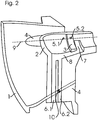
- Fig. 2 shows the cut out lower, seen in the flow direction of a fluid to be compressed left, a quarter of an inlet nozzle according to an embodiment the present invention in perspective view, Fig. 1 a horizontal section in Fig. 2 ,
- the inlet nozzle has an inlet housing 1 for collecting and supplying a medium to a turbo-compressor (not shown).
- a bearing housing 2 is arranged, which has a substantially cylindrical shape, with the medium to be compacted in the flow direction (from left to right in the figures), front hemispherical end face.
- a radial bearing 3 for a rotor with impeller of the turbocompressor (not shown) is formed, the bearing center point 3a is located axially in the center of the bearing ring shown.
- the bearing housing 2 is connected to the inlet housing 1 via three, four or more inlet struts, wherein in Fig. 2 a lower (cut) and a left (partially hidden) inlet strut 4 are visible, in Fig. 1 the left inlet strut 4.
- two or more blind struts are additionally arranged in the upper half of the inlet housing, which are not connected to the bearing housing.
- left inlet strut 4 is integrally connected to the inlet housing 1 and is in its the inlet housing 1 facing end cross section in this over.
- the center of area 10 of this end cross-section is in Fig. 1 drawn and is located axially in front of the bearing center point 3a, which in relation to this area center point by the 0.375-fold in the flow direction of a fluid to be compressed axially to the rear (to the right in Fig. 1 ) is offset.
- Fig. 1 left front fluid passage 5.1 (dash-dot in Fig. 1 ) serves the guidance of lines for sensors to the bearing 3 and in the vicinity of the bearing 3 before this opens into the bearing housing 2
- a middle fluid passage 5.2 (drawn in Fig. 1 ) the supply of lubricant to the bearing 3 and opens in the bearing 3 in the bearing housing 2
- a in Fig. 1 right, rear fluid passage 5.3 (double-dashed in Fig. 1 ) serves the supply of sealing air into the bearing housing 2 and opens in the vicinity of the bearing 3 after this in the bearing housing 2.
- These fluid passages 5 are formed as through-holes and therefore extend substantially straight. They close an acute angle of about 23 ° with a normal plane to the longitudinal axis of the inlet nozzle (vertical plane perpendicular to the plane of the drawing Fig. 1 ) or the complementary angle of about 67 ° with the longitudinal axis.
- two fluid passages 6 are formed, which serve for the removal of lubricant from the interior of the bearing housing 2.
- These fluid passages 6 form sections an acute angle with a normal plane to the longitudinal axis of the inlet nozzle. For this purpose, they have a kinked course, wherein in each case a substantially extending in the radial direction portion 61 and 6.2 merges into a two fluid passages 6 common portion 8, which forms an acute angle of about 72 ° with a normal plane to the longitudinal axis of the inlet nozzle ,
- This common inclined section 8 extends in the longitudinal direction of the inlet housing 1 (from left to right in FIG Fig. 1 ) and ends at the end in a circular segment-shaped annular groove 7, which is formed at right angles to the section 8 and extends over a range of 70 ° in the lower half of the bearing housing 2.
- a circular segment-shaped annular groove 7 which is formed at right angles to the section 8 and extends over a range of 70 ° in the lower half of the bearing housing 2.
- common open portion 8 which extends from the annular groove 7 below the radial bearing 3 forward through to the extending in the radial direction sections 6.1, 6.2, communicate the two fluid passages with the interior of the bearing housing. 2
- the inlet struts 4 extend substantially in the radial direction (from top to bottom in FIG Fig. 1 ).
- the inlet struts 4 at their in the flow direction of the fluid to be compressed (right in Fig. 1 . 2 ) rear trailing edge a substantially dreickförmigen approach 4.1.
- a radial axis through the surface centers of the inlet struts 4 therefore has in this section with the paragraph 4.1 at an acute angle with a normal plane to the longitudinal axis of the inlet nozzle.
Landscapes
- Engineering & Computer Science (AREA)
- Mechanical Engineering (AREA)
- General Engineering & Computer Science (AREA)
- Physics & Mathematics (AREA)
- Fluid Mechanics (AREA)
- Structures Of Non-Positive Displacement Pumps (AREA)
Claims (15)
- Manchon d'admission pour un compresseur axial, notamment un turbocompresseur, comportant un logement d'admission (1), dans lequel un logement de palier (2) avec un premier palier axial (3) dans la direction d'écoulement d'un fluide à compresser, notamment un palier radial et/ou axial, pour un rotor est disposé, dans lequel le logement de palier (1) est relié avec le logement d'admission (1) par l'intermédiaire d'au moins une entretoise d'entrée, qui est reliée dans une section transversale frontale avec le logement d'admission, dans lequel
dans au moins une des entretoises d'entrée (4) au moins un passage de fluide (5,6) est réalisé, qui forme au moins par portions un angle aigu avec un plan normal par rapport à l'angle longitudinal du manchon d'admission, caractérisé en ce que le point central de palier du palier (3) dans la direction d'écoulement est disposé axialement au moins de 0,1 fois la longueur de corde que l'extension maximale de la section transversale frontale dans la direction axiale derrière le point central de surface de la section transversale frontale. - Manchon d'admission selon la revendication 1, caractérisé en ce que le point central de palier du palier (3) dans la direction d'écoulement et disposé axialement au moins de 0,15 fois, notamment au moins de 0,2 fois, notamment au moins de 0,25 fois la longueur de corde de la section transversale frontale derrière le point central de surface de la section transversale frontale.
- Manchon d'admission selon la revendication 1 ou 2, caractérisé en ce que le logement de palier (2) est relié avec le logement d'admission (1) par l'intermédiaire de plusieurs, notamment trois ou quatre entretoises d'entrée.
- Manchon d'admission selon la revendication 3, caractérisé en ce que le logement de palier (3) est relié avec le logement d'admission (1) par l'intermédiaire de trois ou plusieurs entretoises d'entrée réparties uniformément ou non uniformément, dans lequel une ou plusieurs entretoises d'entrée sont configurés comme des entretoises aveugles.
- Manchon d'admission selon une des revendications précédentes, caractérisé en ce que dans au moins une entretoise d'entrée (4), plusieurs, notamment deux ou trois passages de fluide (5.1, 5.2, 5.3 ; 6.1, 6.2) sont réalisés.
- Manchon d'admission selon la revendication 3 et 4, caractérisé en ce que dans une première entretoise d'entrée (4) plusieurs passages de fluide (6.1,6.2) et dans une autre entretoise d'entrée (4) un nombre différent de passages de fluide (5.1, 5.2, 5.3) sont réalisés.
- Manchon d'admission selon une des revendications précédentes, caractérisé en ce que au moins un passage de fluide (5) s'étend essentiellement en ligne droite, de sorte qu'il forme partout le même angle aigu avec un plan normal par rapport à l'axe longitudinal du manchon d'admission.
- Manchon d'admission selon la revendication 6, caractérisé en ce que l'angle qui forme un passage de fluide (5) s'étendant essentiellement en ligne droite avec un plan normal par rapport à l'axe longitudinal du manchon d'admission, se situe dans la plage entre 10° et 40°, notamment dans la plage entre 20° et 30°.
- Manchon d'admission selon une des revendications précédentes, caractérisé en ce que au moins un passage de fluide (6) présente un cours coudé, de sorte que au moins une portion (8) de ce passage de fluide formant un angle aigu avec un plan normal par rapport à l'axe longitudinal du manchon d'admission.
- Manchon d'admission selon la revendication 8, caractérisé en ce que l'angle, qui forme une portion (8) d'un passage de fluide (6) avec un cours coudé avec un plan normal par rapport à l'axe longitudinal du manchon d'admission, se situe dans la plage entre 60° et 80°, notamment dans la plage entre 65° et 75°.
- Manchon d'admission selon une des revendications précédentes, caractérisé en ce que au moins deux passages de fluide (6.1,6.2) débouchent dans une portion commune (8), qui communique avec l'intérieur du logement de palier (2).
- Manchon d'admission selon une des revendications précédentes, caractérisé en ce que un passage de fluide pour alimenter et/ou évacuer du lubrifiant vers le palier (3) pour le rotor est réalisé.
- Manchon d'admission selon une des revendications précédentes, caractérisé en ce que un passage de fluide (5,6) dans ou à proximité du palier (3) débouche dans le logement de palier (2).
- Manchon d'admission selon une des revendications précédentes, caractérisé en ce que un axe radial à travers les points centraux de surface d'au moins une entretoise d'entrée forme au moins par portions un angle aigu avec un plan normal par rapport à l'axe longitudinal du manchon d'admission.
- Compresseur axial, notamment turbocompresseur, comportant un manchon d'admission selon une des revendications précédentes.
Applications Claiming Priority (2)
| Application Number | Priority Date | Filing Date | Title |
|---|---|---|---|
| DE200810008886 DE102008008886A1 (de) | 2008-02-13 | 2008-02-13 | Eintrittsstutzen für einen Axialverdichter |
| PCT/EP2008/009254 WO2009100741A1 (fr) | 2008-02-13 | 2008-11-03 | Manchon d'admission pour compresseur axial |
Publications (2)
| Publication Number | Publication Date |
|---|---|
| EP2240696A1 EP2240696A1 (fr) | 2010-10-20 |
| EP2240696B1 true EP2240696B1 (fr) | 2019-01-02 |
Family
ID=40350157
Family Applications (1)
| Application Number | Title | Priority Date | Filing Date |
|---|---|---|---|
| EP08872325.9A Not-in-force EP2240696B1 (fr) | 2008-02-13 | 2008-11-03 | Manchon d'admission pour compresseur axial |
Country Status (6)
| Country | Link |
|---|---|
| US (1) | US9004856B2 (fr) |
| EP (1) | EP2240696B1 (fr) |
| JP (1) | JP5444254B2 (fr) |
| CN (1) | CN101952604B (fr) |
| DE (1) | DE102008008886A1 (fr) |
| WO (1) | WO2009100741A1 (fr) |
Families Citing this family (1)
| Publication number | Priority date | Publication date | Assignee | Title |
|---|---|---|---|---|
| DE102008008886A1 (de) | 2008-02-13 | 2009-08-20 | Man Turbo Ag | Eintrittsstutzen für einen Axialverdichter |
Citations (1)
| Publication number | Priority date | Publication date | Assignee | Title |
|---|---|---|---|---|
| US2648493A (en) * | 1945-10-23 | 1953-08-11 | Edward A Stalker | Compressor |
Family Cites Families (15)
| Publication number | Priority date | Publication date | Assignee | Title |
|---|---|---|---|---|
| GB583469A (en) * | 1943-01-04 | 1946-12-19 | David Macleish Smith | Improvements in turbo compressors |
| US2665549A (en) * | 1949-11-02 | 1954-01-12 | United Aircraft Corp | Compressor drive and fuel supply for gas turbine power plants |
| DE2242734A1 (de) * | 1972-08-31 | 1974-03-21 | Motoren Turbinen Union | Lagerung fuer waermekraftmaschinen |
| EP0122328B1 (fr) * | 1979-05-14 | 1987-03-25 | OSBORN, Norbert Lewis | Carter de compresseur pour une turbosoufflante ainsi que méthode de production d'un tel carter |
| CN1004016B (zh) * | 1985-04-01 | 1989-04-26 | 苏舍兄弟有限公司 | 涡轮机的筒形外壳 |
| US4868963A (en) * | 1988-01-11 | 1989-09-26 | General Electric Company | Stator vane mounting method and assembly |
| FR2631386A1 (fr) * | 1988-05-11 | 1989-11-17 | Snecma | Turbomachine comportant une grille d'entree incorporant des tubes de passage d'huile |
| US5253985A (en) * | 1990-07-04 | 1993-10-19 | Mtu Motoren- Und Turbinen-Union Friedrichshafen Gmbh | Exhaust gas turbocharger having rotor runners disposed in roller bearings |
| US6030176A (en) * | 1995-07-19 | 2000-02-29 | Siemens Aktiengesellschaft | Structural member for an exhaust-gas connection of a turbomachine, in particular a steam turbine, and set of at least two structural members |
| GB2324833B (en) * | 1997-02-22 | 2000-10-04 | Rolls Royce Plc | Gas turbine engine support structure |
| US6330790B1 (en) * | 1999-10-27 | 2001-12-18 | Alliedsignal, Inc. | Oil sump buffer seal |
| IT1318110B1 (it) * | 2000-07-03 | 2003-07-23 | Nuovo Pignone Spa | Sistema di scarico e di refrigerazione per i cuscini di una turbina agas |
| EP1186781B2 (fr) * | 2000-09-08 | 2012-05-30 | ABB Turbo Systems AG | Dispositif de montage d'un filtre silencieux pour l'entrée d'une turbo-soufflante |
| US7475549B2 (en) * | 2005-08-03 | 2009-01-13 | Hamilton Sundstrand Corporation | Thermal management system for a gas turbine engine |
| DE102008008886A1 (de) | 2008-02-13 | 2009-08-20 | Man Turbo Ag | Eintrittsstutzen für einen Axialverdichter |
-
2008
- 2008-02-13 DE DE200810008886 patent/DE102008008886A1/de not_active Withdrawn
- 2008-11-03 JP JP2010546218A patent/JP5444254B2/ja not_active Expired - Fee Related
- 2008-11-03 US US12/866,077 patent/US9004856B2/en not_active Expired - Fee Related
- 2008-11-03 EP EP08872325.9A patent/EP2240696B1/fr not_active Not-in-force
- 2008-11-03 CN CN2008801271662A patent/CN101952604B/zh not_active Expired - Fee Related
- 2008-11-03 WO PCT/EP2008/009254 patent/WO2009100741A1/fr not_active Ceased
Patent Citations (1)
| Publication number | Priority date | Publication date | Assignee | Title |
|---|---|---|---|---|
| US2648493A (en) * | 1945-10-23 | 1953-08-11 | Edward A Stalker | Compressor |
Also Published As
| Publication number | Publication date |
|---|---|
| DE102008008886A1 (de) | 2009-08-20 |
| CN101952604A (zh) | 2011-01-19 |
| US20100329861A1 (en) | 2010-12-30 |
| CN101952604B (zh) | 2013-11-06 |
| EP2240696A1 (fr) | 2010-10-20 |
| WO2009100741A1 (fr) | 2009-08-20 |
| JP5444254B2 (ja) | 2014-03-19 |
| JP2011511899A (ja) | 2011-04-14 |
| US9004856B2 (en) | 2015-04-14 |
Similar Documents
| Publication | Publication Date | Title |
|---|---|---|
| EP2091657B1 (fr) | Centrifugeuse, en particulier séparateur, dotée de tuyères de sortie de solide | |
| AT510538B1 (de) | Zentrifugalpumpe | |
| EP3271078B1 (fr) | Dispositif de nettoyage rotatif | |
| WO2009149798A1 (fr) | Chambre d'accumulation et procédé de réalisation | |
| EP1651869B1 (fr) | Roue a aubes destinee a des pompes | |
| EP2382393B1 (fr) | Soufflante de canal latéral, en particulier soufflante d'air secondaire pour une machine à combustion interne | |
| WO2011079892A1 (fr) | Pompe immergée | |
| EP2932105A2 (fr) | Dispositif de pompage comportant un élément de guidage d'écoulement | |
| EP3488934A1 (fr) | Buse de sortie pour un tambour centrifuge | |
| WO1996013668A1 (fr) | Compresseur radial ou turbine radiale avec un diffuseur ou une couronne directrice de turbine a aubes directrices | |
| EP2607703B1 (fr) | Pompe centrifuge | |
| EP2240696B1 (fr) | Manchon d'admission pour compresseur axial | |
| DE102009020409A1 (de) | Rotordüse | |
| DE102015003224B4 (de) | Selbstansaugende Pumpe | |
| EP2342464B1 (fr) | Ventilateur à canal latéral, en particulier turbine secondaire pour un moteur à combustion interne | |
| EP3767105B1 (fr) | Stator pour une pompe à vis sans fin excentrique | |
| DE19612923B4 (de) | Lüfter | |
| DE102017100540B4 (de) | Exzenterschneckenpumpe | |
| DE112019001424B4 (de) | Lagerbuchse für eine Welle eines Turboladers | |
| DE102011011466A1 (de) | Hydraulische Strömungsmaschine | |
| EP2390006B1 (fr) | Buse de rotor | |
| DE102021126120A1 (de) | Schneckenpresse | |
| EP1752658B1 (fr) | Turbine à courant transversal comprenant une roue tangentielle | |
| DE4445956A1 (de) | Hohlwellenpumpe | |
| DE102023124528A1 (de) | Pumpe und Haushaltsgerät mit einer solchen Pumpe |
Legal Events
| Date | Code | Title | Description |
|---|---|---|---|
| PUAI | Public reference made under article 153(3) epc to a published international application that has entered the european phase |
Free format text: ORIGINAL CODE: 0009012 |
|
| 17P | Request for examination filed |
Effective date: 20100505 |
|
| AK | Designated contracting states |
Kind code of ref document: A1 Designated state(s): AT BE BG CH CY CZ DE DK EE ES FI FR GB GR HR HU IE IS IT LI LT LU LV MC MT NL NO PL PT RO SE SI SK TR |
|
| AX | Request for extension of the european patent |
Extension state: AL BA MK RS |
|
| RIN1 | Information on inventor provided before grant (corrected) |
Inventor name: DREYER, KARL-HEINZ Inventor name: LANGE, C. Inventor name: RESSING, HENNING Inventor name: AYNACIOGLU, FIKRI Inventor name: ANDING, DIRK |
|
| DAX | Request for extension of the european patent (deleted) | ||
| STAA | Information on the status of an ep patent application or granted ep patent |
Free format text: STATUS: EXAMINATION IS IN PROGRESS |
|
| 17Q | First examination report despatched |
Effective date: 20171221 |
|
| GRAP | Despatch of communication of intention to grant a patent |
Free format text: ORIGINAL CODE: EPIDOSNIGR1 |
|
| STAA | Information on the status of an ep patent application or granted ep patent |
Free format text: STATUS: GRANT OF PATENT IS INTENDED |
|
| INTG | Intention to grant announced |
Effective date: 20180621 |
|
| GRAS | Grant fee paid |
Free format text: ORIGINAL CODE: EPIDOSNIGR3 |
|
| GRAA | (expected) grant |
Free format text: ORIGINAL CODE: 0009210 |
|
| STAA | Information on the status of an ep patent application or granted ep patent |
Free format text: STATUS: THE PATENT HAS BEEN GRANTED |
|
| AK | Designated contracting states |
Kind code of ref document: B1 Designated state(s): AT BE BG CH CY CZ DE DK EE ES FI FR GB GR HR HU IE IS IT LI LT LU LV MC MT NL NO PL PT RO SE SI SK TR |
|
| REG | Reference to a national code |
Ref country code: GB Ref legal event code: FG4D Free format text: NOT ENGLISH |
|
| REG | Reference to a national code |
Ref country code: CH Ref legal event code: EP Ref country code: AT Ref legal event code: REF Ref document number: 1084738 Country of ref document: AT Kind code of ref document: T Effective date: 20190115 |
|
| REG | Reference to a national code |
Ref country code: DE Ref legal event code: R096 Ref document number: 502008016557 Country of ref document: DE |
|
| REG | Reference to a national code |
Ref country code: IE Ref legal event code: FG4D Free format text: LANGUAGE OF EP DOCUMENT: GERMAN |
|
| RAP2 | Party data changed (patent owner data changed or rights of a patent transferred) |
Owner name: MAN ENERGY SOLUTIONS SE |
|
| REG | Reference to a national code |
Ref country code: NL Ref legal event code: MP Effective date: 20190102 |
|
| REG | Reference to a national code |
Ref country code: LT Ref legal event code: MG4D |
|
| PG25 | Lapsed in a contracting state [announced via postgrant information from national office to epo] |
Ref country code: NL Free format text: LAPSE BECAUSE OF FAILURE TO SUBMIT A TRANSLATION OF THE DESCRIPTION OR TO PAY THE FEE WITHIN THE PRESCRIBED TIME-LIMIT Effective date: 20190102 |
|
| REG | Reference to a national code |
Ref country code: DE Ref legal event code: R081 Ref document number: 502008016557 Country of ref document: DE Owner name: MAN ENERGY SOLUTIONS SE, DE Free format text: FORMER OWNER: MAN DIESEL & TURBO SE, 86153 AUGSBURG, DE |
|
| PG25 | Lapsed in a contracting state [announced via postgrant information from national office to epo] |
Ref country code: FI Free format text: LAPSE BECAUSE OF FAILURE TO SUBMIT A TRANSLATION OF THE DESCRIPTION OR TO PAY THE FEE WITHIN THE PRESCRIBED TIME-LIMIT Effective date: 20190102 Ref country code: NO Free format text: LAPSE BECAUSE OF FAILURE TO SUBMIT A TRANSLATION OF THE DESCRIPTION OR TO PAY THE FEE WITHIN THE PRESCRIBED TIME-LIMIT Effective date: 20190402 Ref country code: SE Free format text: LAPSE BECAUSE OF FAILURE TO SUBMIT A TRANSLATION OF THE DESCRIPTION OR TO PAY THE FEE WITHIN THE PRESCRIBED TIME-LIMIT Effective date: 20190102 Ref country code: PT Free format text: LAPSE BECAUSE OF FAILURE TO SUBMIT A TRANSLATION OF THE DESCRIPTION OR TO PAY THE FEE WITHIN THE PRESCRIBED TIME-LIMIT Effective date: 20190502 Ref country code: LT Free format text: LAPSE BECAUSE OF FAILURE TO SUBMIT A TRANSLATION OF THE DESCRIPTION OR TO PAY THE FEE WITHIN THE PRESCRIBED TIME-LIMIT Effective date: 20190102 Ref country code: ES Free format text: LAPSE BECAUSE OF FAILURE TO SUBMIT A TRANSLATION OF THE DESCRIPTION OR TO PAY THE FEE WITHIN THE PRESCRIBED TIME-LIMIT Effective date: 20190102 Ref country code: PL Free format text: LAPSE BECAUSE OF FAILURE TO SUBMIT A TRANSLATION OF THE DESCRIPTION OR TO PAY THE FEE WITHIN THE PRESCRIBED TIME-LIMIT Effective date: 20190102 |
|
| PG25 | Lapsed in a contracting state [announced via postgrant information from national office to epo] |
Ref country code: LV Free format text: LAPSE BECAUSE OF FAILURE TO SUBMIT A TRANSLATION OF THE DESCRIPTION OR TO PAY THE FEE WITHIN THE PRESCRIBED TIME-LIMIT Effective date: 20190102 Ref country code: GR Free format text: LAPSE BECAUSE OF FAILURE TO SUBMIT A TRANSLATION OF THE DESCRIPTION OR TO PAY THE FEE WITHIN THE PRESCRIBED TIME-LIMIT Effective date: 20190403 Ref country code: HR Free format text: LAPSE BECAUSE OF FAILURE TO SUBMIT A TRANSLATION OF THE DESCRIPTION OR TO PAY THE FEE WITHIN THE PRESCRIBED TIME-LIMIT Effective date: 20190102 Ref country code: IS Free format text: LAPSE BECAUSE OF FAILURE TO SUBMIT A TRANSLATION OF THE DESCRIPTION OR TO PAY THE FEE WITHIN THE PRESCRIBED TIME-LIMIT Effective date: 20190502 Ref country code: BG Free format text: LAPSE BECAUSE OF FAILURE TO SUBMIT A TRANSLATION OF THE DESCRIPTION OR TO PAY THE FEE WITHIN THE PRESCRIBED TIME-LIMIT Effective date: 20190402 |
|
| REG | Reference to a national code |
Ref country code: DE Ref legal event code: R097 Ref document number: 502008016557 Country of ref document: DE |
|
| PG25 | Lapsed in a contracting state [announced via postgrant information from national office to epo] |
Ref country code: EE Free format text: LAPSE BECAUSE OF FAILURE TO SUBMIT A TRANSLATION OF THE DESCRIPTION OR TO PAY THE FEE WITHIN THE PRESCRIBED TIME-LIMIT Effective date: 20190102 Ref country code: DK Free format text: LAPSE BECAUSE OF FAILURE TO SUBMIT A TRANSLATION OF THE DESCRIPTION OR TO PAY THE FEE WITHIN THE PRESCRIBED TIME-LIMIT Effective date: 20190102 Ref country code: CZ Free format text: LAPSE BECAUSE OF FAILURE TO SUBMIT A TRANSLATION OF THE DESCRIPTION OR TO PAY THE FEE WITHIN THE PRESCRIBED TIME-LIMIT Effective date: 20190102 Ref country code: RO Free format text: LAPSE BECAUSE OF FAILURE TO SUBMIT A TRANSLATION OF THE DESCRIPTION OR TO PAY THE FEE WITHIN THE PRESCRIBED TIME-LIMIT Effective date: 20190102 Ref country code: SK Free format text: LAPSE BECAUSE OF FAILURE TO SUBMIT A TRANSLATION OF THE DESCRIPTION OR TO PAY THE FEE WITHIN THE PRESCRIBED TIME-LIMIT Effective date: 20190102 |
|
| PLBE | No opposition filed within time limit |
Free format text: ORIGINAL CODE: 0009261 |
|
| STAA | Information on the status of an ep patent application or granted ep patent |
Free format text: STATUS: NO OPPOSITION FILED WITHIN TIME LIMIT |
|
| 26N | No opposition filed |
Effective date: 20191003 |
|
| PGFP | Annual fee paid to national office [announced via postgrant information from national office to epo] |
Ref country code: DE Payment date: 20191121 Year of fee payment: 12 |
|
| PG25 | Lapsed in a contracting state [announced via postgrant information from national office to epo] |
Ref country code: SI Free format text: LAPSE BECAUSE OF FAILURE TO SUBMIT A TRANSLATION OF THE DESCRIPTION OR TO PAY THE FEE WITHIN THE PRESCRIBED TIME-LIMIT Effective date: 20190102 |
|
| PGFP | Annual fee paid to national office [announced via postgrant information from national office to epo] |
Ref country code: IT Payment date: 20191128 Year of fee payment: 12 |
|
| PG25 | Lapsed in a contracting state [announced via postgrant information from national office to epo] |
Ref country code: TR Free format text: LAPSE BECAUSE OF FAILURE TO SUBMIT A TRANSLATION OF THE DESCRIPTION OR TO PAY THE FEE WITHIN THE PRESCRIBED TIME-LIMIT Effective date: 20190102 |
|
| REG | Reference to a national code |
Ref country code: CH Ref legal event code: PL |
|
| PG25 | Lapsed in a contracting state [announced via postgrant information from national office to epo] |
Ref country code: LI Free format text: LAPSE BECAUSE OF NON-PAYMENT OF DUE FEES Effective date: 20191130 Ref country code: MC Free format text: LAPSE BECAUSE OF FAILURE TO SUBMIT A TRANSLATION OF THE DESCRIPTION OR TO PAY THE FEE WITHIN THE PRESCRIBED TIME-LIMIT Effective date: 20190102 Ref country code: CH Free format text: LAPSE BECAUSE OF NON-PAYMENT OF DUE FEES Effective date: 20191130 Ref country code: LU Free format text: LAPSE BECAUSE OF NON-PAYMENT OF DUE FEES Effective date: 20191103 |
|
| REG | Reference to a national code |
Ref country code: BE Ref legal event code: MM Effective date: 20191130 |
|
| GBPC | Gb: european patent ceased through non-payment of renewal fee |
Effective date: 20191103 |
|
| PG25 | Lapsed in a contracting state [announced via postgrant information from national office to epo] |
Ref country code: GB Free format text: LAPSE BECAUSE OF NON-PAYMENT OF DUE FEES Effective date: 20191103 Ref country code: FR Free format text: LAPSE BECAUSE OF NON-PAYMENT OF DUE FEES Effective date: 20191130 Ref country code: IE Free format text: LAPSE BECAUSE OF NON-PAYMENT OF DUE FEES Effective date: 20191103 |
|
| PG25 | Lapsed in a contracting state [announced via postgrant information from national office to epo] |
Ref country code: BE Free format text: LAPSE BECAUSE OF NON-PAYMENT OF DUE FEES Effective date: 20191130 |
|
| REG | Reference to a national code |
Ref country code: AT Ref legal event code: MM01 Ref document number: 1084738 Country of ref document: AT Kind code of ref document: T Effective date: 20191103 |
|
| PG25 | Lapsed in a contracting state [announced via postgrant information from national office to epo] |
Ref country code: AT Free format text: LAPSE BECAUSE OF NON-PAYMENT OF DUE FEES Effective date: 20191103 |
|
| PG25 | Lapsed in a contracting state [announced via postgrant information from national office to epo] |
Ref country code: CY Free format text: LAPSE BECAUSE OF FAILURE TO SUBMIT A TRANSLATION OF THE DESCRIPTION OR TO PAY THE FEE WITHIN THE PRESCRIBED TIME-LIMIT Effective date: 20190102 |
|
| REG | Reference to a national code |
Ref country code: DE Ref legal event code: R119 Ref document number: 502008016557 Country of ref document: DE |
|
| PG25 | Lapsed in a contracting state [announced via postgrant information from national office to epo] |
Ref country code: MT Free format text: LAPSE BECAUSE OF FAILURE TO SUBMIT A TRANSLATION OF THE DESCRIPTION OR TO PAY THE FEE WITHIN THE PRESCRIBED TIME-LIMIT Effective date: 20190102 Ref country code: HU Free format text: LAPSE BECAUSE OF FAILURE TO SUBMIT A TRANSLATION OF THE DESCRIPTION OR TO PAY THE FEE WITHIN THE PRESCRIBED TIME-LIMIT; INVALID AB INITIO Effective date: 20081103 |
|
| PG25 | Lapsed in a contracting state [announced via postgrant information from national office to epo] |
Ref country code: IT Free format text: LAPSE BECAUSE OF NON-PAYMENT OF DUE FEES Effective date: 20201103 |
|
| PG25 | Lapsed in a contracting state [announced via postgrant information from national office to epo] |
Ref country code: DE Free format text: LAPSE BECAUSE OF NON-PAYMENT OF DUE FEES Effective date: 20210601 |