EP2240987B1 - Dispositif a enfichage - Google Patents
Dispositif a enfichage Download PDFInfo
- Publication number
- EP2240987B1 EP2240987B1 EP09707611.1A EP09707611A EP2240987B1 EP 2240987 B1 EP2240987 B1 EP 2240987B1 EP 09707611 A EP09707611 A EP 09707611A EP 2240987 B1 EP2240987 B1 EP 2240987B1
- Authority
- EP
- European Patent Office
- Prior art keywords
- plug
- socket device
- counter
- head part
- hole
- Prior art date
- Legal status (The legal status is an assumption and is not a legal conclusion. Google has not performed a legal analysis and makes no representation as to the accuracy of the status listed.)
- Active
Links
Images

Classifications
-
- F—MECHANICAL ENGINEERING; LIGHTING; HEATING; WEAPONS; BLASTING
- F16—ENGINEERING ELEMENTS AND UNITS; GENERAL MEASURES FOR PRODUCING AND MAINTAINING EFFECTIVE FUNCTIONING OF MACHINES OR INSTALLATIONS; THERMAL INSULATION IN GENERAL
- F16L—PIPES; JOINTS OR FITTINGS FOR PIPES; SUPPORTS FOR PIPES, CABLES OR PROTECTIVE TUBING; MEANS FOR THERMAL INSULATION IN GENERAL
- F16L5/00—Devices for use where pipes, cables or protective tubing pass through walls or partitions
- F16L5/02—Sealing
- F16L5/06—Sealing by means of a swivel nut compressing a ring or sleeve
-
- H—ELECTRICITY
- H01—ELECTRIC ELEMENTS
- H01R—ELECTRICALLY-CONDUCTIVE CONNECTIONS; STRUCTURAL ASSOCIATIONS OF A PLURALITY OF MUTUALLY-INSULATED ELECTRICAL CONNECTING ELEMENTS; COUPLING DEVICES; CURRENT COLLECTORS
- H01R13/00—Details of coupling devices of the kinds covered by groups H01R12/70 or H01R24/00 - H01R33/00
- H01R13/44—Means for preventing access to live contacts
- H01R13/443—Dummy plugs
-
- H—ELECTRICITY
- H01—ELECTRIC ELEMENTS
- H01R—ELECTRICALLY-CONDUCTIVE CONNECTIONS; STRUCTURAL ASSOCIATIONS OF A PLURALITY OF MUTUALLY-INSULATED ELECTRICAL CONNECTING ELEMENTS; COUPLING DEVICES; CURRENT COLLECTORS
- H01R13/00—Details of coupling devices of the kinds covered by groups H01R12/70 or H01R24/00 - H01R33/00
- H01R13/46—Bases; Cases
- H01R13/52—Dustproof, splashproof, drip-proof, waterproof, or flameproof cases
- H01R13/5205—Sealing means between cable and housing, e.g. grommet
-
- H—ELECTRICITY
- H01—ELECTRIC ELEMENTS
- H01R—ELECTRICALLY-CONDUCTIVE CONNECTIONS; STRUCTURAL ASSOCIATIONS OF A PLURALITY OF MUTUALLY-INSULATED ELECTRICAL CONNECTING ELEMENTS; COUPLING DEVICES; CURRENT COLLECTORS
- H01R13/00—Details of coupling devices of the kinds covered by groups H01R12/70 or H01R24/00 - H01R33/00
- H01R13/56—Means for preventing chafing or fracture of flexible leads at outlet from coupling part
- H01R13/562—Bending-relieving
-
- H—ELECTRICITY
- H01—ELECTRIC ELEMENTS
- H01R—ELECTRICALLY-CONDUCTIVE CONNECTIONS; STRUCTURAL ASSOCIATIONS OF A PLURALITY OF MUTUALLY-INSULATED ELECTRICAL CONNECTING ELEMENTS; COUPLING DEVICES; CURRENT COLLECTORS
- H01R13/00—Details of coupling devices of the kinds covered by groups H01R12/70 or H01R24/00 - H01R33/00
- H01R13/58—Means for relieving strain on wire connection, e.g. cord grip, for avoiding loosening of connections between wires and terminals within a coupling device terminating a cable
- H01R13/59—Threaded ferrule or bolt operating in a direction parallel to the cable or wire
-
- H—ELECTRICITY
- H01—ELECTRIC ELEMENTS
- H01R—ELECTRICALLY-CONDUCTIVE CONNECTIONS; STRUCTURAL ASSOCIATIONS OF A PLURALITY OF MUTUALLY-INSULATED ELECTRICAL CONNECTING ELEMENTS; COUPLING DEVICES; CURRENT COLLECTORS
- H01R13/00—Details of coupling devices of the kinds covered by groups H01R12/70 or H01R24/00 - H01R33/00
- H01R13/73—Means for mounting coupling parts to apparatus or structures, e.g. to a wall
- H01R13/74—Means for mounting coupling parts in openings of a panel
- H01R13/746—Means for mounting coupling parts in openings of a panel using a screw ring
-
- H—ELECTRICITY
- H02—GENERATION; CONVERSION OR DISTRIBUTION OF ELECTRIC POWER
- H02G—INSTALLATION OF ELECTRIC CABLES OR LINES, OR OF COMBINED OPTICAL AND ELECTRIC CABLES OR LINES
- H02G3/00—Installations of electric cables or lines or protective tubing therefor in or on buildings, equivalent structures or vehicles
- H02G3/02—Details
- H02G3/06—Joints for connecting lengths of protective tubing or channels, to each other or to casings, e.g. to distribution boxes; Ensuring electrical continuity in the joint
- H02G3/0616—Joints for connecting tubing to casing
- H02G3/0625—Joints for connecting tubing to casing with means for preventing disengagement of conductors
- H02G3/0658—Joints for connecting tubing to casing with means for preventing disengagement of conductors with means constricting the conductor-insulation
Definitions
- the present invention relates to a plug-in device for mounting in a passage opening of a flat component, in particular a control cabinet wall, with a head part for passage through the passage opening, with a threaded part to stay in front of the passage opening, with a screwed onto the threaded part fastening nut for fixing the plug-in device in the edge region the passage opening, wherein the head part of the head portion has radially projecting, substantially opposite abutment portions whose maximum distance is greater than the cross-sectional dimension of the passage opening.
- Electrical cables with various cables are connected to electrical devices and equipment, such as machines and control cabinets.
- the electrical cables are routed and fastened in cable glands.
- the cable glands In order for an anchorage to take place in the wall of a control cabinet, the cable glands partially pass through a threadless wall opening of the machine or of the control cabinet and there is a screw connection beyond the passage opening of the flat component.
- tools When tightening, tools must be attached to both the cable gland on this side and the otherworldly nut in order to securely fasten the cable gland.
- a fastening device is known, at the head part around the circumference distributed bending units are formed.
- a deformation or crimping of the bending units is carried out by means of a locking unit which can only be operated with a special tool.
- a wall mounting is obtained, which is very expensive because of the special tool and also can not be solved. Disassembly of the fastening device is connected with the destruction.
- the DE 20 2004 005 839 U1 deals with a plug-in device, referred to therein as a cable inlet, with a clamping connection, on which movable tongues are arranged.
- a plug-in device referred to therein as a cable inlet
- a clamping connection on which movable tongues are arranged.
- the tongues When inserted into the wall opening, the tongues are pressed radially inwardly, then pushes a cap nut axially acted upon locking intermediate piece positioned beyond the wall tongues radially outward.
- the problem here is that the fixation takes place only in the axial direction, which can lead to the cable entry is insufficiently sealed.
- an assembly cost-increasing additional component is required.
- the publication US 7078623 B1 already shows a plug-in device with nozzle, cap nut and mounting nut radial, which is introduced with its head part in a wall opening. To abutment on the back of the wall protrude from opposite abutment areas whose maximum distance is greater than the cross-sectional dimension of the passage opening.
- the known plug-in device is disadvantageous in that moisture in the cabinet or a machine housing or the like. Depending on which terminal box the plug-in device is to be mounted - can penetrate
- the present invention seeks to provide a plug-in device of the type in question, which improves the seal.
- a plug-in device of the type in question is configured such that portions arranged between the abutment areas are provided whose maximum distance is smaller than the cross-sectional dimension of the passage opening and that a sealing means is provided, which in the operating position, both the fastening nut and the flat Component, as well as the area between the threaded part and headboard contacted.
- the seal can be improved when a sealant is used. Furthermore, it has been recognized that a reliability of the seal can be achieved if the sealing means makes contact with all relevant components in the operating position, which enable the seat of the plug-in device in the passage opening. Thus, the sealing means contacts both the fastening nut and the flat component, as well as the area between the threaded part and the head part.
- the assembly is simplified and the plug-in device can also be dismantled if necessary, when abutment areas are formed which are not subject to irreversible deformation.
- the head part in only one dimension, for example. Height or width, the cross section of the passage opening slightly below, but not in the other dimension.
- An enlargement of the head part is realized over the cross section of the passage opening beyond two substantially opposing abutment regions radially projecting from the head part, while the sections arranged between the abutment regions have a distance from each other which is smaller than the cross-sectional dimension of the passage opening.
- the plug-in device Since in the plug-in device according to the invention no abutment are formed by deformation, but these are fully functional formed on the head part, the plug-in device can be dismantled non-destructively at any time. Again, after the loosening of the fastening nut known per se to realize a first skew, which allows the return of the head part. Another advantage is that in the plug-in device according to the invention no special tools or Verforrnungshnen are required.
- a plug-in device designed in this way just because it has partially larger dimensions than the cross section of the passage opening - are not introduced frontally into the passage opening, but it must be taken a skew, first by an abutment area passes through the passage opening and then the other abutment area swung therethrough becomes.
- the plug-in device is set in the edge region, in which case the longitudinal axes of the plug-in device and the passage opening are aligned.
- the abutment regions and the sections arranged between the abutment regions could be arranged perpendicular to one another. This is possible Alone because of the generally rotationally symmetrical design of the passage opening.
- the two radially projecting abutment regions could be designed in the sense of a double hook.
- Alternative embodiments of the abutment areas could have asymmetries and / or recesses.
- the upper and lower abutment portions could be together in the sense of a triangle or an H-shape.
- a particularly advantageous embodiment of the plug-in device according to the invention provides that the abutment areas are formed by the end face of the head part.
- the plug-in device could be produced by injection molding. If the abutment areas formed by the front side, this facilitates the production in terms of the shaping of the tools and the removal of the molding.
- the assembly is simplified because the inclination can be better taken when the abutment areas are formed on the front side of the head part. Abutment regions arranged at a distance from the end face complicate the assembly, since then the degree of freedom with regard to the inclination possibility becomes smaller.
- supporting surfaces could be provided which extend perpendicular to the longitudinal axis of the plug-in device.
- the abutment portions In the mounted state, it is desirable that the abutment portions not only be supported by their rear support surfaces under the force of the fastening nut, but that it is desirable to make contact with the inner surface of the through hole as well.
- For abutment of the abutment areas on the inner surface of the passage opening could have these centering surfaces which extend parallel to the longitudinal axis of the plug-in device and rest in the mounted state on the inner surface of the passage opening.
- the support surface and / or the centering surface could advantageously have a higher roughness than the flat component.
- the sections arranged between the abutment areas could have a flat outer surface.
- the flat outer surface is then defined by the largest possible distance between the sections, but still has to be slightly smaller than the dimension of the passage opening. Without acting to the same extent as the centering surfaces of the abutment regions, the flat outer surfaces could, however, extend parallel to the centering surfaces and come at least occasionally or in sections into contact with the inner surface of the passage opening.
- the plug-in device according to the invention is combined with a cable gland known per se, bending forces act as a result of the weight of the electrical lines. Therefore, it is advantageous if the two opposing abutment regions have different dimensions and / or shapes. So can be responded differently by different sized contact surfaces or centering surfaces, but also by different material thicknesses on the attacking forces. In addition, the shape also plays a role with respect to the entry and passage of the head part into / through the passage opening. Even minor differences can have a big impact.
- the head part could form an upper side and a lower side during assembly and in the assembled state, wherein the two opposite abutment areas are arranged on the upper or lower side.
- the arrangement of extending between the abutment portions portions on the top and bottom would be possible, resulting in a slightly different inclination of the head part with respect to an imaginary vertical axis when inserted into the passage opening and would lead to a need-based training then laterally seated abutment areas.
- the upper abutment region in the assembled state could protrude less from the head part than the lower abutment region in the mounted state.
- a greater stability of the assembled plug-in device is to be achieved precisely with regard to the bending stress.
- the upper abutment region has a somewhat smaller dimension, so that no obstruction takes place when passing through the passage opening.
- the triangular shape of the two abutment areas would be considered.
- One angle of the triangle shape could define the upper abutment area, the other two angles could define the lower abutment area.
- the lower abutment region in the assembled state could have a guide surface converging from the centering surface in the direction of the threaded part. The before the screwing still loosely arranged in the passage opening plug device is brought by means of the acting during tightening guide surface in the desired investment position and the inner surface of the passage opening comes into contact with the centering surfaces and the contact surfaces of the abutment areas.
- the guide surface could be helpful not only when setting the plug-in device, but also during insertion and passage of the head part in or through the passage opening therethrough.
- the guide surface could serve to prepare the pivoting of the upper abutment portion.
- the plug-in device according to the invention could be present in two basic versions. On the one hand, it could be part of a known cable gland consisting of cap nut, nozzle, lamella basket, seals, etc. Next is also a combination of the plug-in device with a cable gland on which instead of a cap nut as a mother is provided with a molded Biegetikteil possible. On the other hand, the plug-in device could be designed as a closure.
- the plug-in device according to the invention could be made of a metallic material, of plastic or of combinations thereof as well as of other materials, such as, for example, composite materials.
- a sealing means is provided, which contacted in the operating position, both the fastening nut and the planar component, as well as the area between the threaded part and headboard. In this way, moisture is prevented even more effective.
- the sealant could According to a particularly preferred embodiment, on its side facing the fastening nut have a friction-reducing component.
- the sealant could be in the form of a Teflon or lacquer coated elastomer ring or rubber ring.
- a disc of friction-reducing material with low surface roughness could also be assigned to a simple sealing ring.
- a disc or foil could be glued or vulcanized onto the sealing ring or else the surface of the rubber ring could be treated and finished to give the desired coating.
- the plug-in device according to the invention could be used in addition to the application in the field of cable glands in the field of level measuring devices.
- a sensor in particular a float
- the plug-in device according to the invention is sealingly installed on the container wall, in the passage opening.
- the connector could include a sensor that corresponds to the magnet of the float. Everywhere where something tightly installed in passages should be, the plug-in device according to the invention could be used.
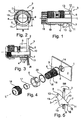
- the figures show a plug-in device for mounting in a passage opening 1 of a flat component 2, which is to be represented here by a section of a control cabinet wall.
- the plug-in device comprises a head part 3 for passing through the passage opening 1, a threaded part 4 to stay in front of the passage opening 1 and a screwed onto the threaded part 4 fastening nut 5 for fixing the plug-in device in the edge region of the passage opening 1.
- the threaded part 4 comprises not only the thread but also the area extending to the head part 3, which in the assembled state remains in front of the flat part 2 and does not carry any thread.
- the head part 3 has two opposing abutment regions 6, 7 projecting radially from the head part 3.
- the maximum distance A of the abutment regions 6, 7 is greater than the cross-sectional dimension Q of the here circular passage opening 1.
- two opposite, arranged between the abutment regions 6, 7 sections 8, 9 are provided, the maximum distance B is smaller than the cross-sectional dimension Q. the passage opening 1.
- the Fig. 2 clearly shows that the abutment regions 6, 7 and arranged between the abutment regions 6, 7 sections 8, 9 are arranged perpendicular to each other and formed in the sense of a double hook.
- the abutment areas 6, 7 are formed by the end face 10 of the head part 3 and each have a conical outer surface 11 converging away from the plug-in device. Furthermore, the abutment regions 6, 7 are each provided with a support surface 12 and a centering surface 13.
- the support surface 12 extends perpendicular to the longitudinal axis L of the plug-in device.
- Fig. 3 It is shown that the support surface 12 is supported in the assembled state against the rear edge region of the passage opening 1 of the sheet-like member 2.
- the centering surface 13 extends parallel to the longitudinal axis L and sets in the mounted state on the inner surface 14 of the passage opening 1 at.
- the support surfaces 12 and the centering surfaces 13 have a higher roughness than the flat component. 2
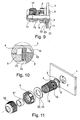
- FIGS. 4 . 6 and 11 illustrate that the arranged between the abutment portions 6, 7 sections 8, 9 have a flat outer surface. Both Fig. 4 and 6 the flat outer surface extends to the threaded part 4th
- the abutment areas 6, 7 different dimensions and shapes.
- the head part 3 in the assembled state defines an upper side, which is formed by the abutment region 6 and a lower side, which is formed by the abutment region 7.
- the upper abutment region 6 in the assembled state protrudes less strongly from the head part 3 than the lower abutment region 7 in the assembled state, which in FIG Fig. 2 to clarify the different geometry data is completed as a dashed line to a circle and where with D the difference of Dimension is designated. It is therefore an asymmetry of the abutment regions 6 and 7 intended with regard to the assembly and the load absorption.
- the lower abutment region 7 in the mounted state has a guide surface 15 converging from the centering surface 13 in the direction of the threaded part 4.
- the guide surface 15 contributes to the fact that the head part 3, when the fastening nut 5 is tightened to fix the first loose fit in the passage opening 1 plug-in device, gets into the correct position and the centering surfaces 13 and the support surfaces 12 can exert their effect.
- the mounting nut can also be equipped with an O-ring groove into which the O-ring is inserted.
- FIGS. 1 to 5 show that the plug-in device according to the first embodiment is part of a cable gland, consisting of cap nut 16, seal 17, lamellar basket 18, nozzle 19 is.
- the slat basket 18 is molded onto the nozzle 19 and the seal 17 is inserted into the slat basket 18.
- FIGS. 6 and 7 show the second embodiment, according to which the plug-in device is designed as a closure.
- the end face of the threaded part 4 is formed as a hexagon socket, which serves to receive a tool, in particular a hexagonal wrench.
- the head part 3 is closed here.
- the plug-in device according to the invention is formed as in the first embodiment in one piece with the cable gland. However, here was no cap nut 16, but a nut with Biegetik 21 screwed onto the cable gland.
- Fig. 9 to 11 show a fourth,sbesipiel the plug-in device according to the invention, wherein a sealing means 22 is provided in the form of an elastomeric ring, which contacts both the fastening nut 5 and the planar component 2, as well as the area between the threaded part 4 and the head part 3 in the operating position.
- the sealing means 22 has on its side facing the fastening nut 5 side a friction-reducing component 23, which is present here in the form of a Teflon coating.
- the sealing means 22 and the region between the threaded part 4 and the head part 3 are coordinated with one another such that a complete, dense contact surface can be formed.
- the aforementioned portion is cylindrical and has an outer cross section corresponding to the inner cross section of the sealant 22.
- the screwed onto the threaded part 4 fastening nut 5 for the plug-in device has a left-hand thread.
- the cap nut 16 and the nut with bending protection 21 for the cable gland are provided with a right-hand thread.
- sealing means 22 with the friction-reducing component 23 also play a role in plug-in devices in the form of closures or with bending protection parts or as the best part of a measuring device, in particular a float switch.
Landscapes
- Engineering & Computer Science (AREA)
- General Engineering & Computer Science (AREA)
- Architecture (AREA)
- Civil Engineering (AREA)
- Structural Engineering (AREA)
- Mechanical Engineering (AREA)
- Connector Housings Or Holding Contact Members (AREA)
- Installation Of Indoor Wiring (AREA)
- Dowels (AREA)
Claims (16)
- Dispositif enfichable à des fins de montage dans une ouverture traversante (1) d'un composant plat (2), notamment d'une paroi d'armoire de commande, comportant une partie de tête (3) pour traverser l'ouverture traversante (1), comportant une partie de filetage (4) pour rester dans l'ouverture traversante (1), comportant un écrou de fixation (5) vissable sur la partie de filetage (4) pour immobiliser le dispositif enfichable dans la zone de bord de l'ouverture traversante (1), dans lequel la partie de tête (3) présente des zones de contre-butée (6, 7) essentiellement en vis-à-vis, faisant saillie radialement depuis la partie de tête (3), dont l'espacement (A) maximal est plus grand que la dimension de section transversale (Q) de l'ouverture traversante (1),
caractérisé en ce que
des portions (8, 9) disposées entre les zones de contre-butée (6, 7) sont prévues, dont l'espacement maximal (B) est plus petit que la dimension de section transversale (Q) de l'ouverture traversante (1) et en ce que un moyen d'étanchéité (22) est prévu, qui contacte dans la position opérationnelle tant l'écrou de fixation (5) que le composant plat (2), ainsi que la zone entre la partie de filetage (4) et la partie de tête (3). - Dispositif enfichable selon la revendication 1, caractérisé en ce que la partie de tête (3) dans la position inclinée peut être guidée à travers l'ouverture traversante (1).
- Dispositif enfichable selon les revendications 1 ou 2, caractérisé en ce que les zones de contre-butée (6, 7) et les portions (8, 9) disposées entre les zones de contre-butée (6, 7) sont disposées perpendiculairement les unes aux autres.
- Dispositif enfichable selon une des revendications 1 à 3, caractérisé en ce que les zones de contre-butée (6, 7) sont conçues à la manière d'un double crochet.
- Dispositif enfichable selon une des revendications 1 à 4, caractérisé en ce que les zones de contre-butée (6, 7) sont réalisées par le côté frontal (10) de la partie de tête (3).
- Dispositif enfichable selon une des revendications 1 à 5, caractérisé en ce que les zones de contre-butée (6, 7) présentent respectivement une surface extérieure (11) conique convergente en s'écartant du dispositif enfichable.
- Dispositif enfichable selon une des revendications 1 à 6, caractérisé en ce que les zones de contre-butée (6, 7) présentent respectivement une surface d'appui (12), qui s'étend perpendiculairement à l'axe longitudinal (L) du dispositif enfichable et s'appuie en l'état monté contre la zone de bord du côté dorsale de l'ouverture traversante (1)
- Dispositif enfichable selon une des revendications 1 à 7, caractérisé en ce que les zones de contre-butée (6, 7) présentent chacune une surface de centrage (13), qui s'étend parallèlement à l'axe longitudinal (L) et vient reposer en l'état monté sur la surface intérieure (14) de l'ouverture traversante (1).
- Dispositif enfichable selon les revendications 7 ou 8, caractérisé en ce que la surface d'appui (12) et/ou la surface de centrage (13) présente une plus grande rugosité que le composant plat (2).
- Dispositif enfichable selon une des revendications 1 à 9, caractérisé en ce que les portions (8, 9) disposées entre les zones de contre-butée (6, 7) présentent une surface extérieure plane.
- Dispositif enfichable selon une des revendications 1 à 10, caractérisé en ce que la partie de tête (3) en l'état monté forme un côté supérieur et un côté inférieur, en ce que la zone de contre-butée (6) est disposée sur le côté supérieur et la zone de contre-butée (7) est disposée sur le côté inférieur et en ce que en l'état monté la zone de contre-butée supérieure (6) dépasse en saillie moins fortement de la partie de tête (3) que la zone de contre-butée inférieure (7) en l'état monté.
- Dispositif enfichable selon la revendication 13, caractérisé en ce que en l'état monté la zone de contre-butée inférieure (7) présente une surface de guidage (15) convergente depuis la surface de centrage (13) dans la direction de la partie de filetage (4).
- Dispositif enfichable selon une des revendications 1 à 12, caractérisé en ce que le dispositif enfichable est partie intégrante d'un vissage de câble ou que le dispositif enfichable est conçu comme une obturation.
- Dispositif enfichable selon une des revendications 1 à 13, caractérisé en ce que l'écrou de fixation (5) vissable sur la partie de filetage (4) présente un filetage gauche.
- Dispositif enfichable selon une des revendications 1 à 17, caractérisé en ce que le moyen d'étanchéité (22) présente sur son côté tourné vers l'écrou de fixation (5) un composant (23) réducteur de friction, notamment sous forme d'un revêtement.
- Dispositif enfichable selon une des revendications 1 à 15, caractérisé en ce que le moyen d'étanchéité (22) et la zone entre la partie de filetage (4) et la partie de tête (3) sont harmonisés l'un à l'autre, de telle sorte qu'une surface de contact étanche sans vide puisse être réalisée.
Applications Claiming Priority (2)
| Application Number | Priority Date | Filing Date | Title |
|---|---|---|---|
| DE200820001842 DE202008001842U1 (de) | 2008-02-09 | 2008-02-09 | Steckvorrichtung |
| PCT/DE2009/000163 WO2009097842A1 (fr) | 2008-02-09 | 2009-02-08 | Dispositif à enfichage |
Publications (2)
| Publication Number | Publication Date |
|---|---|
| EP2240987A1 EP2240987A1 (fr) | 2010-10-20 |
| EP2240987B1 true EP2240987B1 (fr) | 2013-12-04 |
Family
ID=39278224
Family Applications (1)
| Application Number | Title | Priority Date | Filing Date |
|---|---|---|---|
| EP09707611.1A Active EP2240987B1 (fr) | 2008-02-09 | 2009-02-08 | Dispositif a enfichage |
Country Status (3)
| Country | Link |
|---|---|
| EP (1) | EP2240987B1 (fr) |
| DE (2) | DE202008001842U1 (fr) |
| WO (1) | WO2009097842A1 (fr) |
Cited By (3)
| Publication number | Priority date | Publication date | Assignee | Title |
|---|---|---|---|---|
| DE202023101826U1 (de) | 2023-04-12 | 2024-07-15 | Obo Bettermann Hungary Kft | Langgutdurchführung sowie Anordnung umfassend eine solche Langgutdurchführung und eine Installationsdose |
| EP4546582A1 (fr) * | 2023-10-24 | 2025-04-30 | CENA Kunststoff GmbH | Traversée de câble |
| EP4614744A1 (fr) | 2024-03-06 | 2025-09-10 | OBO Bettermann Hungary Kft. | Traversée pour marchandises longues ainsi qu'agencement comprenant une telle traversée pour marchandises longues |
Families Citing this family (8)
| Publication number | Priority date | Publication date | Assignee | Title |
|---|---|---|---|---|
| ITMI20110290A1 (it) * | 2011-02-28 | 2012-08-29 | Gewiss Spa | Dispositivo pressacavo |
| DE102011018882A1 (de) | 2011-04-28 | 2012-10-31 | Jacob Gmbh Elektrotechnische Fabrik | Kabelverschraubung |
| DE202013002485U1 (de) * | 2013-03-15 | 2013-05-15 | Adam Gerich | Befestigungsvorrichtung für Kabelanschlüsse |
| DE102013223942A1 (de) * | 2013-11-22 | 2015-05-28 | Lq Mechatronik-Systeme Gmbh | Elektrisches Steckverbindungsteil |
| CN106099509A (zh) * | 2016-07-29 | 2016-11-09 | 国家电网公司 | 供电用光纤电源插座 |
| NL2019583B1 (en) * | 2017-09-20 | 2019-03-28 | Beele Eng Bv | System and method for providing a conduit sealingly to a through-opening in a plate-shaped construction element |
| EP4358371A1 (fr) * | 2022-10-17 | 2024-04-24 | Abb Schweiz Ag | Ensemble moteur électrique |
| EP4358329A1 (fr) * | 2022-10-17 | 2024-04-24 | Abb Schweiz Ag | Presse-étoupe de câble |
Family Cites Families (4)
| Publication number | Priority date | Publication date | Assignee | Title |
|---|---|---|---|---|
| DE19515860C2 (de) | 1995-04-29 | 2000-08-31 | Adam Gerich | Befestigungsvorrichtung für Bauteile, insbesondere für Schlauch-, Rohranschlüsse oder dergleichen |
| DE202004005839U1 (de) | 2004-04-14 | 2005-08-18 | Wiska Hoppmann & Mulsow Gmbh | Kabeleinführung |
| DE102005017690A1 (de) | 2005-04-08 | 2006-10-12 | Lapp Engineering & Co. | Kabeldurchführung |
| US7078623B1 (en) | 2005-11-30 | 2006-07-18 | Sheehan Robert K | Electrical conduit to junction box connection system |
-
2008
- 2008-02-09 DE DE200820001842 patent/DE202008001842U1/de not_active Expired - Lifetime
-
2009
- 2009-02-08 EP EP09707611.1A patent/EP2240987B1/fr active Active
- 2009-02-08 WO PCT/DE2009/000163 patent/WO2009097842A1/fr not_active Ceased
- 2009-02-08 DE DE112009000863T patent/DE112009000863A5/de not_active Withdrawn
Cited By (4)
| Publication number | Priority date | Publication date | Assignee | Title |
|---|---|---|---|---|
| DE202023101826U1 (de) | 2023-04-12 | 2024-07-15 | Obo Bettermann Hungary Kft | Langgutdurchführung sowie Anordnung umfassend eine solche Langgutdurchführung und eine Installationsdose |
| EP4447241A1 (fr) | 2023-04-12 | 2024-10-16 | OBO Bettermann Hungary Kft. | Traversée de marchandises longues ainsi qu'agencement comprenant une telle traversée de marchandises longues et une boîte d'installation |
| EP4546582A1 (fr) * | 2023-10-24 | 2025-04-30 | CENA Kunststoff GmbH | Traversée de câble |
| EP4614744A1 (fr) | 2024-03-06 | 2025-09-10 | OBO Bettermann Hungary Kft. | Traversée pour marchandises longues ainsi qu'agencement comprenant une telle traversée pour marchandises longues |
Also Published As
| Publication number | Publication date |
|---|---|
| DE202008001842U1 (de) | 2008-04-10 |
| EP2240987A1 (fr) | 2010-10-20 |
| WO2009097842A9 (fr) | 2010-04-01 |
| WO2009097842A1 (fr) | 2009-08-13 |
| DE112009000863A5 (de) | 2011-01-13 |
Similar Documents
| Publication | Publication Date | Title |
|---|---|---|
| WO2009097842A1 (fr) | Dispositif à enfichage | |
| DE68903541T2 (de) | Stossbefestiger. | |
| DE4137286C2 (de) | Ölfilter- oder Kraftstoffilter-Gehäuse | |
| DE4033763C2 (de) | Vorrichtung zum Sichern einer in einer Öffnung in einer Verkleidung aufgenommenen Mutter | |
| DE102008017423B4 (de) | Überspannungsschutzgerät | |
| EP2443352B1 (fr) | Système de liaison de barres profilées | |
| DE102007058051B3 (de) | Anordnung zur Schraubensicherung von elektrischen Anschlussklemmen | |
| WO2018210892A1 (fr) | Passage de câble | |
| EP3649353A1 (fr) | Système de fixation | |
| EP3132146B1 (fr) | Dispositif de fixation | |
| EP1903223B1 (fr) | Ecrou plastique | |
| EP0838984A2 (fr) | Baie électronique | |
| DE112008001364B4 (de) | Verbinder für Fluiddruckvorrichtungen | |
| EP3557084A1 (fr) | Élément de raccordement permettant de raccorder des éléments profilés | |
| EP2304250B1 (fr) | Clip à vis | |
| EP0442367A2 (fr) | Dispositif pour boucher une ouverture de traversée de câble dans une armoire de commutation | |
| EP3181919B1 (fr) | Élément de retenue d'installation comprenant une pluralité d'éléments de fermeture | |
| DE20312075U1 (de) | Vorrichtung mit zwei durch eine Verbindungsschraube zusammengehaltenen Hohlprofilen sowie Werkzeug dazu | |
| DE2930833C3 (de) | Klemmuffe | |
| DE4413782A1 (de) | Schraube | |
| DE29603389U1 (de) | Schnellverschluß | |
| DE102011109451A1 (de) | Vorrichtung zur Halterung eines Gewindestifts | |
| DE202008015523U1 (de) | Verschraubung | |
| EP3828426A1 (fr) | Élément de fixation pour tubes à plusieurs bordures | |
| DE20104604U1 (de) | Befestigungselement sowie Gestell oder Schrank mit einem Befestigungselement |
Legal Events
| Date | Code | Title | Description |
|---|---|---|---|
| PUAI | Public reference made under article 153(3) epc to a published international application that has entered the european phase |
Free format text: ORIGINAL CODE: 0009012 |
|
| 17P | Request for examination filed |
Effective date: 20100628 |
|
| AK | Designated contracting states |
Kind code of ref document: A1 Designated state(s): AT BE BG CH CY CZ DE DK EE ES FI FR GB GR HR HU IE IS IT LI LT LU LV MC MK MT NL NO PL PT RO SE SI SK TR |
|
| AX | Request for extension of the european patent |
Extension state: AL BA RS |
|
| DAX | Request for extension of the european patent (deleted) | ||
| 17Q | First examination report despatched |
Effective date: 20110626 |
|
| GRAP | Despatch of communication of intention to grant a patent |
Free format text: ORIGINAL CODE: EPIDOSNIGR1 |
|
| RIC1 | Information provided on ipc code assigned before grant |
Ipc: H02G 3/06 20060101AFI20130708BHEP Ipc: H01R 13/59 20060101ALI20130708BHEP Ipc: H01R 13/52 20060101ALI20130708BHEP Ipc: H01R 13/56 20060101ALI20130708BHEP Ipc: H01R 13/443 20060101ALI20130708BHEP Ipc: H01R 13/74 20060101ALI20130708BHEP Ipc: F16L 5/06 20060101ALI20130708BHEP |
|
| INTG | Intention to grant announced |
Effective date: 20130806 |
|
| GRAS | Grant fee paid |
Free format text: ORIGINAL CODE: EPIDOSNIGR3 |
|
| GRAA | (expected) grant |
Free format text: ORIGINAL CODE: 0009210 |
|
| AK | Designated contracting states |
Kind code of ref document: B1 Designated state(s): AT BE BG CH CY CZ DE DK EE ES FI FR GB GR HR HU IE IS IT LI LT LU LV MC MK MT NL NO PL PT RO SE SI SK TR |
|
| REG | Reference to a national code |
Ref country code: GB Ref legal event code: FG4D Free format text: NOT ENGLISH |
|
| REG | Reference to a national code |
Ref country code: CH Ref legal event code: EP |
|
| REG | Reference to a national code |
Ref country code: AT Ref legal event code: REF Ref document number: 643860 Country of ref document: AT Kind code of ref document: T Effective date: 20140115 Ref country code: IE Ref legal event code: FG4D Free format text: LANGUAGE OF EP DOCUMENT: GERMAN |
|
| REG | Reference to a national code |
Ref country code: DE Ref legal event code: R096 Ref document number: 502009008452 Country of ref document: DE Effective date: 20140130 |
|
| REG | Reference to a national code |
Ref country code: NL Ref legal event code: VDEP Effective date: 20131204 |
|
| PG25 | Lapsed in a contracting state [announced via postgrant information from national office to epo] |
Ref country code: NL Free format text: LAPSE BECAUSE OF FAILURE TO SUBMIT A TRANSLATION OF THE DESCRIPTION OR TO PAY THE FEE WITHIN THE PRESCRIBED TIME-LIMIT Effective date: 20131204 Ref country code: SE Free format text: LAPSE BECAUSE OF FAILURE TO SUBMIT A TRANSLATION OF THE DESCRIPTION OR TO PAY THE FEE WITHIN THE PRESCRIBED TIME-LIMIT Effective date: 20131204 Ref country code: NO Free format text: LAPSE BECAUSE OF FAILURE TO SUBMIT A TRANSLATION OF THE DESCRIPTION OR TO PAY THE FEE WITHIN THE PRESCRIBED TIME-LIMIT Effective date: 20140304 Ref country code: FI Free format text: LAPSE BECAUSE OF FAILURE TO SUBMIT A TRANSLATION OF THE DESCRIPTION OR TO PAY THE FEE WITHIN THE PRESCRIBED TIME-LIMIT Effective date: 20131204 Ref country code: LT Free format text: LAPSE BECAUSE OF FAILURE TO SUBMIT A TRANSLATION OF THE DESCRIPTION OR TO PAY THE FEE WITHIN THE PRESCRIBED TIME-LIMIT Effective date: 20131204 Ref country code: HR Free format text: LAPSE BECAUSE OF FAILURE TO SUBMIT A TRANSLATION OF THE DESCRIPTION OR TO PAY THE FEE WITHIN THE PRESCRIBED TIME-LIMIT Effective date: 20131204 |
|
| REG | Reference to a national code |
Ref country code: LT Ref legal event code: MG4D |
|
| PG25 | Lapsed in a contracting state [announced via postgrant information from national office to epo] |
Ref country code: CY Free format text: LAPSE BECAUSE OF FAILURE TO SUBMIT A TRANSLATION OF THE DESCRIPTION OR TO PAY THE FEE WITHIN THE PRESCRIBED TIME-LIMIT Effective date: 20131204 Ref country code: LV Free format text: LAPSE BECAUSE OF FAILURE TO SUBMIT A TRANSLATION OF THE DESCRIPTION OR TO PAY THE FEE WITHIN THE PRESCRIBED TIME-LIMIT Effective date: 20131204 |
|
| PG25 | Lapsed in a contracting state [announced via postgrant information from national office to epo] |
Ref country code: EE Free format text: LAPSE BECAUSE OF FAILURE TO SUBMIT A TRANSLATION OF THE DESCRIPTION OR TO PAY THE FEE WITHIN THE PRESCRIBED TIME-LIMIT Effective date: 20131204 Ref country code: IS Free format text: LAPSE BECAUSE OF FAILURE TO SUBMIT A TRANSLATION OF THE DESCRIPTION OR TO PAY THE FEE WITHIN THE PRESCRIBED TIME-LIMIT Effective date: 20140404 |
|
| PG25 | Lapsed in a contracting state [announced via postgrant information from national office to epo] |
Ref country code: PL Free format text: LAPSE BECAUSE OF FAILURE TO SUBMIT A TRANSLATION OF THE DESCRIPTION OR TO PAY THE FEE WITHIN THE PRESCRIBED TIME-LIMIT Effective date: 20131204 Ref country code: PT Free format text: LAPSE BECAUSE OF FAILURE TO SUBMIT A TRANSLATION OF THE DESCRIPTION OR TO PAY THE FEE WITHIN THE PRESCRIBED TIME-LIMIT Effective date: 20140404 Ref country code: CZ Free format text: LAPSE BECAUSE OF FAILURE TO SUBMIT A TRANSLATION OF THE DESCRIPTION OR TO PAY THE FEE WITHIN THE PRESCRIBED TIME-LIMIT Effective date: 20131204 Ref country code: ES Free format text: LAPSE BECAUSE OF FAILURE TO SUBMIT A TRANSLATION OF THE DESCRIPTION OR TO PAY THE FEE WITHIN THE PRESCRIBED TIME-LIMIT Effective date: 20131204 Ref country code: RO Free format text: LAPSE BECAUSE OF FAILURE TO SUBMIT A TRANSLATION OF THE DESCRIPTION OR TO PAY THE FEE WITHIN THE PRESCRIBED TIME-LIMIT Effective date: 20131204 Ref country code: SK Free format text: LAPSE BECAUSE OF FAILURE TO SUBMIT A TRANSLATION OF THE DESCRIPTION OR TO PAY THE FEE WITHIN THE PRESCRIBED TIME-LIMIT Effective date: 20131204 |
|
| BERE | Be: lapsed |
Owner name: JACOB G.M.B.H. ELEKTROTECHNISCHE FABRIK Effective date: 20140228 |
|
| REG | Reference to a national code |
Ref country code: DE Ref legal event code: R097 Ref document number: 502009008452 Country of ref document: DE |
|
| PG25 | Lapsed in a contracting state [announced via postgrant information from national office to epo] |
Ref country code: LU Free format text: LAPSE BECAUSE OF FAILURE TO SUBMIT A TRANSLATION OF THE DESCRIPTION OR TO PAY THE FEE WITHIN THE PRESCRIBED TIME-LIMIT Effective date: 20140208 Ref country code: MC Free format text: LAPSE BECAUSE OF FAILURE TO SUBMIT A TRANSLATION OF THE DESCRIPTION OR TO PAY THE FEE WITHIN THE PRESCRIBED TIME-LIMIT Effective date: 20131204 |
|
| REG | Reference to a national code |
Ref country code: CH Ref legal event code: PL |
|
| PLBE | No opposition filed within time limit |
Free format text: ORIGINAL CODE: 0009261 |
|
| STAA | Information on the status of an ep patent application or granted ep patent |
Free format text: STATUS: NO OPPOSITION FILED WITHIN TIME LIMIT |
|
| PG25 | Lapsed in a contracting state [announced via postgrant information from national office to epo] |
Ref country code: LI Free format text: LAPSE BECAUSE OF NON-PAYMENT OF DUE FEES Effective date: 20140228 Ref country code: DK Free format text: LAPSE BECAUSE OF FAILURE TO SUBMIT A TRANSLATION OF THE DESCRIPTION OR TO PAY THE FEE WITHIN THE PRESCRIBED TIME-LIMIT Effective date: 20131204 Ref country code: CH Free format text: LAPSE BECAUSE OF NON-PAYMENT OF DUE FEES Effective date: 20140228 |
|
| 26N | No opposition filed |
Effective date: 20140905 |
|
| REG | Reference to a national code |
Ref country code: FR Ref legal event code: ST Effective date: 20141031 |
|
| GBPC | Gb: european patent ceased through non-payment of renewal fee |
Effective date: 20140304 |
|
| REG | Reference to a national code |
Ref country code: IE Ref legal event code: MM4A |
|
| REG | Reference to a national code |
Ref country code: DE Ref legal event code: R097 Ref document number: 502009008452 Country of ref document: DE Effective date: 20140905 |
|
| PG25 | Lapsed in a contracting state [announced via postgrant information from national office to epo] |
Ref country code: FR Free format text: LAPSE BECAUSE OF NON-PAYMENT OF DUE FEES Effective date: 20140228 Ref country code: IE Free format text: LAPSE BECAUSE OF NON-PAYMENT OF DUE FEES Effective date: 20140208 Ref country code: GB Free format text: LAPSE BECAUSE OF NON-PAYMENT OF DUE FEES Effective date: 20140304 Ref country code: BE Free format text: LAPSE BECAUSE OF NON-PAYMENT OF DUE FEES Effective date: 20140228 |
|
| PG25 | Lapsed in a contracting state [announced via postgrant information from national office to epo] |
Ref country code: SI Free format text: LAPSE BECAUSE OF FAILURE TO SUBMIT A TRANSLATION OF THE DESCRIPTION OR TO PAY THE FEE WITHIN THE PRESCRIBED TIME-LIMIT Effective date: 20131204 |
|
| PG25 | Lapsed in a contracting state [announced via postgrant information from national office to epo] |
Ref country code: IT Free format text: LAPSE BECAUSE OF FAILURE TO SUBMIT A TRANSLATION OF THE DESCRIPTION OR TO PAY THE FEE WITHIN THE PRESCRIBED TIME-LIMIT Effective date: 20131204 |
|
| REG | Reference to a national code |
Ref country code: AT Ref legal event code: MM01 Ref document number: 643860 Country of ref document: AT Kind code of ref document: T Effective date: 20140208 |
|
| PG25 | Lapsed in a contracting state [announced via postgrant information from national office to epo] |
Ref country code: AT Free format text: LAPSE BECAUSE OF NON-PAYMENT OF DUE FEES Effective date: 20140208 |
|
| PG25 | Lapsed in a contracting state [announced via postgrant information from national office to epo] |
Ref country code: MT Free format text: LAPSE BECAUSE OF FAILURE TO SUBMIT A TRANSLATION OF THE DESCRIPTION OR TO PAY THE FEE WITHIN THE PRESCRIBED TIME-LIMIT Effective date: 20131204 |
|
| PG25 | Lapsed in a contracting state [announced via postgrant information from national office to epo] |
Ref country code: BG Free format text: LAPSE BECAUSE OF FAILURE TO SUBMIT A TRANSLATION OF THE DESCRIPTION OR TO PAY THE FEE WITHIN THE PRESCRIBED TIME-LIMIT Effective date: 20131204 |
|
| PG25 | Lapsed in a contracting state [announced via postgrant information from national office to epo] |
Ref country code: GR Free format text: LAPSE BECAUSE OF FAILURE TO SUBMIT A TRANSLATION OF THE DESCRIPTION OR TO PAY THE FEE WITHIN THE PRESCRIBED TIME-LIMIT Effective date: 20140305 |
|
| PG25 | Lapsed in a contracting state [announced via postgrant information from national office to epo] |
Ref country code: HU Free format text: LAPSE BECAUSE OF FAILURE TO SUBMIT A TRANSLATION OF THE DESCRIPTION OR TO PAY THE FEE WITHIN THE PRESCRIBED TIME-LIMIT; INVALID AB INITIO Effective date: 20090208 Ref country code: TR Free format text: LAPSE BECAUSE OF FAILURE TO SUBMIT A TRANSLATION OF THE DESCRIPTION OR TO PAY THE FEE WITHIN THE PRESCRIBED TIME-LIMIT Effective date: 20131204 |
|
| PG25 | Lapsed in a contracting state [announced via postgrant information from national office to epo] |
Ref country code: MK Free format text: LAPSE BECAUSE OF FAILURE TO SUBMIT A TRANSLATION OF THE DESCRIPTION OR TO PAY THE FEE WITHIN THE PRESCRIBED TIME-LIMIT Effective date: 20131204 |
|
| PGFP | Annual fee paid to national office [announced via postgrant information from national office to epo] |
Ref country code: DE Payment date: 20260119 Year of fee payment: 18 |