EP2241061B1 - Réseau de pompes cryostatiques - Google Patents
Réseau de pompes cryostatiques Download PDFInfo
- Publication number
- EP2241061B1 EP2241061B1 EP09704663.5A EP09704663A EP2241061B1 EP 2241061 B1 EP2241061 B1 EP 2241061B1 EP 09704663 A EP09704663 A EP 09704663A EP 2241061 B1 EP2241061 B1 EP 2241061B1
- Authority
- EP
- European Patent Office
- Prior art keywords
- network
- node
- nodes
- processes
- vacuum
- Prior art date
- Legal status (The legal status is an assumption and is not a legal conclusion. Google has not performed a legal analysis and makes no representation as to the accuracy of the status listed.)
- Active
Links
- 238000000034 method Methods 0.000 claims description 101
- 238000004891 communication Methods 0.000 claims description 50
- 239000001307 helium Substances 0.000 claims description 14
- 229910052734 helium Inorganic materials 0.000 claims description 14
- SWQJXJOGLNCZEY-UHFFFAOYSA-N helium atom Chemical compound [He] SWQJXJOGLNCZEY-UHFFFAOYSA-N 0.000 claims description 14
- 230000008929 regeneration Effects 0.000 claims description 13
- 238000011069 regeneration method Methods 0.000 claims description 13
- 238000012544 monitoring process Methods 0.000 claims description 9
- 238000010926 purge Methods 0.000 claims description 3
- 238000013480 data collection Methods 0.000 claims description 2
- 230000008676 import Effects 0.000 claims 1
- 238000010586 diagram Methods 0.000 description 17
- 238000002955 isolation Methods 0.000 description 3
- 238000013507 mapping Methods 0.000 description 3
- 238000012545 processing Methods 0.000 description 3
- 230000000644 propagated effect Effects 0.000 description 3
- 230000005540 biological transmission Effects 0.000 description 2
- 238000001514 detection method Methods 0.000 description 2
- 238000009826 distribution Methods 0.000 description 2
- 238000004519 manufacturing process Methods 0.000 description 2
- 238000011084 recovery Methods 0.000 description 2
- 230000002123 temporal effect Effects 0.000 description 2
- 238000000137 annealing Methods 0.000 description 1
- 238000012864 cross contamination Methods 0.000 description 1
- 238000007872 degassing Methods 0.000 description 1
- 230000001419 dependent effect Effects 0.000 description 1
- 238000005530 etching Methods 0.000 description 1
- 239000007789 gas Substances 0.000 description 1
- 230000000977 initiatory effect Effects 0.000 description 1
- 230000006855 networking Effects 0.000 description 1
- 230000003647 oxidation Effects 0.000 description 1
- 238000007254 oxidation reaction Methods 0.000 description 1
- 230000000737 periodic effect Effects 0.000 description 1
- 239000003507 refrigerant Substances 0.000 description 1
- 239000004065 semiconductor Substances 0.000 description 1
- 238000005245 sintering Methods 0.000 description 1
- 238000001179 sorption measurement Methods 0.000 description 1
- 239000000126 substance Substances 0.000 description 1
- 230000026676 system process Effects 0.000 description 1
- 238000012546 transfer Methods 0.000 description 1
- 238000007740 vapor deposition Methods 0.000 description 1
- XLYOFNOQVPJJNP-UHFFFAOYSA-N water Substances O XLYOFNOQVPJJNP-UHFFFAOYSA-N 0.000 description 1
Images


Classifications
-
- F—MECHANICAL ENGINEERING; LIGHTING; HEATING; WEAPONS; BLASTING
- F04—POSITIVE - DISPLACEMENT MACHINES FOR LIQUIDS; PUMPS FOR LIQUIDS OR ELASTIC FLUIDS
- F04B—POSITIVE-DISPLACEMENT MACHINES FOR LIQUIDS; PUMPS
- F04B37/00—Pumps having pertinent characteristics not provided for in, or of interest apart from, groups F04B25/00 - F04B35/00
- F04B37/06—Pumps having pertinent characteristics not provided for in, or of interest apart from, groups F04B25/00 - F04B35/00 for evacuating by thermal means
- F04B37/08—Pumps having pertinent characteristics not provided for in, or of interest apart from, groups F04B25/00 - F04B35/00 for evacuating by thermal means by condensing or freezing, e.g. cryogenic pumps
-
- H—ELECTRICITY
- H04—ELECTRIC COMMUNICATION TECHNIQUE
- H04L—TRANSMISSION OF DIGITAL INFORMATION, e.g. TELEGRAPHIC COMMUNICATION
- H04L12/00—Data switching networks
- H04L12/28—Data switching networks characterised by path configuration, e.g. LAN [Local Area Networks] or WAN [Wide Area Networks]
- H04L12/40—Bus networks
- H04L12/403—Bus networks with centralised control, e.g. polling
-
- F—MECHANICAL ENGINEERING; LIGHTING; HEATING; WEAPONS; BLASTING
- F04—POSITIVE - DISPLACEMENT MACHINES FOR LIQUIDS; PUMPS FOR LIQUIDS OR ELASTIC FLUIDS
- F04B—POSITIVE-DISPLACEMENT MACHINES FOR LIQUIDS; PUMPS
- F04B49/00—Control, e.g. of pump delivery, or pump pressure of, or safety measures for, machines, pumps, or pumping installations, not otherwise provided for, or of interest apart from, groups F04B1/00 - F04B47/00
-
- G—PHYSICS
- G05—CONTROLLING; REGULATING
- G05B—CONTROL OR REGULATING SYSTEMS IN GENERAL; FUNCTIONAL ELEMENTS OF SUCH SYSTEMS; MONITORING OR TESTING ARRANGEMENTS FOR SUCH SYSTEMS OR ELEMENTS
- G05B9/00—Safety arrangements
- G05B9/02—Safety arrangements electric
-
- Y—GENERAL TAGGING OF NEW TECHNOLOGICAL DEVELOPMENTS; GENERAL TAGGING OF CROSS-SECTIONAL TECHNOLOGIES SPANNING OVER SEVERAL SECTIONS OF THE IPC; TECHNICAL SUBJECTS COVERED BY FORMER USPC CROSS-REFERENCE ART COLLECTIONS [XRACs] AND DIGESTS
- Y10—TECHNICAL SUBJECTS COVERED BY FORMER USPC
- Y10S—TECHNICAL SUBJECTS COVERED BY FORMER USPC CROSS-REFERENCE ART COLLECTIONS [XRACs] AND DIGESTS
- Y10S417/00—Pumps
Definitions
- a cryogenic vacuum system typically includes at least one cryogenic vacuum pump (cryopump) and at least one compressor for supplying compressed helium to the cryopump.
- the system also often includes other components such as roughing pumps, waterpumps (a single stage cryopump), turbopumps, isolation valves and gauges. Together, these components operate to provide vacuum to a broader system, such as a cluster tool for semiconductor processing.
- a cluster tool includes a tool host controller providing top-level control over all systems within the cluster tool.
- the tool includes a series of processing chambers for performing various semiconductor-fabrication processes such as wafer etching, chemical or plasma vapor deposition, oxidation, sintering, degassing, wafer transfer, and annealing. These processes often are performed in separate chambers, each of which may include a cryopump of the cryogenic vacuum system.
- a conventional vacuum system typically includes a network interface terminal acts as an interface between the tool host controller and the network of cryopumps within the system.
- Other vacuum system components such as a roughing pump, compressor, gauges, waterpump, turbomolecular pump, and gate valve, are typically coupled with the tool host controller to allow the tool host controller to issue commands for controlling the operation of these components.
- US6233948 on which the pre-characterising portion of claim 1 is based, discloses a control apparatus for a plurality of cryopumps.
- EP0754991 discloses a fault tolerant distributed control system.
- a first aspect of the present invention provides a vacuum control network system, as defined in claim 1. Optional features are recited in the dependent claims.
- a second aspect of the present invention provides a method of managing a vacuum control system, as defined in claim 18.
- Network ring segments may be provided between node pairs to form a ring with the plurality of nodes, thereby enabling internode communication via the ring.
- a network controller located at one of the nodes or external to the nodes, may manage the network such that only a single path connects any two nodes and it also determines whether a fault has occurred at one of the ring segments or in one of the nodes. Based on a detected fault, network ring segments can be enabled and disabled to reconfigure the topology of the network, thereby enabling continued communications among all network nodes.
- network ring segments may be disabled and enabled independent of the integrity of that network connector, for example by disabling an uncompromised network ring segment connector.
- the physical network ring may form a virtual "bus."
- a previously disabled network ring segment may be enabled in order to carry communications following a fault at another network ring segment or node.
- Each of the nodes may be configured to monitor and detect errors in adjacent network ring segments and nodes, reporting the errors to a common node or network controller.
- At least one node may be communicatively coupled to a separate vacuum network controller to control vacuum pumps and other components via communications across the vacuum control network.
- a redundant signal path may be provided to connect an additional node to the vacuum network controller.
- one or more nodes of the network may include logic (or otherwise be configured) for initiating, controlling and managing operational processes of the vacuum control system, such as helium management, controlling safety interlocks and coordinating group regeneration for cryopumps and rough and purge control for turbomolecular pumps.
- Each of the nodes may therefore operate as a process master, controlling a set of operational processes among vacuum components locally and at other nodes of the network.
- Each process master node therefore, may assume control over a set of processes making up a share of the entirety of processes for operating and managing the vacuum control system.
- one or more nodes may be configured to coordinate operations at other nodes, for example by controlling or allocating helium supply to or from a node and controlling access to a vacuum manifold for regeneration for a cryopump node.
- a particular node may be configured to operate as the vacuum network manager, monitoring and controlling operation and configuration of the network.
- a single node may be selected as a "supemode" to control processes at the other nodes.
- the control responsibility is passed to another node on the network, being selected as a successive supernode.
- responsibility over a set of operational processes may be passed from a first process master node to a second process master node when the first process master node exhibits a fault or becomes unavailable.
- Another embodiment uses the passage of the vacuum network control from one node to another after fault of the controlling node in topologies that include Ethernet ring, star and bus configurations.
- An additional embodiment includes redundant connections between the component monitor server and nodes on the vacuum network for added fault tolerance.
- Another embodiment includes fault tolerance for a configuration where one or more of the vacuum components is located on one or more different hubs than the remainder of the vacuum components such as a compressor in a subfab. Fault tolerance is achieved through redundant connections for the other items to the different hubs and monitoring and control of the assignments of the communication segments to the hub by the vacuum network controller.
- Fig. 1 is a schematic diagram of a typical prior art vacuum system employing a vacuum pump network 18.
- Example vacuum systems employing such a network are provided in U.S. Patent No. 6,671,583 , entitled "Vacuum System Information Network”.
- a network interface terminal (NIT) 12 connects via the network 18 to one or more pumps in a cluster tool.
- the illustrative system of Fig. 1 comprises various pumps including a cryopump 20, a waterpump 22 and a turbo and water pump combination 24.
- the NIT 12 interfaces with a tool host controller 4 via an RS-232 connection 6.
- the NIT 12 can also connect to other systems such as a central control station 8 via a central control link 10 and to a service terminal 16 via a service link 14.
- the NIT 12 supports only vacuum components that have an appropriate network communications interface. Third-party sensors, which cannot be connected to the NIT 12, must be connected directly to the tool host controller 4, thus placing more burden on the tool host controller 4.
- Fig. 2 is a schematic diagram of a second vacuum system 30 as known in the art.
- a vacuum network controller (VNC) 34 takes the place of the NIT 12 of Fig. 1 .
- a VNC is described more fully in Patent No. 6,272,400 , entitled "Vacuum Network Controller”.
- the VNC 34 communicates with the tool host controller 4 over a tool communication link 32, which is not limited to just RS-232 as was the connection 6 of FIG. 1 .
- the VNC 34 uses a flexible communication interface 40, the VNC 34 communicates with a central control station 8 over any of a variety of protocols.
- the VNC 34 also interfaces with a fabrication facility network 36 and with a server 38.
- the VNC 34 communicates over a daisy-chained serial bus 42 such as a BitBus with a plurality of vacuum pumps 20, 22, 24, 44 and other components such as valves 46, gauges 48, rough pumps 50 and compressors 52.
- a daisy-chained serial bus 42 such as a BitBus
- valves 46, gauges 48, rough pumps 50 and compressors 52 A disadvantage of this system is that to insert a new component into the middle of the bus 42, connections between the bus and components must be broken. In addition, if one component or its connection is faulty all of the equipment ceases control central.
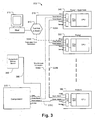
- Fig. 3 is a schematic diagram of a vacuum control network 300 for a vacuum control system.
- the network 300 comprises a number of nodes connected as an Ethernet "ring," including a first vacuum pump (“Pump 1") 340, a second vacuum pump (“Pump 2”) 350, a third vacuum pump (“Pump N”) 360, and a compressor 370.
- each of the vacuum pumps 340, 350, 360 may be a cryopump or a sorption or mechanical roughing pump, the compressor 370 providing a refrigerant (e.g., helium) to each of the cryopumps.
- a refrigerant e.g., helium
- a network host 310 operates as an overall host tool controller.
- the host 310 provides high level commands to the components at each of the nodes of network 300 in a distributed control configuration.
- the host 310 communicates with each node on the vacuum control network 300 to monitor and control components and processes at the vacuum pumps 340, 350, 360, compressor 370 and other equipment, such as a waterpump, turbomolecular pump, roughing pump, gauges or vacuum isolation valves, which may comprise additional nodes on the network 300. Communications between the host 310 and a first node of the network 300, Pump1 340, are made via a host network link 315.
- the network 300 may comprise an Ethernet physical layer utilizing Transmission Control Protocol and Internet Protocol (TCP/IP) to facilitate internode communications between the host 310, cryopumps 340, 350, 360, compressor 370 and other nodes on the network 300.
- TCP/IP Transmission Control Protocol and Internet Protocol
- each node includes an Ethernet switch, Ethernet Media Access Control (MAC) and other logic (i.e., central processing unit (CPU)), being a network communications interface, for enabling internode TCP/IP communications.
- MAC Ethernet Media Access Control
- CPU central processing unit
- the nodes of the network 300 are connected to enable an Ethernet ring topology: Pump1 340 connects to Pump2 350 via network link (hereinafter referred to as "ring segment") 335A; Pump2 350 connects to PumpN 360 (or one or more intermediary nodes, as illustrated by the dashed line) via network ring segment 335B; Pump N 360 connects to the compressor 370 via network ring segment 335C; and the compressor 370 connects to Pump1 340 via network ring segment 335D.
- These network ring segments 335A-D connect to one of two Ethernet ports ("Pump Network 1" and "Pump Network 2") at each node, effectively forming a "ring” connecting all of the nodes.
- Network link 335D is shown as a dotted line to illustrate a disabled redundant link, described further below with reference to Figs. 4a-b .
- a host 310 utilizes the ring topology of the network 300 to communicate with the vacuum pumps 340, 350, 360, the compressor 370, and other nodes on the network 300 to monitor and provide high level control processes of a vacuum pump system.
- the host 310 can communicate with vacuum network via Ethernet or the existing RS-232 method.
- the host may issue communications to initiate group regeneration, individual pump regeneration or helium management, reconfigure the nodes, or exercise isolation valve control at one or more vacuum pumps.
- such functionality for management and control referred to as "host functions,” may be distributed among the vacuum pumps 340, 350, 360 and compressor 370 as described below with reference to Fig. 7 .
- Each node may be assigned a local network address (e.g., an IP Address) by the host 310 or autonomously in coordination with the other nodes.
- the host 310 transmits network communications to the network hub 312 or other network access point, which routes those communications to Pump1 via the host network link 315.
- the network hub may 312 be omitted, the host 310 connected directly to Pump1 340 or other node.
- Communications may be routed via a redundant host connection 335E to Pump2 or another node, thereby providing a "backup" communications link in the event that host network link 315 or Pump1 becomes unavailable or disabled.
- Host communications are then routed between nodes in the Ethernet ring to arrive at the node(s) to which the communications are directed.
- each node monitors ingress and egress network traffic at its Ethernet ports, thereby providing information for configuring network traffic and fault detection.
- Example processes by which communications are monitored and propagated through the network 300, and particularly among network nodes comprising an Ethernet ring, are described in further detail below with reference to Figs. 5a-c and 6 .
- the compressor 370 may be configured to communicate with a component monitor server (CMS) 385 via an external network link 386.
- CMS component monitor server
- one or more of the nodes such as the vacuum pumps 340, 350, 360, compressor 370, and gauges provides data relating to its performance, configuration or other characteristics, which in turn indicate status of the vacuum pump system.
- This data is routed through one of the nodes, such as compressor 370 to the CMS 385, which collects this data for analysis of the vacuum pump system. Based on this analysis, operation of the vacuum pump system can be optimized or diagnosed for faults.
- An additional redundant link (not shown) from one of the other nodes to the CMS may be used to provide redundant communication to the CMS if the primary link fails.
- Fig. 4a is a block diagram of a vacuum control network 400, which may incorporate features of the network 300 described above with reference to Fig. 3 .
- Cryopump1 440, Cryopump2 450, vacuum pump3 460 and compressor 470 are connected via network ring segments 435A-D to form an Ethernet ring.
- the host 410 connects to Cryopump1 440 via host network link 415 for propagation of communications through the Ethernet ring.
- a redundant host network link 416 enables such communications in the event of a fault.
- Cryopump2 connects via an external network link 485 to a CMS 485. Alternatively, the CMS 485 or redundant host network link 416 may connect with other nodes in the network.
- Cryopump1 440 operates as a "supernode” or as a "process master” of the network 400, meaning that it performs additional functions to manage the vacuum network 400 and/or controls processes at the node components 450, 460 and 470.
- One or more of the nodes 440, 450, 460, 470 may be configured to have the capability of operating as a process master or as a supernode. In a supernode configuration, the host 410 designates a single one of the nodes as the supernode, or the nodes may arbitrate among themselves.
- Cryopump1 440 performs network management, controlling assignment of a disconnect at the network links 435A-D, and controls all or substantially all operational processes of the vacuum control system.
- plural nodes are selected as process master, where each node controls a respective set of processes.
- the respective sets of processes may be distinct from one another, thereby providing each process master with a different assignment of responsibilities, management and control.
- some or all of the nodes e.g., nodes 440, 450, 460, 470
- Cryopump1 440 may be selected as the process master with respect to network management processes. Providing that all network ring segments 435A-D are operable, upon initialization of the vacuum control network 400, Cryopump1 440 (as a process master or supernode) disables one network ring segment such as 435A by mapping a "virtual disconnect" to the network between the respective nodes (Cryopump1 440 and Cryopump2 450). In doing so, Cryopump1 440 indicates to itself and to Cryopump2 to refrain from transmitting any communications via network ring segment 435. As a result, the remaining network ring segments 435B-D form a network bus through which internode communication and communication with the host 410 is propagated.
- Fig. 4b is a block diagram of the vacuum control network 400 following a fault in a network ring segment.
- network ring segment 435B becomes disabled, which may be caused by a failure of the physical line connecting the nodes of the networking hardware (e.g., Ethernet switch) at a node or the equipment at the node is removed or completely inoperable.
- Cryopump1 caused network ring segment 435A to be disabled by mapping a virtual disconnect to the segment 435A, as shown in Fig. 4a .
- the previous disconnect mapped to network ring segment 435A in addition to the present fault at network ring segment 435B, prevents communication between Cryopump2 450 and other nodes of the network 400.
- Vacuum pump3 460 monitors network communications across network ring segments 435B-C, for example by detecting packet error or issuing a periodic ICMP "echo request" and listening for a corresponding "echo response" from other nodes. Vacuum pump3 460 thus detects the disconnect at network ring segment 435B and propagates an error report indicating the location of the disconnect to Cryopump1 440. Alternatively or in addition, Cryopump2 450 may detect the disconnect at network ring segment 435B and transmit a corresponding error report to Cryopump1 440 by enabling network ring segment 435A and transmitting the report across this segment 435A.
- embodiments of the invention may employ Spanning Tree Protocol, a communication protocol enabling Ethernet redundancy.
- Spanning tree protocol the root node at Cryopump1 440 transmits topology info to the various switches at nodes Cryopump2 450, vacuum pump3 460 and compressor 470 at a recurring interval (e.g., 2 seconds), and receives a reply indicating if each switch can verify this topology. If not, it makes the appropriate topology changes in its topology table and propagates these changes to the switches.
- Each of the switches is configured to reply to a received topology as defined under the Spanning Tree algorithm.
- Cryopump1 440 In response to the report transmitted by Cryopump2 450, Cryopump1 440 (as a process master or supernode) removes the virtual disconnect at network ring segment 435A and maps a disconnect to network ring segment 435B. In doing so, Cryopump1 440 enables network ring segment 435A by transmitting instructions to Cryopump2 450, via segment 435A, to propagate network packets through network ring segment 435A. Further, Cryopump1 transmits instructions to Cryopump2 450 and Vacuum pump3 460 to disable communications across network ring segment 435B. As a result, the network 400 is reconfigured to continue operation and communication between all nodes in response to a fault in the network 400. Processes at each node with respect to a fault event are described in further detail below with reference to Figs. 5a-c .
- Fig. 5a is a flow diagram illustrating a process that may be employed by Cryopump1 440 of Figs. 4a-b for initializing the network 400, detecting a fault and recovering from the fault.
- Cryopump1 440 (as a process master or supernode) communicates with the host 410, from which it may receive instructions relating to initializing and configuring the network 400 and corresponding vacuum control system (510). Such instructions may relate, for example, to operational commands and settings for each of the vacuum pumps 440, 450, 460 and compressor 470 on the network 400, as well as a routine to identify and initialize each of the nodes.
- Cryopump1 440 may also confirm that each of the network ring segments 435A-D are enabled by broadcasting status indicators across the network 400.
- Cryopump1 designates network ring segment 435A as a virtual disconnect, as described above (515). Accordingly, Cryopump1 routes all inter-node communications through network ring segment 435D, and monitors the status of network link 435D as well as the status of the network 400 (525). In monitoring network status, Cryopump1 440 listens for reports originating at other nodes to detect a fault in the network 400 (530). If a fault is reported, then the location of the fault is determined (535). With reference to Fig.
- Cryopump3 460 reports a fault at network ring segment 435B, indicating the location of the fault to Cryopump1 440.
- Cryopump1 440 enables network ring segment 435A and maps a disconnect to network ring segment 435B (540), thereby enabling a communications bus comprising network ring segments 435A, 435D and 435C.
- each of the network nodes may have been configured to route network traffic through particular ports corresponding to a network path to the receiving node.
- One such method of configuration is described below with reference to Fig. 5c .
- the enabling and disabling of network ring segments 435B and 435A, respectively, may cause such configurations to be unworkable.
- Cryopump1 440 broadcasts an "address configuration reset" command to all nodes on the network 400, causing each node to reset routing configurations and reconfigure those settings in view of the reconfigured network 400.
- Fig. 5b is a flow diagram illustrating a process that may be employed by Cryopump2 450 of Figs. 4a-b for configuring and monitoring network traffic at the node.
- Cryopump1 440 designates network ring segment 435A as a virtual disconnect (515)
- Cryopump2 450 receives and implements this designation by disabling traffic through network ring segment 435A (560).
- all network traffic is routed through network ring segment 435B, and Cryopump2 450 monitors the integrity of network ring segment 435B (565).
- Cryopump2 450 detects a fault in the network ring segment 435B, it may enable network ring segment 435A (despite its designation as a virtual disconnect) to report the fault to Cryopump1 440.
- Fig. 5c is a flow diagram illustrating a process that may be employed by Vacuum pump3 460 of Figs. 4a-b for configuring and reconfiguring network addressing and traffic. This process may be employed by other nodes, such as Cryopump 1 440, Cryopump2 450 and the compressor 470 for determining network traffic settings.
- Vacuum pump3 460 may not have information regarding other nodes in the network 400, including their location, and so may not recognize which network port to utilize for transmitting to a particular node. Thus, Vacuum pump3 460 instead broadcasts the address of a recipient node, such as Cryopump1 440, at both network ports.
- Vacuum pump3 460 will receive a response from the recipient node only at one port (e.g., the port connecting to network link 435C) (592). Vacuum pump3 460 designates this port for transmitting network traffic to the recipient node (594). The above process is repeated for each new recipient address for which a port has not already been designated. In response to a reset command, issued for example by Cryopump1 440 (545), Vacuum pump3 460 resets all such designations (594) and returns to broadcasting the address of each recipient node (590), thereby establishing designated ports in view of a reconfigured network 400.
- a reset command issued for example by Cryopump1 440 (545
- Vacuum pump3 460 resets all such designations (594) and returns to broadcasting the address of each recipient node (590), thereby establishing designated ports in view of a reconfigured network 400.
- Fig. 6 is a temporal state diagram illustrating processes and communications at and between nodes of the vacuum control system of Fig. 4 , and may incorporate processes described above with reference to Figs. 5a-c .
- Cryopump1 440 the supernode, is shown at both the right and the left of the state diagram in order to illustrate its connectivity with both the compressor 470 and Cryopump2 450.
- the network 400 is configured with a virtual disconnect mapped at network link 435A, as shown by the "X" between Cryopump1 440 and Cryopump2 450.
- Vacuum pump3 460 broadcasts a packet addressed to Cryopump2 450.
- the left-bound packet is propagated across the network 400, where it is terminated at Cryopump1 440 due to the disconnect at ring segment 435A.
- the right-bound packet is received and confirmed at Cryopump2 450.
- Cryopump2 450 assigns (designates) its left-bound port for communications with Vacuum pump3 460, and transmits a reply to Vacuum pump3 460.
- Vacuum pump3 460 receives the reply and assigns its right-bound port for future communications with Cryopump2 450.
- Cryopump2 450 detects a fault at network link 435B, as shown by an "X" to its left.
- Cryopump2 enables network link 435A to transmit a fault report to Cryopump1 440.
- Cryopump1 440 confirms the fault report and reconfigures the network 400 to enable and disable network ring segments 435A and 435B, respectively.
- Cryopump1 440 at state 650 broadcasts an address configuration reset ("port reset") across the network 400, which is confirmed at all other nodes and causes those nodes to reset address port assignments.
- Vacuum pump3 460 repeats the previous broadcast at state 610, with the exception that network link 435B, rather than link 435A, is disabled.
- the broadcast toward Cryopump2 450 is transmitted only at the left-bound port of Vacuum pump3 460.
- the broadcast packet is remitted across the network 400 to Cryopump2 450, which receives and confirms the packet.
- Cryopump2 450 assigns its right-bound port for communications with Vacuum pump3 460, and transmits a reply to Vacuum pump3 460. Likewise, Vacuum pump3 460 receives the reply and assigns its left-bound port for future communications with Cryopump2 450.
- Fig. 7 is a schematic network diagram of a vacuum control system 700 having distributed control functionality and fault tolerant control in a star topology.
- Cryopump1 740 is designated as a "master" node, being either a process master or a supernode, and is responsive to such commands issued by the host 710 and acts as the vacuum system controller.
- the designated supernode may be configured to control some or all functional operations at each of the other nodes, including functions at cryopumps, compressors and other vacuum components.
- the supernode may monitor and control motor speed or temperature at each node, manage helium distribution at a compressor, or may initiate a regeneration process by coordinating regeneration among a plurality of cryopumps.
- operational processes may be distributed among a number of nodes selected to be process masters, where each of the process masters may exhibit control over other nodes in order to manage its respective operational processes.
- Such operational process can include, for example, communications with a network host, network monitoring and management, helium management, component monitoring and operational data collection, control of safety interlocks, cryopump regeneration, rough and purge stages, and controlling cryopump component interlocks.
- Each of the cryopump and other vacuum system components 740, 750, 760 may include logic to operate as a master node(i.e., a process master or supernode), in which case any of the vacuum components 740, 750, 760 may be designated as a master of one or more operational processes or may assume control of such processes in response to a previously designated cryopump or vacuum system component becoming unavailable or faulty. If such a node becoming unavailable is a supernode, then another cryopump may be selected to become the supernode.
- a master node i.e., a process master or supernode
- any of the vacuum components 740, 750, 760 may be designated as a master of one or more operational processes or may assume control of such processes in response to a previously designated cryopump or vacuum system component becoming unavailable or faulty. If such a node becoming unavailable is a supernode, then another cryopump may be selected to become the supernode.
- selection of a supernode or assignment of processes to plural process masters may be controlled by a network host 710, or may be completed by arbitration among the plural nodes 740, 750, 760, 770.
- the vacuum control network software will recognize the loss of the controller and reassign a new node as a process master or supernode for vacuum network controller. Control of the vacuum network or operational processes may be passed from Cryopump1 740 to vacuum pump3 760 when the fault or removal of Cryopump1 is detected on the network.
- Methods of determining loss of a master node may include the nodes loss of detection of pinging by the master or loss of response by the master to pings sent by the nodes and transferring the "master" node function to the next in line on the hierarchy table with an autoupdate of the table of components and status.
- Cryopump1 740 includes hardware and software to act as the vacuum system controller for performing a number of processes in response to instructions from the host 710.
- each cryopump and compressor may be configured for performing those processes in response to high-level instructions from the host 710, meaning that each cryopump and compressor node may be selectable as a process master for any of a number of operational processes.
- Cryopump2 750 and Compressor 770 may be configured in a manner similar to Cryopump1 740 as described above, thereby being selectable as a process master.
- a "master" node may control processes at the other system components to complete the process.
- Cryopump1 740 may receive instructions to perform a group regeneration in order to evaporate trapped gasses at the cryopanels of each of the cryopumps 740, 750, 760.
- Cryopump1 740 controls the other cryopumps 750, 760 to coordinate phases of regeneration among the cryopumps 740, 750, 760.
- Cryopump1 740 may enable access to a rough manifold (not shown) for all cryopumps 740, 750, 760 simultaneously.
- Cryopump1 740 may prevent multiple cryopumps from accessing the rough manifold, instead enabling access for one cryopump at a time in an alternating sequence, thereby preventing cross-contamination of gases among multiple cryopumps.
- the compressor 770 is configured to perform some functions autonomously or in response to instructions provided by the host 710 or Cryopump1 740 (the process master or supernode), rather than being directly controlled by the host 710.
- the compressor can be configured as a process master for helium management, managing helium supply to each of the cryopumps 740, 750, 760 by monitoring helium pressure and operational requirements at each of the cryopumps.
- the helium management may be accomplished by communicating with each cryopump via the network, measuring helium pressure via sensors, or both. Based on this monitoring, the compressor 770 may increase or decrease helium allocation to each cryopump accordingly.
- the compressor can also collect operational data, as described above, for transmission to a component monitor server 785.
- the vacuum control system 700 as shown is configured as a centralized network, where each of the nodes (i.e., cryopumps 740, 750, 760 and compressor 770) connect to a central network hub 712 for communication among the nodes and with the host 710.
- the system 700 may be configured as an Ethernet ring network, such a the network 300 described above with reference to Fig. 3 .
- Such a configuration could enable a simplified network topology and recovery from network failure, while also distribution functionality among the vacuum control system components.
Landscapes
- Engineering & Computer Science (AREA)
- Physics & Mathematics (AREA)
- General Physics & Mathematics (AREA)
- Automation & Control Theory (AREA)
- Computer Networks & Wireless Communication (AREA)
- Signal Processing (AREA)
- Mechanical Engineering (AREA)
- General Engineering & Computer Science (AREA)
- Compressors, Vaccum Pumps And Other Relevant Systems (AREA)
- Small-Scale Networks (AREA)
- Control Of Positive-Displacement Air Blowers (AREA)
Claims (17)
- Un système de réseau de contrôle de vide (300, 400, 700) possédant une pluralité de noeuds (340, 350, 360, 370, 440, 450, 460, 470, 740, 750, 760, 770), le système comprenant :un premier noeud (340, 440, 740) comprenant une première pompe cryogénique et une première interface de communications de réseau ; etun second noeud (350, 450, 750) comprenant une seconde interface de communications de réseau, le système de réseau (300) acheminant des communications entre le premier noeud (340) et le second noeud (350) au travers des premières et secondes interfaces de communication de réseau respectivement ;caractérisé en ce qui :le second noeud (350, 450, 750) comprend en outre une seconde pompe cryogénique et est configuré pour transmettre des communications de réseau au premier noeud (340) via le système de réseau (300) pour contrôler les procédés à la première pompe cryogénique ;le premier noeud (340, 440, 740) est configuré pour contrôler les procédés à la première pompe cryogénique et pour transmettre des communications de réseau au second noeud (350) via le système de réseau (300) pour contrôler les procédés à la seconde pompe cryogénique ; etchacun de la pluralité de noeuds (340, 350, 360, 370, 440, 450, 460, 470, 740, 750, 760, 770), dans le réseau est configuré pour transmettre des communications de réseau à d'autres noeuds pour contrôler des procédés aux autres noeuds du réseau et peut être sélectionné comme noeud maître.
- Le système de la revendication 1, comprenant en outre un hôte de réseau (310, 410, 710), l'hôte de réseau (310, 410, 710) est configuré pour sélectionner un des premiers et seconds noeuds (340, 350, 440, 450, 740, 750) comme noeud maître.
- Le système de la revendication 2, dans lequel l'hôte de réseau (310, 410, 710), à la détection d'une défaillance au noeud maître, désigne un autre des premiers et seconds noeuds (340, 350, 440, 450, 740, 750) comme le noeud maître.
- Le système de la revendication 1, dans lequel la pluralité de noeuds (340, 350, 360, 370, 440, 450, 460, 470, 740, 750, 760, 770) arbitrent l'un avec l'autre pour sélectionner un noeud maître.
- Le système de la revendication 1, dans lequel un noeud unique est sélectionné comme noeud maître, le noeud maître étant un super noeud.
- Le système de la revendication 5, dans lequel, à la détection d'une défaillance au super noeud, d'autres noeuds de la pluralité de noeuds (340, 350, 360, 370, 440, 450, 460, 470, 740, 750, 760, 770) arbitrent l'un avec l'autre pour sélectionner un super noeud successif.
- Le système de la revendication 1, dans lequel plusieurs noeuds (340, 350, 360, 370, 440, 450, 460, 470, 740, 750, 760, 770) peuvent être sélectionnés comme maîtres de procédé.
- Le système de la revendication 7, dans lequel les premiers et seconds noeuds (340, 350, 440, 450, 740, 750) sont sélectionnés comme maîtres de procédé, le premier noeud (340, 740) contrôlant un premier ensemble de procédés associés avec les premières et secondes pompes cryogéniques, le second noeud (350, 450, 750) contrôlant un second ensemble de procédés associés avec les premières et secondes pompes cryogéniques, le premier ensemble incluant au moins un procédé qui est distinct du seconde ensemble.
- Le système de la revendication 8, dans lequel chacun des premiers et seconds ensembles de procédés inclut un ou plusieurs des suivants : communications avec un hôte de réseau (310, 410, 710), gestion de réseau, gestion d'hélium, surveillance des composants et collecte de données opérationnelles, contrôle des verrouillages de sécurité, régénération de pompe cryogénique, étapes de pompage préliminaire et de purge, et contrôle des verrouillages de composant de pompe cryogénique.
- Le système de la revendication 8, comprenant en outre un hôte de réseau (310, 410, 710), l'hôte de réseau (310, 410, 710), est configuré pour assigner des procédés aux premiers et seconds ensembles de procédés.
- Le système de la revendication 8, dans lequel les premiers et seconds noeuds (340, 350, 440, 450, 740, 750) sont configurés pour communiquer les uns avec les autres pour assigner des procédés aux premiers et seconds ensembles de procédés.
- Le système de la revendication 11, dans lequel lesdits noeuds communiquent en réponse à la réception, à un ou deux des premiers et seconds noeuds (340, 350, 440, 450, 740, 750), d'un troisième ensemble de procédés devant être distribués parmi la pluralité de noeuds (340, 350, 360, 370, 440, 450, 460, 470, 740, 750, 760, 770).
- Le système de la revendication 12, dans lequel les deux premiers et seconds noeuds (340, 350, 440, 450, 740, 750) sont configurés pour inclure la capacité de compléter tous les procédés du troisième ensemble.
- Le système de la revendication 12, comprenant en outre un troisième noeud (360, 370, 460, 470, 760, 770) possédant une troisième interface de réseau, le troisième ensemble de procédés étant distribué parmi la pluralité de noeuds (340, 350, 360, 370, 440, 450, 460, 470, 740, 750, 760, 770) incluant le troisième noeud (360, 370, 460, 470, 760, 770).
- Le système de la revendication 14, dans lequel le troisième noeud (360, 370, 460, 470, 760, 770), à la détection d'une défaillance du premier noeud (340, 440, 740), est configuré pour contrôler au moins un procédé du premier ensemble de procédés.
- Le système de la revendication 14, dans lequel le troisième noeud comprend en outre un compresseur (370, 470, 770).
- Le système de la revendication 8, dans lequel le premier noeud (340, 440, 740), à la détection d'une défaillance du second noeud (350, 450, 750), est configuré pour importer au moins un procédé du second ensemble dans le premier ensemble pour contrôler le au moins un procédé du second ensemble.
Applications Claiming Priority (2)
| Application Number | Priority Date | Filing Date | Title |
|---|---|---|---|
| US1181908P | 2008-01-22 | 2008-01-22 | |
| PCT/US2009/000409 WO2009094162A1 (fr) | 2008-01-22 | 2009-01-22 | Réseau de pompes cryostatiques |
Publications (3)
| Publication Number | Publication Date |
|---|---|
| EP2241061A1 EP2241061A1 (fr) | 2010-10-20 |
| EP2241061A4 EP2241061A4 (fr) | 2012-04-18 |
| EP2241061B1 true EP2241061B1 (fr) | 2014-03-19 |
Family
ID=40901384
Family Applications (1)
| Application Number | Title | Priority Date | Filing Date |
|---|---|---|---|
| EP09704663.5A Active EP2241061B1 (fr) | 2008-01-22 | 2009-01-22 | Réseau de pompes cryostatiques |
Country Status (7)
| Country | Link |
|---|---|
| US (1) | US8874274B2 (fr) |
| EP (1) | EP2241061B1 (fr) |
| JP (1) | JP5318890B2 (fr) |
| KR (1) | KR101508110B1 (fr) |
| CN (1) | CN101933292B (fr) |
| TW (1) | TWI462528B (fr) |
| WO (1) | WO2009094162A1 (fr) |
Families Citing this family (12)
| Publication number | Priority date | Publication date | Assignee | Title |
|---|---|---|---|---|
| TWI646264B (zh) * | 2011-03-04 | 2019-01-01 | 美商布魯克機械公司 | 低溫冷凍系統以及用於控制氦氣冷凍劑之供給的方法 |
| JP5679913B2 (ja) * | 2011-06-14 | 2015-03-04 | 住友重機械工業株式会社 | クライオポンプ制御装置、クライオポンプシステム、及びクライオポンプ監視方法 |
| US9411341B2 (en) * | 2012-05-24 | 2016-08-09 | Globalfoundries Singapore Pte. Ltd. | Vacuum pump controller |
| US9065810B2 (en) * | 2013-01-30 | 2015-06-23 | Ebay Inc. | Daisy chain distribution in data centers |
| DE102014218823A1 (de) * | 2014-09-18 | 2016-03-24 | Siemens Aktiengesellschaft | Netzknoten, Steuermodul für eine Komponente und Ethernet Ring |
| CN104806500A (zh) * | 2015-04-23 | 2015-07-29 | 安徽万瑞冷电科技有限公司 | 一种低温泵再生控制器 |
| KR102741389B1 (ko) | 2017-11-16 | 2024-12-11 | 인텔 코포레이션 | 분산형 소프트웨어 정의식 산업 시스템 |
| JP6975077B2 (ja) * | 2018-03-07 | 2021-12-01 | 住友重機械工業株式会社 | 極低温冷凍機および極低温冷凍機の給電系統 |
| GB2579233A (en) * | 2018-11-27 | 2020-06-17 | Edwards Ltd | A method relating to controllers of a vacuum pumping and/or abatement system |
| US11218360B2 (en) * | 2019-12-09 | 2022-01-04 | Quest Automated Services, LLC | Automation system with edge computing |
| JP7499592B2 (ja) * | 2020-03-26 | 2024-06-14 | 住友重機械工業株式会社 | クライオポンプシステム、クライオポンプシステムの制御装置および再生方法 |
| CN114893389B (zh) * | 2022-06-10 | 2023-06-30 | 中国科学院上海高等研究院 | 一种氦减压降温泵组室温性能的测试系统及方法 |
Family Cites Families (18)
| Publication number | Priority date | Publication date | Assignee | Title |
|---|---|---|---|---|
| JPH0865329A (ja) * | 1994-08-24 | 1996-03-08 | Hitachi Ltd | 伝送制御方式 |
| US5809220A (en) * | 1995-07-20 | 1998-09-15 | Raytheon Company | Fault tolerant distributed control system |
| US6061600A (en) * | 1997-05-09 | 2000-05-09 | I/O Control Corporation | Backup control mechanism in a distributed control network |
| JP4108877B2 (ja) * | 1998-07-10 | 2008-06-25 | 松下電器産業株式会社 | ネットワークシステム,ネットワーク端末,およびネットワークシステムにおける障害箇所の特定方法 |
| US6272400B1 (en) * | 1998-07-13 | 2001-08-07 | Helix Technology Corporation | Vacuum network controller |
| AU5331899A (en) * | 1998-08-03 | 2000-02-28 | Lancer Ice Link, L.L.C. | Vacuum pneumatic system for conveyance of ice |
| JP4274648B2 (ja) * | 1999-09-29 | 2009-06-10 | 住友重機械工業株式会社 | クライオポンプの制御装置 |
| US7010715B2 (en) * | 2001-01-25 | 2006-03-07 | Marconi Intellectual Property (Ringfence), Inc. | Redundant control architecture for a network device |
| US6834317B2 (en) * | 2001-01-26 | 2004-12-21 | Lancer Partnership, Ltd. | Network topology for food service equipment items |
| US6671583B2 (en) * | 2001-03-30 | 2003-12-30 | Helix Technology Corporation | Vacuum system information network |
| US7127901B2 (en) * | 2001-07-20 | 2006-10-31 | Brooks Automation, Inc. | Helium management control system |
| US6810496B1 (en) * | 2001-11-07 | 2004-10-26 | Ciena Corporation | System and method for troubleshooting a network |
| DE20206267U1 (de) * | 2002-04-20 | 2003-08-28 | Leybold Vakuum GmbH, 50968 Köln | Vakuumpumpe |
| JP4020753B2 (ja) * | 2002-10-25 | 2007-12-12 | 富士通株式会社 | リング切替方法 |
| US6895766B2 (en) | 2003-06-27 | 2005-05-24 | Helix Technology Corporation | Fail-safe cryopump safety purge delay |
| JP2005048764A (ja) * | 2003-07-29 | 2005-02-24 | Sumitomo Heavy Ind Ltd | 真空ポンプ制御システム |
| US7680970B2 (en) * | 2004-10-22 | 2010-03-16 | Fisher-Rosemount Systems, Inc. | Method and system for batch process arbitration in a process control system |
| US7852754B2 (en) * | 2006-03-17 | 2010-12-14 | Tellabs San Jose, Inc. | Method and apparatus for managing faults in a ring network |
-
2009
- 2009-01-22 EP EP09704663.5A patent/EP2241061B1/fr active Active
- 2009-01-22 WO PCT/US2009/000409 patent/WO2009094162A1/fr not_active Ceased
- 2009-01-22 KR KR1020107018558A patent/KR101508110B1/ko active Active
- 2009-01-22 JP JP2010544329A patent/JP5318890B2/ja active Active
- 2009-01-22 TW TW098102462A patent/TWI462528B/zh active
- 2009-01-22 CN CN200980102849.7A patent/CN101933292B/zh active Active
- 2009-01-22 US US12/864,142 patent/US8874274B2/en active Active
Also Published As
| Publication number | Publication date |
|---|---|
| TWI462528B (zh) | 2014-11-21 |
| US8874274B2 (en) | 2014-10-28 |
| KR20100126696A (ko) | 2010-12-02 |
| CN101933292A (zh) | 2010-12-29 |
| EP2241061A4 (fr) | 2012-04-18 |
| WO2009094162A8 (fr) | 2009-10-15 |
| KR101508110B1 (ko) | 2015-04-06 |
| CN101933292B (zh) | 2015-02-18 |
| TW200934176A (en) | 2009-08-01 |
| WO2009094162A1 (fr) | 2009-07-30 |
| JP5318890B2 (ja) | 2013-10-16 |
| JP2011510600A (ja) | 2011-03-31 |
| US20110016891A1 (en) | 2011-01-27 |
| EP2241061A1 (fr) | 2010-10-20 |
Similar Documents
| Publication | Publication Date | Title |
|---|---|---|
| EP2241061B1 (fr) | Réseau de pompes cryostatiques | |
| EP1982447B1 (fr) | Systeme et procede de detection et de restauration a partir de pannes de commutateurs virtuels | |
| JP2583023B2 (ja) | コンピュータ・システムのローカル・エリア・ネットワークへのフォールト・トレラント接続方法および装置 | |
| CN101146014B (zh) | 容错以太网 | |
| CN100524124C (zh) | 冗余监管控制系统及其冗余切换方法 | |
| US9218230B2 (en) | Method for transmitting messages in a redundantly operable industrial communication network and communication device for the redundantly operable industrial communication network | |
| CN101488879B (zh) | 以太网生成树协议的网络设备中的故障保护方法及装置 | |
| US10581633B2 (en) | Automation device for the redundant control of a bus subscriber | |
| US20030233473A1 (en) | Method for configuring logical connections to a router in a data communication system | |
| US10230540B2 (en) | Method, device and system for communicating in a ring network | |
| WO2013002855A1 (fr) | Commutateur à anneau double pour réseaux de protocole d'arbre maximal rapide (rstp) | |
| CN100461697C (zh) | 基于设备容灾的业务接管方法及备份机 | |
| CN106941424B (zh) | 一种基于ttdp协议的冗余切换方法及设备 | |
| JP2013141227A (ja) | データを分離するための動的仮想lan | |
| EP3633931B1 (fr) | Procédé et système permettant de mettre en oeuvre une machine mux | |
| EP2573983B1 (fr) | Système de réseau et procédé de détermination de trajet de réseau | |
| JP4592196B2 (ja) | 監視制御システム | |
| JP4024475B2 (ja) | 情報ネットワークの制御方法および情報処理システム | |
| KR0136507B1 (ko) | 공통선(No.7) 신호망의 신호교환기와 관리시스템간의 통신이상 검출방법 | |
| JP2005294966A (ja) | データ通信制御システム及びデータ通信制御方法 | |
| EP1331759B1 (fr) | Système et procédé pour fournir une gestion des liasons de communications des componsants dans un élément de réseau | |
| CN106227124B (zh) | 一种控制系统 | |
| CN118214625A (zh) | 用于定位以太网环形网络中的故障的装置和方法 | |
| JPH03205943A (ja) | 多重化装置、及び障害検出方法 | |
| JPH0715470A (ja) | パケット回線バックアップ方式およびパケット交換システム |
Legal Events
| Date | Code | Title | Description |
|---|---|---|---|
| PUAI | Public reference made under article 153(3) epc to a published international application that has entered the european phase |
Free format text: ORIGINAL CODE: 0009012 |
|
| 17P | Request for examination filed |
Effective date: 20100806 |
|
| AK | Designated contracting states |
Kind code of ref document: A1 Designated state(s): AT BE BG CH CY CZ DE DK EE ES FI FR GB GR HR HU IE IS IT LI LT LU LV MC MK MT NL NO PL PT RO SE SI SK TR |
|
| AX | Request for extension of the european patent |
Extension state: AL BA RS |
|
| DAX | Request for extension of the european patent (deleted) | ||
| A4 | Supplementary search report drawn up and despatched |
Effective date: 20120315 |
|
| RIC1 | Information provided on ipc code assigned before grant |
Ipc: H04L 12/403 20060101ALI20120309BHEP Ipc: H04L 12/28 20060101AFI20120309BHEP Ipc: G05B 9/02 20060101ALI20120309BHEP |
|
| 17Q | First examination report despatched |
Effective date: 20121116 |
|
| GRAP | Despatch of communication of intention to grant a patent |
Free format text: ORIGINAL CODE: EPIDOSNIGR1 |
|
| INTG | Intention to grant announced |
Effective date: 20131029 |
|
| GRAS | Grant fee paid |
Free format text: ORIGINAL CODE: EPIDOSNIGR3 |
|
| GRAA | (expected) grant |
Free format text: ORIGINAL CODE: 0009210 |
|
| AK | Designated contracting states |
Kind code of ref document: B1 Designated state(s): AT BE BG CH CY CZ DE DK EE ES FI FR GB GR HR HU IE IS IT LI LT LU LV MC MK MT NL NO PL PT RO SE SI SK TR |
|
| REG | Reference to a national code |
Ref country code: GB Ref legal event code: FG4D |
|
| REG | Reference to a national code |
Ref country code: CH Ref legal event code: EP |
|
| REG | Reference to a national code |
Ref country code: IE Ref legal event code: FG4D |
|
| REG | Reference to a national code |
Ref country code: AT Ref legal event code: REF Ref document number: 658302 Country of ref document: AT Kind code of ref document: T Effective date: 20140415 |
|
| REG | Reference to a national code |
Ref country code: DE Ref legal event code: R096 Ref document number: 602009022583 Country of ref document: DE Effective date: 20140430 |
|
| PG25 | Lapsed in a contracting state [announced via postgrant information from national office to epo] |
Ref country code: NO Free format text: LAPSE BECAUSE OF FAILURE TO SUBMIT A TRANSLATION OF THE DESCRIPTION OR TO PAY THE FEE WITHIN THE PRESCRIBED TIME-LIMIT Effective date: 20140619 Ref country code: LT Free format text: LAPSE BECAUSE OF FAILURE TO SUBMIT A TRANSLATION OF THE DESCRIPTION OR TO PAY THE FEE WITHIN THE PRESCRIBED TIME-LIMIT Effective date: 20140319 |
|
| REG | Reference to a national code |
Ref country code: NL Ref legal event code: VDEP Effective date: 20140319 |
|
| REG | Reference to a national code |
Ref country code: AT Ref legal event code: MK05 Ref document number: 658302 Country of ref document: AT Kind code of ref document: T Effective date: 20140319 |
|
| REG | Reference to a national code |
Ref country code: LT Ref legal event code: MG4D |
|
| PG25 | Lapsed in a contracting state [announced via postgrant information from national office to epo] |
Ref country code: SE Free format text: LAPSE BECAUSE OF FAILURE TO SUBMIT A TRANSLATION OF THE DESCRIPTION OR TO PAY THE FEE WITHIN THE PRESCRIBED TIME-LIMIT Effective date: 20140319 Ref country code: FI Free format text: LAPSE BECAUSE OF FAILURE TO SUBMIT A TRANSLATION OF THE DESCRIPTION OR TO PAY THE FEE WITHIN THE PRESCRIBED TIME-LIMIT Effective date: 20140319 Ref country code: CY Free format text: LAPSE BECAUSE OF FAILURE TO SUBMIT A TRANSLATION OF THE DESCRIPTION OR TO PAY THE FEE WITHIN THE PRESCRIBED TIME-LIMIT Effective date: 20140319 |
|
| PG25 | Lapsed in a contracting state [announced via postgrant information from national office to epo] |
Ref country code: HR Free format text: LAPSE BECAUSE OF FAILURE TO SUBMIT A TRANSLATION OF THE DESCRIPTION OR TO PAY THE FEE WITHIN THE PRESCRIBED TIME-LIMIT Effective date: 20140319 Ref country code: LV Free format text: LAPSE BECAUSE OF FAILURE TO SUBMIT A TRANSLATION OF THE DESCRIPTION OR TO PAY THE FEE WITHIN THE PRESCRIBED TIME-LIMIT Effective date: 20140319 |
|
| PG25 | Lapsed in a contracting state [announced via postgrant information from national office to epo] |
Ref country code: IS Free format text: LAPSE BECAUSE OF FAILURE TO SUBMIT A TRANSLATION OF THE DESCRIPTION OR TO PAY THE FEE WITHIN THE PRESCRIBED TIME-LIMIT Effective date: 20140719 Ref country code: NL Free format text: LAPSE BECAUSE OF FAILURE TO SUBMIT A TRANSLATION OF THE DESCRIPTION OR TO PAY THE FEE WITHIN THE PRESCRIBED TIME-LIMIT Effective date: 20140319 Ref country code: CZ Free format text: LAPSE BECAUSE OF FAILURE TO SUBMIT A TRANSLATION OF THE DESCRIPTION OR TO PAY THE FEE WITHIN THE PRESCRIBED TIME-LIMIT Effective date: 20140319 Ref country code: RO Free format text: LAPSE BECAUSE OF FAILURE TO SUBMIT A TRANSLATION OF THE DESCRIPTION OR TO PAY THE FEE WITHIN THE PRESCRIBED TIME-LIMIT Effective date: 20140319 Ref country code: EE Free format text: LAPSE BECAUSE OF FAILURE TO SUBMIT A TRANSLATION OF THE DESCRIPTION OR TO PAY THE FEE WITHIN THE PRESCRIBED TIME-LIMIT Effective date: 20140319 Ref country code: BE Free format text: LAPSE BECAUSE OF FAILURE TO SUBMIT A TRANSLATION OF THE DESCRIPTION OR TO PAY THE FEE WITHIN THE PRESCRIBED TIME-LIMIT Effective date: 20140319 Ref country code: BG Free format text: LAPSE BECAUSE OF FAILURE TO SUBMIT A TRANSLATION OF THE DESCRIPTION OR TO PAY THE FEE WITHIN THE PRESCRIBED TIME-LIMIT Effective date: 20140619 |
|
| PG25 | Lapsed in a contracting state [announced via postgrant information from national office to epo] |
Ref country code: SK Free format text: LAPSE BECAUSE OF FAILURE TO SUBMIT A TRANSLATION OF THE DESCRIPTION OR TO PAY THE FEE WITHIN THE PRESCRIBED TIME-LIMIT Effective date: 20140319 Ref country code: PL Free format text: LAPSE BECAUSE OF FAILURE TO SUBMIT A TRANSLATION OF THE DESCRIPTION OR TO PAY THE FEE WITHIN THE PRESCRIBED TIME-LIMIT Effective date: 20140319 Ref country code: ES Free format text: LAPSE BECAUSE OF FAILURE TO SUBMIT A TRANSLATION OF THE DESCRIPTION OR TO PAY THE FEE WITHIN THE PRESCRIBED TIME-LIMIT Effective date: 20140319 Ref country code: AT Free format text: LAPSE BECAUSE OF FAILURE TO SUBMIT A TRANSLATION OF THE DESCRIPTION OR TO PAY THE FEE WITHIN THE PRESCRIBED TIME-LIMIT Effective date: 20140319 |
|
| REG | Reference to a national code |
Ref country code: DE Ref legal event code: R097 Ref document number: 602009022583 Country of ref document: DE |
|
| PG25 | Lapsed in a contracting state [announced via postgrant information from national office to epo] |
Ref country code: PT Free format text: LAPSE BECAUSE OF FAILURE TO SUBMIT A TRANSLATION OF THE DESCRIPTION OR TO PAY THE FEE WITHIN THE PRESCRIBED TIME-LIMIT Effective date: 20140721 |
|
| PLBE | No opposition filed within time limit |
Free format text: ORIGINAL CODE: 0009261 |
|
| STAA | Information on the status of an ep patent application or granted ep patent |
Free format text: STATUS: NO OPPOSITION FILED WITHIN TIME LIMIT |
|
| PG25 | Lapsed in a contracting state [announced via postgrant information from national office to epo] |
Ref country code: DK Free format text: LAPSE BECAUSE OF FAILURE TO SUBMIT A TRANSLATION OF THE DESCRIPTION OR TO PAY THE FEE WITHIN THE PRESCRIBED TIME-LIMIT Effective date: 20140319 |
|
| 26N | No opposition filed |
Effective date: 20141222 |
|
| PG25 | Lapsed in a contracting state [announced via postgrant information from national office to epo] |
Ref country code: IT Free format text: LAPSE BECAUSE OF FAILURE TO SUBMIT A TRANSLATION OF THE DESCRIPTION OR TO PAY THE FEE WITHIN THE PRESCRIBED TIME-LIMIT Effective date: 20140319 |
|
| REG | Reference to a national code |
Ref country code: DE Ref legal event code: R097 Ref document number: 602009022583 Country of ref document: DE Effective date: 20141222 |
|
| PG25 | Lapsed in a contracting state [announced via postgrant information from national office to epo] |
Ref country code: SI Free format text: LAPSE BECAUSE OF FAILURE TO SUBMIT A TRANSLATION OF THE DESCRIPTION OR TO PAY THE FEE WITHIN THE PRESCRIBED TIME-LIMIT Effective date: 20140319 |
|
| REG | Reference to a national code |
Ref country code: CH Ref legal event code: PL |
|
| PG25 | Lapsed in a contracting state [announced via postgrant information from national office to epo] |
Ref country code: LU Free format text: LAPSE BECAUSE OF FAILURE TO SUBMIT A TRANSLATION OF THE DESCRIPTION OR TO PAY THE FEE WITHIN THE PRESCRIBED TIME-LIMIT Effective date: 20150122 |
|
| PG25 | Lapsed in a contracting state [announced via postgrant information from national office to epo] |
Ref country code: MC Free format text: LAPSE BECAUSE OF FAILURE TO SUBMIT A TRANSLATION OF THE DESCRIPTION OR TO PAY THE FEE WITHIN THE PRESCRIBED TIME-LIMIT Effective date: 20140319 |
|
| PG25 | Lapsed in a contracting state [announced via postgrant information from national office to epo] |
Ref country code: LI Free format text: LAPSE BECAUSE OF NON-PAYMENT OF DUE FEES Effective date: 20150131 Ref country code: CH Free format text: LAPSE BECAUSE OF NON-PAYMENT OF DUE FEES Effective date: 20150131 |
|
| REG | Reference to a national code |
Ref country code: FR Ref legal event code: ST Effective date: 20150930 |
|
| REG | Reference to a national code |
Ref country code: IE Ref legal event code: MM4A |
|
| PG25 | Lapsed in a contracting state [announced via postgrant information from national office to epo] |
Ref country code: FR Free format text: LAPSE BECAUSE OF NON-PAYMENT OF DUE FEES Effective date: 20150202 |
|
| PG25 | Lapsed in a contracting state [announced via postgrant information from national office to epo] |
Ref country code: IE Free format text: LAPSE BECAUSE OF NON-PAYMENT OF DUE FEES Effective date: 20150122 |
|
| PG25 | Lapsed in a contracting state [announced via postgrant information from national office to epo] |
Ref country code: GR Free format text: LAPSE BECAUSE OF FAILURE TO SUBMIT A TRANSLATION OF THE DESCRIPTION OR TO PAY THE FEE WITHIN THE PRESCRIBED TIME-LIMIT Effective date: 20140620 |
|
| PG25 | Lapsed in a contracting state [announced via postgrant information from national office to epo] |
Ref country code: MT Free format text: LAPSE BECAUSE OF FAILURE TO SUBMIT A TRANSLATION OF THE DESCRIPTION OR TO PAY THE FEE WITHIN THE PRESCRIBED TIME-LIMIT Effective date: 20140319 |
|
| PG25 | Lapsed in a contracting state [announced via postgrant information from national office to epo] |
Ref country code: HU Free format text: LAPSE BECAUSE OF FAILURE TO SUBMIT A TRANSLATION OF THE DESCRIPTION OR TO PAY THE FEE WITHIN THE PRESCRIBED TIME-LIMIT; INVALID AB INITIO Effective date: 20090122 |
|
| PG25 | Lapsed in a contracting state [announced via postgrant information from national office to epo] |
Ref country code: TR Free format text: LAPSE BECAUSE OF FAILURE TO SUBMIT A TRANSLATION OF THE DESCRIPTION OR TO PAY THE FEE WITHIN THE PRESCRIBED TIME-LIMIT Effective date: 20140319 |
|
| PG25 | Lapsed in a contracting state [announced via postgrant information from national office to epo] |
Ref country code: MK Free format text: LAPSE BECAUSE OF FAILURE TO SUBMIT A TRANSLATION OF THE DESCRIPTION OR TO PAY THE FEE WITHIN THE PRESCRIBED TIME-LIMIT Effective date: 20140319 |
|
| REG | Reference to a national code |
Ref country code: DE Ref legal event code: R082 Ref document number: 602009022583 Country of ref document: DE Representative=s name: GREENBERG TRAURIG GERMANY LLP, DE Ref country code: DE Ref legal event code: R081 Ref document number: 602009022583 Country of ref document: DE Owner name: EDWARDS VACUUM LLC, SANBORN, US Free format text: FORMER OWNER: BROOKS AUTOMATION, INC., CHELMSFORD, MA, US |
|
| REG | Reference to a national code |
Ref country code: GB Ref legal event code: 732E Free format text: REGISTERED BETWEEN 20200326 AND 20200401 |
|
| P01 | Opt-out of the competence of the unified patent court (upc) registered |
Effective date: 20230420 |
|
| PGFP | Annual fee paid to national office [announced via postgrant information from national office to epo] |
Ref country code: DE Payment date: 20250129 Year of fee payment: 17 |
|
| PGFP | Annual fee paid to national office [announced via postgrant information from national office to epo] |
Ref country code: GB Payment date: 20250127 Year of fee payment: 17 |