EP2241173B1 - Dispositif de protection pour la suppression mécanique des mauvaises herbes - Google Patents
Dispositif de protection pour la suppression mécanique des mauvaises herbes Download PDFInfo
- Publication number
- EP2241173B1 EP2241173B1 EP20090005387 EP09005387A EP2241173B1 EP 2241173 B1 EP2241173 B1 EP 2241173B1 EP 20090005387 EP20090005387 EP 20090005387 EP 09005387 A EP09005387 A EP 09005387A EP 2241173 B1 EP2241173 B1 EP 2241173B1
- Authority
- EP
- European Patent Office
- Prior art keywords
- protective
- protective device
- hood
- weed
- protective hood
- Prior art date
- Legal status (The legal status is an assumption and is not a legal conclusion. Google has not performed a legal analysis and makes no representation as to the accuracy of the status listed.)
- Active
Links
Images


Classifications
-
- A—HUMAN NECESSITIES
- A01—AGRICULTURE; FORESTRY; ANIMAL HUSBANDRY; HUNTING; TRAPPING; FISHING
- A01D—HARVESTING; MOWING
- A01D34/00—Mowers; Mowing apparatus of harvesters
- A01D34/835—Mowers; Mowing apparatus of harvesters specially adapted for particular purposes
- A01D34/90—Mowers; Mowing apparatus of harvesters specially adapted for particular purposes for carrying by the operator
-
- A—HUMAN NECESSITIES
- A01—AGRICULTURE; FORESTRY; ANIMAL HUSBANDRY; HUNTING; TRAPPING; FISHING
- A01D—HARVESTING; MOWING
- A01D34/00—Mowers; Mowing apparatus of harvesters
- A01D34/01—Mowers; Mowing apparatus of harvesters characterised by features relating to the type of cutting apparatus
- A01D34/412—Mowers; Mowing apparatus of harvesters characterised by features relating to the type of cutting apparatus having rotating cutters
- A01D34/63—Mowers; Mowing apparatus of harvesters characterised by features relating to the type of cutting apparatus having rotating cutters having cutters rotating about a vertical axis
- A01D34/82—Other details
- A01D34/828—Safety devices
Definitions
- the present invention relates to a protective device for a portable device for the mechanical removal of weeds on fixed surfaces. It relates in particular to a protective device for a brushcutter or a brushcutter, which is equipped with a designed as a weed brush disc brush to remove fouling and contamination and soil or sand deposits on paved surfaces.
- Brushcutters and brushcutters are known in the art in a variety of configurations.
- An operator holds and guides the portable brushcutter on a support frame which generally has two handles for this purpose.
- Typical brushcutter also have a drive shaft lining pipe, at the lower end of the cutting tool, such as a rotatable mounted herbivore brush is arranged.
- a motor for the drive of other ends of the tube is a motor, in particular an internal combustion engine, depending on the design optionally provided an electric motor.
- the weed brush For mechanical removal of weeds, ie fouling and dirt on paved areas, especially sidewalks, curbs and gutters, and paved areas, the weed brush typically has a plate rotatably driven by the motor. At this single, distributed over the circumference of the plate regularly arranged bristle tufts are arranged, wherein individual bristle tufts may be formed, for example, as a squeezed in a socket wire rope section.
- the DE 91 12 996 U1 described brushcutter has an internal combustion engine, which is arranged at the upper end of a longitudinal tube of a support frame. At the lower end of the longitudinal tube, a working head is flanged. This includes a bevel gear and a fixed thereto cover.
- a cover plate of this guard is made of stainless steel.
- a semicircular skirt of plastic such as polyethylene of a suitable thickness.
- polyethylene of such plate thickness to provide a strong, slightly deformable skirt, particularly for catching steel wire pieces Centrifugal be thrown from the mower, can serve.
- the US 2008/0289194 A1 further describes a lawn edge cutter with a skirt-like protective device made of a polymer material.
- a lawn edge cutter with a protective screen and a height-adjustable on a shaft of the cutter arranged straight broom element is known.
- the cover encloses the weed brush only partially. Therefore, from such a brushcutter emanating from immense injury and health-endangering potential for the operator of the brushcutter, but also for uninvolved third parties. Especially when cleaning paved surfaces, there is a risk that surrounding objects, in particular stones, are detected by the rotating brush and are thrown uncontrollably over relatively long distances.
- Such known protective devices are to be assessed as insufficient for the engine power typically provided by brushcutters in the range of a few kilowatts.
- the present invention is based on the object to provide a guard for a brushcutter or a brushcutter available, on the one hand largely minimizes the risk of injury from the brushcutter and on the other hand the intended use of the brushcutter or brushcutter, especially in the removal of weeds and Growth of paved areas does not or hardly noticeably affected.
- the protective device should simplify the handling of the brushcutter or brushcutter.
- the protective device according to the invention is intended for a portable device for the mechanical removal of weeds on fixed surfaces and adapted for attachment to such a device, a weed removal device.
- a weed-removing device according to the invention is typically designed as a portable brushcutter or as a portable brushcutter.
- the protective device is universally compatible with other cleaning or cutting devices, e.g. for edge trimmers as well as mobile weed removal or cleaning equipment applicable.
- the protective device has a protective hood, which at its upper side has a passage opening for a standing with a weed brush in operative connection Shaft has.
- the protective hood encloses the rotatably mounted weed brush in the circumferential direction at least in some areas.
- the top of the protective hood is preferably formed almost completely closed apart from the mentioned through-opening.
- the upper side of the protective cover means that side which, in the position of use of the weed-removing device, faces away from the surface which has been fixed and is to be processed or cleaned.
- the drive member, which passes through the through-opening of the protective cover top, is typically designed as a drive shaft which transmits the torque provided by a motor to the guardrack enclosed and rotatably mounted weed brush.
- a flexibly deformable protective element is arranged on the underside of the protective hood.
- the protective element is thus arranged on the underside of the protective cover facing the surface fastened in the position of use of the weed removal device and fastened thereto.
- a flexibly deformable protective element which preferably extends along the entire lower edge portion of the protective cover, it can be achieved in a simple manner that the protective device at least partially, if not completely, during operation of the brushcutter with its elastically or flexibly deformable protective element , can be lowered to the paved area. In this way, it can be achieved that the protective hood with its downwardly projecting protective element can slide, as it were, sealingly over the fastened surface. Uncontrolled ejection and throwing away of solid objects, in particular of stones lying around on the paved surface, can thus be prevented in a simple manner.
- the protective element comprises a plurality of elastically deformable bristles. These bristles point with their free ends down, namely towards the surface to be machined. They are other ends at the lower edge portion of the protective hood, in particular at its peripheral edge, attached.
- the bristles may be formed as plastic or metal bristles, for a low-friction sliding over the paved surface, plastic, in particular nylon bristles, are to be preferred.
- the frictional resistance to the fixed surface as well as the protective effect can be specifically influenced and manipulated.
- the protective hood in a position of use substantially parallel to having fixed surface aligned upper part, in which the passage opening is formed for the shaft.
- the upper part may, for example, be disc-shaped, at least partially disk-like or else correspondingly arched.
- the guard on a dome-shaped, cylindrical or pot-shaped basic geometry Facing the user, it has a closed contour to prevent uncontrolled spreading and spreading of the weeds removed from the brushcutter or cuttings.
- the protective hood has an edge, which is annular at least in some areas and encloses the weed brush at least in some areas, on which the protective element is arranged surrounding the weed brush at least in regions.
- the edge is integrally connected to the disk-like and / or dome-shaped upper part or to be molded in accordance therewith.
- the at least partially circumferential edge extends in the position of use of the weed removal device preferably perpendicular to the fixed surface. In other words, the surface normal of the edge formed in the manner of a cylinder wall runs essentially parallel to the fixed surface to be cleaned.
- the protective element as elastically deformable band made of plastic, preferably made of polyvinyl chloride (PVC), most preferably soft PVC (PVC-P) is formed.
- PVC polyvinyl chloride
- PVC-P soft PVC
- Such a protective element formed is inexpensive to manufacture. It is also particularly easy to attach to the guard with just a few steps.
- the protective hood itself is made of plastic, in particular of a thermoplastic elastomer.
- the protective hood can be designed as an injection molded part or else as a deep-drawn or correspondingly shaped plastic component with an upper part and an edge.
- the protective element rests on the edge of the protective hood to form a covering region and is fastened there by means of a retaining ring.
- a retaining ring preferably made of soft PVC protective tape outside or inside rests on the edge of the protective cover and that the retaining ring, which may preferably be made of metal, comes to rest on the outside of the protective element.
- the retaining ring may be formed, for example, as a clamp, which can apply a radially inwardly directed and sufficient to fix the protective element force on the protective element and the edge of the protective hood with a suitable locking mechanism.
- positive or non-positive holding means such as adhesives, rivets or screws to the To attach retaining ring with the interposed protective element on the edge of the guard.
- the inner diameter of the passage opening formed in the protective hood is about 1/3 to 2/3, preferably about 1/2 of the inner diameter of the protective hood.
- the size and the geometric configuration of the passage opening is adapted in particular to the weed brush to be used, or to a corresponding brush holder or a brush head of the brushcutter.
- the protective hood, the flexible protective element and / or the guard edge enclose the rotatably drivable weed brush in the circumferential direction in an angular range of 220 ° to 300 °, preferably from 240 ° to 280 ° and most preferably from 250 ° to 270 ° ,
- the part not enclosed by the protective cover forms a lateral opening, which in particular serves for the removal of the weed removed from the fastened surfaces.
- the combination of the lateral opening and the through opening formed in the upper part results in a special suction effect during operation of the brushcutter, resulting in the protective device together with the processing end of the working end connected to it Brushcutter is pulled towards the paved surface.
- the protective device and thus the entire brushcutter experience a tensile force directed towards the fastened surface.
- the protective hood in particular its edge or / or the flexibly deformable protective element in the circumferential direction, the weed brush are formed completely enclosing.
- the guard typically has a substantially dome-shaped or cylindrical basic geometry.
- the flap can be provided, for example, of a flexible deformable material, in particular of the same material as the band-like protection element.
- the protective hood can be arranged pivotably on the portable weed-removing device. In this way it can be achieved that the guard is always aligned parallel to the fixed surface to be cleaned in operation, regardless of the orientation of the drive shaft of the weed eradicator.
- a headband is hinged at opposite portions of the guard edge, for pivotally mounting the guard on the weed removal device.
- the headband is preferably in direct operative connection with the drive member, in particular with the drive shaft or a sheath enclosing the shaft.
- it is provided to arrange the headband rigid and immovable on the drive member of the weed removal device and the protective device, in particular the guard, pivotally mounted on the headband.
- the headband, the retaining ring, the protective hood itself or its edge and / or the flexible protective element at one or more common attachment points, which at the same time a Pivoting axis for the pivotable mounting of the guard relative to the headband represent are connected to each other.
- the invention relates to a weed removing device, in particular a brushcutter or a brushcutter for removing weeds on paved surfaces with a weed brush driven by a motor and a protective device according to the invention described above.
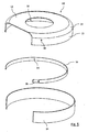
- the in the Fig. 2 and 5 Protective hood 10 shown has a disk-like upper part 12, which passes over a partially circumferential, downwardly bent portion 13 in a substantially perpendicular to the plane of the upper part 12 extending edge portion 15.
- the protective hood 10 has, in the middle of its upper part 12, a through-opening 32 in which a head, fitted with a weed brush 30, of a weed-removing device, in particular a brushcutter or a brushcutter, not illustrated, comes to rest, as shown in FIG Fig. 1 is shown schematically.
- the protective cover 12 At its downwardly, to the fixed surface extending edge portion 15, the protective cover 12 on a flexible deformable protective element 14, which is arranged as at least partially circulating belt the edge portion 15 partially overlapping the guard 10.
- the attachment of the protective element 14 to the protective cover 10 may be formed as a permanent connection.
- the protective element 14 is made of a relatively soft plastic, in particular soft PVC (PVC-P). It allows a low-friction sliding of the protective cover over the fixed surface to be cleaned. It also contributes to the minimization of an air gap or a distance between the protective hood 10 and the attached surface, so that an undesirable and uncontrolled distribution of both removed weeds, as well as on-surface objects, especially stones, can be effectively prevented.
- PVC-P soft PVC
- Fig. 2 and 5 illustrates, preferably formed of soft PVC, flexible and elastically deformable protective element 14 by means of a retaining and fastening ring 16 on the protective cover 10 can be fastened.
- the protective element 14, the retaining and fastening ring 16 and the edge portion 15 of the protective cover 10 have seen in the circumferential direction to each other corresponding geometries, so that during assembly and attachment of the Protective element 14 on the guard 10 as large as possible mutual contact surfaces are formed.
- the attachment of the protective element 14 on the edge 15 of the protective cover 10 can be effected by means of individual positive or non-positive fastening elements, in particular by means of rivets, screws and possibly with the aid of adhesives. Also, a material-locking fastening, such as a welding of edge 15 and protective element 14 come into question.
- the protective element 14 comes to rest outside on the edge 15 of the protective hood 10 and that the holding and fastening ring 16 is arranged on the outside of the protective element 14, in particular adjacent to the upper edge portion thereof.
- the protective hood 10, preferably made of a relatively hard plastic, such as polyoxymethylene (POM), and the retaining and fixing ring 16 are, as in FIG Fig. 5 illustrates, by means of alignment with each other coming mounting holes 36, 38, 34 fastened together, wherein the protective element 14 of corresponding fasteners, such as screws or rivets, interspersed and clamped between the holding and mounting ring 16 and the edge 15 of the guard 10.
- POM polyoxymethylene
- the headband 22 is pivotally connected to two opposite, fork-like downwardly projecting free end portions on the edge 15, and on the holding and fastening ring 16. It extends substantially parallel to the upper side of the upper part 12 at a distance therefrom and has two webs 26 running parallel to one another, which in turn are mounted pivotably on a receptacle 24 enclosing the drive member 28 of the brushcutter.
- a stop element 25 is disposed on the drive shaft 28 in a lower portion between the receptacle 24 and the weed brush 30, which limits the pivoting of the protective hood 10 at least in one direction.
- the in Fig. 1 illustrated configuration is the top of the upper part 12 on the underside of that stop element.
- the guard is in all in the Fig. 1 to 5 shown embodiments only as a weed brush 30 only partially enclosing or partially enclosing protective hood formed.
- an opening 18 is formed, which can be formed for example by a straight-line separation of a side edge of a cylindrical protective hood.
- the plane of the opening 18 extends tangentially to the peripheral edge 15 of the protective hood. It runs opposite to the outer circumference of an imaginary circular edge quasi radially offset inwards.
- the radial offset, or to the formation of the opening in the tangential direction extending section of the opening plane is chosen such that the protective cover an angular range of 220 ° to 300 °, in the representations of Fig. 1 to 5 encloses approximately an angular range of 270 °.
- a circular arc of about 270 ° bordered by the protective cover, while formed in the hood 10 opening 18 corresponds approximately to a circular arc segment of 90 °.
- the opening 18 allows a corresponding, targeted removal of air, which is sucked in through the opening 12 formed in the upper part 12.
- a suction effect By means of the air flow thus formed can be generated by the combination of the lateral opening 18 and the passage opening 32, a suction effect, the simplifies the handling of the brushcutter or brushcutter and contributes to a further increase in reliability. Because the suction effect can cause an advantageous depression of the brush head to the fixed surface.
Landscapes
- Life Sciences & Earth Sciences (AREA)
- Environmental Sciences (AREA)
- Harvester Elements (AREA)
- Catching Or Destruction (AREA)
Claims (14)
- Dispositif de protection pour un dispositif portable destiné à l'élimination mécanique des mauvaises herbes sur des surfaces fixes, en particulier pour une faux à moteur ou une désherbeuse, dans lequel le dispositif de protection présente un capot de protection (10) qui comporte sur son côté supérieur (12), qui est en position d'utilisation situé à l'opposé de la surface fixe, une ouverture de passage (32) pour un arbre (28) se trouvant en liaison active avec une brosse de désherbage (30) et dans lequel le capot de protection (10) entoure au moins localement en direction périphérique la brosse de désherbage (30) montée de façon rotative, dans lequel un élément de protection déformable de façon flexible (14) est disposé sur le côté inférieur du capot de protection (10) tourné vers la surface fixe dans la position d'utilisation, caractérisé en ce que l'élément de protection présente une pluralité de crins élastiquement déformables ayant leurs extrémités libres dirigées vers le bas en direction de la surface fixe.
- Dispositif de protection selon la revendication 1, dans lequel le capot de protection (10) présente une partie supérieure (12) en forme de disque orientée essentiellement parallèlement à la surface fixe dans la position d'utilisation, dans laquelle est formée l'ouverture de passage pour l'arbre (28).
- Dispositif de protection selon l'une quelconque des revendications précédentes, dans lequel le capot de protection (10) présente un bord (15), au moins localement de forme annulaire et entourant au moins localement la brosse de désherbage, sur lequel l'élément de protection (14) est disposé.
- Dispositif de protection selon l'une quelconque des revendications précédentes, dans lequel l'élément de protection est réalisé sous la forme d'une bande élastiquement déformable (14) en matière plastique, de préférence en chlorure de polyvinyle (PVC), de préférence encore en PVC souple (PVC-P).
- Dispositif de protection selon l'une quelconque des revendications précédentes, dans lequel le capot de protection (10) est fabriqué en une seule pièce en un élastomère thermoplastique.
- Dispositif de protection selon l'une quelconque des revendications précédentes, dans lequel l'élément de protection (14) repose sur le bord (15) du capot de protection (10) en formant une zone de recouvrement et est fixé au bord (15) au moyen d'un anneau de maintien (16).
- Dispositif de protection selon l'une quelconque des revendications précédentes, dans lequel le diamètre intérieur de l'ouverture de passage (32) formée dans le capot de protection (10) vaut 1/3 à 2/3, de préférence environ 1/2, du diamètre intérieur du capot de protection (10).
- Dispositif de protection selon l'une quelconque des revendications précédentes, dans lequel le capot de protection (10) et l'élément de protection flexible (14) entourent la brosse de désherbage (30) pouvant être entraînée en rotation, dans la direction périphérique sur une zone angulaire de 220 ° à 300 °, de préférence de 240° à 280°, et de préférence encore de 250° à 270°.
- Dispositif de protection selon l'une quelconque des revendications précédentes, dans lequel le capot de protection (10) présente une ouverture latérale (18) pour l'éjection des mauvaises herbes éliminées de la surface fixe.
- Dispositif de protection selon la revendication 9, dans lequel l'ouverture latérale (18) peut être fermée au moyen d'un volet rabattable vers le haut.
- Dispositif de protection selon l'une quelconque des revendications précédentes, dans lequel le capot de protection (10) peut être disposé de façon pivotante sur le dispositif portable d'élimination des mauvaises herbes.
- Dispositif de protection selon la revendication 11, dans lequel un étrier de fixation (22) est articulé sur des parties opposées du bord (15) du capot de protection pour la fixation pivotante du capot de protection (10) sur le dispositif d'élimination des mauvaises herbes.
- Dispositif de protection selon la revendication 12, dans lequel l'étrier de fixation (22), l'anneau de maintien (16) et/ou l'élément de protection flexible (14) sont assemblés les uns aux autres en un ou plusieurs point(s) de fixation commun(s) (20).
- Dispositif d'élimination des mauvaises herbes destiné à l'élimination des mauvaises herbes sur des surfaces fixes avec une brosse de désherbage (30) pouvant être entraînée par un moteur et un dispositif de protection selon l'une quelconque des revendications précédentes.
Priority Applications (3)
| Application Number | Priority Date | Filing Date | Title |
|---|---|---|---|
| ES09005387T ES2401404T3 (es) | 2009-04-15 | 2009-04-15 | Dispositivo de protección para la retirada mecánica de malas hierbas |
| DK09005387.7T DK2241173T3 (da) | 2009-04-15 | 2009-04-15 | Beskyttelsesanordning til mekanisk fjernelse af ukrudt |
| EP20090005387 EP2241173B1 (fr) | 2009-04-15 | 2009-04-15 | Dispositif de protection pour la suppression mécanique des mauvaises herbes |
Applications Claiming Priority (1)
| Application Number | Priority Date | Filing Date | Title |
|---|---|---|---|
| EP20090005387 EP2241173B1 (fr) | 2009-04-15 | 2009-04-15 | Dispositif de protection pour la suppression mécanique des mauvaises herbes |
Publications (2)
| Publication Number | Publication Date |
|---|---|
| EP2241173A1 EP2241173A1 (fr) | 2010-10-20 |
| EP2241173B1 true EP2241173B1 (fr) | 2012-12-12 |
Family
ID=41050869
Family Applications (1)
| Application Number | Title | Priority Date | Filing Date |
|---|---|---|---|
| EP20090005387 Active EP2241173B1 (fr) | 2009-04-15 | 2009-04-15 | Dispositif de protection pour la suppression mécanique des mauvaises herbes |
Country Status (3)
| Country | Link |
|---|---|
| EP (1) | EP2241173B1 (fr) |
| DK (1) | DK2241173T3 (fr) |
| ES (1) | ES2401404T3 (fr) |
Families Citing this family (2)
| Publication number | Priority date | Publication date | Assignee | Title |
|---|---|---|---|---|
| FR3041500B1 (fr) * | 2015-09-25 | 2018-02-02 | Bobitech Sas | Protection pour debroussailleuse pour tonte reglable en hauteur et bordure |
| CN214430278U (zh) * | 2020-10-20 | 2021-10-22 | 创科无线普通合伙 | 具有可调防护件的电动工具 |
Family Cites Families (5)
| Publication number | Priority date | Publication date | Assignee | Title |
|---|---|---|---|---|
| SE378346B (fr) * | 1973-06-19 | 1975-09-01 | Husqvarna Ab | |
| DE9112996U1 (de) | 1991-10-18 | 1992-01-02 | Jakob Reisländer Fabrik technischer Bürsten GmbH, 8000 München | Motorsense |
| US20050183269A1 (en) * | 2004-02-20 | 2005-08-25 | Thompson Mark W. | Guard for a grass trimming device |
| EP1746211A1 (fr) * | 2005-07-20 | 2007-01-24 | Meint Johannes Bouland | Carter de protection pour appareils de désherbage de joints |
| US20080289194A1 (en) * | 2007-05-24 | 2008-11-27 | M Group, Inc. | Trimmer skirt |
-
2009
- 2009-04-15 DK DK09005387.7T patent/DK2241173T3/da active
- 2009-04-15 ES ES09005387T patent/ES2401404T3/es active Active
- 2009-04-15 EP EP20090005387 patent/EP2241173B1/fr active Active
Also Published As
| Publication number | Publication date |
|---|---|
| DK2241173T3 (da) | 2013-03-25 |
| ES2401404T3 (es) | 2013-04-19 |
| EP2241173A1 (fr) | 2010-10-20 |
Similar Documents
| Publication | Publication Date | Title |
|---|---|---|
| EP1074341B1 (fr) | Carter de protection contre la poussière pour outil de meulage de surfaces | |
| DE2926725A1 (de) | Kuehlluftfilter fuer den brennkraftmotor, insbesondere fuer selbstfahrende landwirtschaftliche maschinen | |
| DE3421999A1 (de) | Reblaubschneidgeraet | |
| DE2639128A1 (de) | Rasenmaeher | |
| DE19525247B4 (de) | Schutzeinrichtung für einen Rasenrandschneider | |
| DE10332918B4 (de) | Gartengerät, insbesondere Fadenschneider | |
| DE102009022085A1 (de) | Einsaugvorrichtung | |
| EP2241173A1 (fr) | Dispositif de protection pour la suppression mécanique des mauvaises herbes | |
| DE102005049766B4 (de) | Handgeführter Trennschleifer | |
| EP0784922A2 (fr) | Appareil mobile pour aspirer le gazon ou les matières similaires | |
| DE29623256U1 (de) | Vorrichtung zum Entfernen von Bewuchs aus den Fugen gepflasterter Bodenflächen | |
| WO2019185123A1 (fr) | Outil pour une machine d'élimination des mauvaises herbes et machine d'élimination des mauvaises herbes | |
| DE3128479A1 (de) | Handgeraet zur abgabe von kernigem oder pulverfoermigen streugut | |
| EP3949721B1 (fr) | Dispositif de coupe | |
| EP1358787B1 (fr) | Tête de coupe pour un dispositif motorisé de coupe de végétation | |
| DE10201233B4 (de) | Vorrichtung zum Rasentrimmen | |
| DE10055473B4 (de) | Gartengerät | |
| EP4179865A1 (fr) | Tête de faucheuse à disques et procédure de fixation de la paroi périphérique de la tête de faucheuse à disques | |
| DE202005003744U1 (de) | Schutzhaube für einen motorbetriebenen Freischneider | |
| DE3042510A1 (de) | Zum absaugen von organischen abfaellen u.dgl. von strassenraendern, banketten, graeben und boeschungen dienendes sauggeraet | |
| DE2255682A1 (de) | Maehmaschine | |
| DE102019003751B3 (de) | Bambus Rasentrimmer | |
| DE29821493U1 (de) | Steinbürste zum Reinigen von Wegen und Plätzen | |
| DE10139990A1 (de) | Vorrichtung zum mechanischen Abtragen von Wildkraut | |
| DE19962365A1 (de) | Motorgerät für die Bearbeitung und Pflege von Rasen- und Wegeflächen |
Legal Events
| Date | Code | Title | Description |
|---|---|---|---|
| PUAI | Public reference made under article 153(3) epc to a published international application that has entered the european phase |
Free format text: ORIGINAL CODE: 0009012 |
|
| 17P | Request for examination filed |
Effective date: 20091210 |
|
| AK | Designated contracting states |
Kind code of ref document: A1 Designated state(s): AT BE BG CH CY CZ DE DK EE ES FI FR GB GR HR HU IE IS IT LI LT LU LV MC MK MT NL NO PL PT RO SE SI SK TR |
|
| AX | Request for extension of the european patent |
Extension state: AL BA RS |
|
| 17Q | First examination report despatched |
Effective date: 20110830 |
|
| GRAP | Despatch of communication of intention to grant a patent |
Free format text: ORIGINAL CODE: EPIDOSNIGR1 |
|
| GRAS | Grant fee paid |
Free format text: ORIGINAL CODE: EPIDOSNIGR3 |
|
| GRAA | (expected) grant |
Free format text: ORIGINAL CODE: 0009210 |
|
| AK | Designated contracting states |
Kind code of ref document: B1 Designated state(s): AT BE BG CH CY CZ DE DK EE ES FI FR GB GR HR HU IE IS IT LI LT LU LV MC MK MT NL NO PL PT RO SE SI SK TR |
|
| REG | Reference to a national code |
Ref country code: GB Ref legal event code: FG4D Free format text: NOT ENGLISH |
|
| REG | Reference to a national code |
Ref country code: CH Ref legal event code: EP |
|
| REG | Reference to a national code |
Ref country code: AT Ref legal event code: REF Ref document number: 587885 Country of ref document: AT Kind code of ref document: T Effective date: 20121215 |
|
| REG | Reference to a national code |
Ref country code: IE Ref legal event code: FG4D Free format text: LANGUAGE OF EP DOCUMENT: GERMAN |
|
| REG | Reference to a national code |
Ref country code: DE Ref legal event code: R096 Ref document number: 502009005623 Country of ref document: DE Effective date: 20130207 |
|
| REG | Reference to a national code |
Ref country code: CH Ref legal event code: NV Representative=s name: ISLER AND PEDRAZZINI AG, CH |
|
| REG | Reference to a national code |
Ref country code: DK Ref legal event code: T3 |
|
| REG | Reference to a national code |
Ref country code: ES Ref legal event code: FG2A Ref document number: 2401404 Country of ref document: ES Kind code of ref document: T3 Effective date: 20130419 |
|
| REG | Reference to a national code |
Ref country code: NL Ref legal event code: T3 |
|
| PG25 | Lapsed in a contracting state [announced via postgrant information from national office to epo] |
Ref country code: NO Free format text: LAPSE BECAUSE OF FAILURE TO SUBMIT A TRANSLATION OF THE DESCRIPTION OR TO PAY THE FEE WITHIN THE PRESCRIBED TIME-LIMIT Effective date: 20130312 Ref country code: LT Free format text: LAPSE BECAUSE OF FAILURE TO SUBMIT A TRANSLATION OF THE DESCRIPTION OR TO PAY THE FEE WITHIN THE PRESCRIBED TIME-LIMIT Effective date: 20121212 Ref country code: FI Free format text: LAPSE BECAUSE OF FAILURE TO SUBMIT A TRANSLATION OF THE DESCRIPTION OR TO PAY THE FEE WITHIN THE PRESCRIBED TIME-LIMIT Effective date: 20121212 Ref country code: SE Free format text: LAPSE BECAUSE OF FAILURE TO SUBMIT A TRANSLATION OF THE DESCRIPTION OR TO PAY THE FEE WITHIN THE PRESCRIBED TIME-LIMIT Effective date: 20121212 |
|
| REG | Reference to a national code |
Ref country code: LT Ref legal event code: MG4D |
|
| PG25 | Lapsed in a contracting state [announced via postgrant information from national office to epo] |
Ref country code: GR Free format text: LAPSE BECAUSE OF FAILURE TO SUBMIT A TRANSLATION OF THE DESCRIPTION OR TO PAY THE FEE WITHIN THE PRESCRIBED TIME-LIMIT Effective date: 20130313 Ref country code: SI Free format text: LAPSE BECAUSE OF FAILURE TO SUBMIT A TRANSLATION OF THE DESCRIPTION OR TO PAY THE FEE WITHIN THE PRESCRIBED TIME-LIMIT Effective date: 20121212 Ref country code: LV Free format text: LAPSE BECAUSE OF FAILURE TO SUBMIT A TRANSLATION OF THE DESCRIPTION OR TO PAY THE FEE WITHIN THE PRESCRIBED TIME-LIMIT Effective date: 20121212 |
|
| PG25 | Lapsed in a contracting state [announced via postgrant information from national office to epo] |
Ref country code: IS Free format text: LAPSE BECAUSE OF FAILURE TO SUBMIT A TRANSLATION OF THE DESCRIPTION OR TO PAY THE FEE WITHIN THE PRESCRIBED TIME-LIMIT Effective date: 20130412 Ref country code: EE Free format text: LAPSE BECAUSE OF FAILURE TO SUBMIT A TRANSLATION OF THE DESCRIPTION OR TO PAY THE FEE WITHIN THE PRESCRIBED TIME-LIMIT Effective date: 20121212 Ref country code: CZ Free format text: LAPSE BECAUSE OF FAILURE TO SUBMIT A TRANSLATION OF THE DESCRIPTION OR TO PAY THE FEE WITHIN THE PRESCRIBED TIME-LIMIT Effective date: 20121212 Ref country code: BG Free format text: LAPSE BECAUSE OF FAILURE TO SUBMIT A TRANSLATION OF THE DESCRIPTION OR TO PAY THE FEE WITHIN THE PRESCRIBED TIME-LIMIT Effective date: 20130312 Ref country code: SK Free format text: LAPSE BECAUSE OF FAILURE TO SUBMIT A TRANSLATION OF THE DESCRIPTION OR TO PAY THE FEE WITHIN THE PRESCRIBED TIME-LIMIT Effective date: 20121212 |
|
| PG25 | Lapsed in a contracting state [announced via postgrant information from national office to epo] |
Ref country code: RO Free format text: LAPSE BECAUSE OF FAILURE TO SUBMIT A TRANSLATION OF THE DESCRIPTION OR TO PAY THE FEE WITHIN THE PRESCRIBED TIME-LIMIT Effective date: 20121212 Ref country code: PT Free format text: LAPSE BECAUSE OF FAILURE TO SUBMIT A TRANSLATION OF THE DESCRIPTION OR TO PAY THE FEE WITHIN THE PRESCRIBED TIME-LIMIT Effective date: 20130412 Ref country code: PL Free format text: LAPSE BECAUSE OF FAILURE TO SUBMIT A TRANSLATION OF THE DESCRIPTION OR TO PAY THE FEE WITHIN THE PRESCRIBED TIME-LIMIT Effective date: 20121212 |
|
| PLBE | No opposition filed within time limit |
Free format text: ORIGINAL CODE: 0009261 |
|
| STAA | Information on the status of an ep patent application or granted ep patent |
Free format text: STATUS: NO OPPOSITION FILED WITHIN TIME LIMIT |
|
| 26N | No opposition filed |
Effective date: 20130913 |
|
| PG25 | Lapsed in a contracting state [announced via postgrant information from national office to epo] |
Ref country code: HR Free format text: LAPSE BECAUSE OF FAILURE TO SUBMIT A TRANSLATION OF THE DESCRIPTION OR TO PAY THE FEE WITHIN THE PRESCRIBED TIME-LIMIT Effective date: 20121212 Ref country code: CY Free format text: LAPSE BECAUSE OF FAILURE TO SUBMIT A TRANSLATION OF THE DESCRIPTION OR TO PAY THE FEE WITHIN THE PRESCRIBED TIME-LIMIT Effective date: 20121212 Ref country code: MC Free format text: LAPSE BECAUSE OF FAILURE TO SUBMIT A TRANSLATION OF THE DESCRIPTION OR TO PAY THE FEE WITHIN THE PRESCRIBED TIME-LIMIT Effective date: 20121212 |
|
| REG | Reference to a national code |
Ref country code: DE Ref legal event code: R097 Ref document number: 502009005623 Country of ref document: DE Effective date: 20130913 |
|
| PG25 | Lapsed in a contracting state [announced via postgrant information from national office to epo] |
Ref country code: MT Free format text: LAPSE BECAUSE OF FAILURE TO SUBMIT A TRANSLATION OF THE DESCRIPTION OR TO PAY THE FEE WITHIN THE PRESCRIBED TIME-LIMIT Effective date: 20121212 |
|
| PG25 | Lapsed in a contracting state [announced via postgrant information from national office to epo] |
Ref country code: TR Free format text: LAPSE BECAUSE OF FAILURE TO SUBMIT A TRANSLATION OF THE DESCRIPTION OR TO PAY THE FEE WITHIN THE PRESCRIBED TIME-LIMIT Effective date: 20121212 |
|
| PG25 | Lapsed in a contracting state [announced via postgrant information from national office to epo] |
Ref country code: HU Free format text: LAPSE BECAUSE OF FAILURE TO SUBMIT A TRANSLATION OF THE DESCRIPTION OR TO PAY THE FEE WITHIN THE PRESCRIBED TIME-LIMIT; INVALID AB INITIO Effective date: 20090415 Ref country code: MK Free format text: LAPSE BECAUSE OF FAILURE TO SUBMIT A TRANSLATION OF THE DESCRIPTION OR TO PAY THE FEE WITHIN THE PRESCRIBED TIME-LIMIT Effective date: 20121212 |
|
| REG | Reference to a national code |
Ref country code: FR Ref legal event code: PLFP Year of fee payment: 8 |
|
| REG | Reference to a national code |
Ref country code: FR Ref legal event code: PLFP Year of fee payment: 9 |
|
| REG | Reference to a national code |
Ref country code: FR Ref legal event code: PLFP Year of fee payment: 10 |
|
| PGFP | Annual fee paid to national office [announced via postgrant information from national office to epo] |
Ref country code: IT Payment date: 20220426 Year of fee payment: 14 Ref country code: IE Payment date: 20220425 Year of fee payment: 14 Ref country code: ES Payment date: 20220629 Year of fee payment: 14 Ref country code: DK Payment date: 20220425 Year of fee payment: 14 |
|
| PGFP | Annual fee paid to national office [announced via postgrant information from national office to epo] |
Ref country code: CH Payment date: 20220519 Year of fee payment: 14 |
|
| REG | Reference to a national code |
Ref country code: DK Ref legal event code: EBP Effective date: 20230430 |
|
| REG | Reference to a national code |
Ref country code: CH Ref legal event code: PL |
|
| PG25 | Lapsed in a contracting state [announced via postgrant information from national office to epo] |
Ref country code: LI Free format text: LAPSE BECAUSE OF NON-PAYMENT OF DUE FEES Effective date: 20230430 Ref country code: CH Free format text: LAPSE BECAUSE OF NON-PAYMENT OF DUE FEES Effective date: 20230430 |
|
| REG | Reference to a national code |
Ref country code: IE Ref legal event code: MM4A |
|
| PG25 | Lapsed in a contracting state [announced via postgrant information from national office to epo] |
Ref country code: IE Free format text: LAPSE BECAUSE OF NON-PAYMENT OF DUE FEES Effective date: 20230415 |
|
| PG25 | Lapsed in a contracting state [announced via postgrant information from national office to epo] |
Ref country code: IT Free format text: LAPSE BECAUSE OF NON-PAYMENT OF DUE FEES Effective date: 20230415 Ref country code: IE Free format text: LAPSE BECAUSE OF NON-PAYMENT OF DUE FEES Effective date: 20230415 Ref country code: DK Free format text: LAPSE BECAUSE OF NON-PAYMENT OF DUE FEES Effective date: 20230430 |
|
| REG | Reference to a national code |
Ref country code: ES Ref legal event code: FD2A Effective date: 20240529 |
|
| PG25 | Lapsed in a contracting state [announced via postgrant information from national office to epo] |
Ref country code: ES Free format text: LAPSE BECAUSE OF NON-PAYMENT OF DUE FEES Effective date: 20230416 |
|
| PG25 | Lapsed in a contracting state [announced via postgrant information from national office to epo] |
Ref country code: ES Free format text: LAPSE BECAUSE OF NON-PAYMENT OF DUE FEES Effective date: 20230416 |
|
| PGFP | Annual fee paid to national office [announced via postgrant information from national office to epo] |
Ref country code: NL Payment date: 20250418 Year of fee payment: 17 |
|
| PGFP | Annual fee paid to national office [announced via postgrant information from national office to epo] |
Ref country code: LU Payment date: 20250418 Year of fee payment: 17 |
|
| PGFP | Annual fee paid to national office [announced via postgrant information from national office to epo] |
Ref country code: DE Payment date: 20250425 Year of fee payment: 17 |
|
| PGFP | Annual fee paid to national office [announced via postgrant information from national office to epo] |
Ref country code: GB Payment date: 20250423 Year of fee payment: 17 |
|
| PGFP | Annual fee paid to national office [announced via postgrant information from national office to epo] |
Ref country code: BE Payment date: 20250418 Year of fee payment: 17 |
|
| PGFP | Annual fee paid to national office [announced via postgrant information from national office to epo] |
Ref country code: FR Payment date: 20250424 Year of fee payment: 17 |
|
| PGFP | Annual fee paid to national office [announced via postgrant information from national office to epo] |
Ref country code: AT Payment date: 20250423 Year of fee payment: 17 |