EP2241182A1 - Prise multicouche pour cannes à pêche - Google Patents
Prise multicouche pour cannes à pêche Download PDFInfo
- Publication number
- EP2241182A1 EP2241182A1 EP10250730A EP10250730A EP2241182A1 EP 2241182 A1 EP2241182 A1 EP 2241182A1 EP 10250730 A EP10250730 A EP 10250730A EP 10250730 A EP10250730 A EP 10250730A EP 2241182 A1 EP2241182 A1 EP 2241182A1
- Authority
- EP
- European Patent Office
- Prior art keywords
- sleeve
- grip
- approximately
- vinyl acetate
- ethylene vinyl
- Prior art date
- Legal status (The legal status is an assumption and is not a legal conclusion. Google has not performed a legal analysis and makes no representation as to the accuracy of the status listed.)
- Withdrawn
Links
- 239000005038 ethylene vinyl acetate Substances 0.000 claims abstract description 42
- 229920001200 poly(ethylene-vinyl acetate) Polymers 0.000 claims abstract description 42
- DQXBYHZEEUGOBF-UHFFFAOYSA-N but-3-enoic acid;ethene Chemical compound C=C.OC(=O)CC=C DQXBYHZEEUGOBF-UHFFFAOYSA-N 0.000 claims abstract description 41
- 238000000034 method Methods 0.000 claims abstract description 6
- 229920002635 polyurethane Polymers 0.000 claims description 21
- 239000004814 polyurethane Substances 0.000 claims description 21
- 238000004519 manufacturing process Methods 0.000 claims description 7
- 230000015271 coagulation Effects 0.000 claims description 6
- 238000005345 coagulation Methods 0.000 claims description 6
- 238000002347 injection Methods 0.000 claims description 5
- 239000007924 injection Substances 0.000 claims description 5
- 238000001746 injection moulding Methods 0.000 claims description 3
- 239000006260 foam Substances 0.000 claims description 2
- 210000002445 nipple Anatomy 0.000 description 18
- 239000000835 fiber Substances 0.000 description 8
- 239000000463 material Substances 0.000 description 6
- 239000000853 adhesive Substances 0.000 description 4
- 230000001070 adhesive effect Effects 0.000 description 4
- 239000004744 fabric Substances 0.000 description 4
- 230000007704 transition Effects 0.000 description 4
- 230000008901 benefit Effects 0.000 description 3
- 230000005540 biological transmission Effects 0.000 description 3
- 230000035939 shock Effects 0.000 description 3
- 239000002759 woven fabric Substances 0.000 description 3
- 239000004677 Nylon Substances 0.000 description 2
- 239000000945 filler Substances 0.000 description 2
- 239000012530 fluid Substances 0.000 description 2
- 238000012986 modification Methods 0.000 description 2
- 230000004048 modification Effects 0.000 description 2
- 229920001778 nylon Polymers 0.000 description 2
- 229920000742 Cotton Polymers 0.000 description 1
- 230000001112 coagulating effect Effects 0.000 description 1
- 239000003086 colorant Substances 0.000 description 1
- 238000005336 cracking Methods 0.000 description 1
- 230000006353 environmental stress Effects 0.000 description 1
- 239000000203 mixture Substances 0.000 description 1
- 231100000956 nontoxicity Toxicity 0.000 description 1
- 229920000728 polyester Polymers 0.000 description 1
- 230000001681 protective effect Effects 0.000 description 1
- 239000007921 spray Substances 0.000 description 1
- XLYOFNOQVPJJNP-UHFFFAOYSA-N water Substances O XLYOFNOQVPJJNP-UHFFFAOYSA-N 0.000 description 1
Images


Classifications
-
- A—HUMAN NECESSITIES
- A01—AGRICULTURE; FORESTRY; ANIMAL HUSBANDRY; HUNTING; TRAPPING; FISHING
- A01K—ANIMAL HUSBANDRY; AVICULTURE; APICULTURE; PISCICULTURE; FISHING; REARING OR BREEDING ANIMALS, NOT OTHERWISE PROVIDED FOR; NEW BREEDS OF ANIMALS
- A01K87/00—Fishing rods
- A01K87/08—Handgrips
Definitions
- Embodiments of the invention relate to an improved grip for use with the handle portion of articles, in particular, the handle portion of fishing poles.
- a grip configured for use with at least a portion of the handle portion of an article, the grip comprising an ethylene vinyl acetate sleeve including a first end, a second end, and a mounting surface extending generally therebetween and a gripping member.
- the gripping member comprises an ethylene vinyl acetate inner layer and an outer layer comprising polyurethane, the inner layer of the gripping member being adhered to the mounting surface of the sleeve.
- the article is a fishing pole.
- Some embodiments provide a method of manufacturing a sleeve for use with a grip, the method comprising the steps of injection molding a primary form of the sleeve in a first mold, the primary form of the sleeve comprising ethylene vinyl acetate. In some embodiments, the injection molded primary form of the sleeve is then removed from the first mold and a core bar is inserted into the inner cavity of the primary form of the sleeve.
- the core bar and the primary form of the sleeve are inserted into additional tooling machinery to allow for control of the temperature and time spent at the one or more temperatures to control the coagulation of the ethylene vinyl acetate such that the finished ethylene vinyl acetate as at least approximately one half as dense as the ethylene vinyl acetate injected into the primary form.
- Some embodiments provide a grip configured for use with at least a portion of the handle portion of an article which includes an ethylene vinyl acetate sleeve including a first end, a second end, and a mounting surface extending generally therebetween and a gripping member.
- the gripping member includes an ethylene vinyl acetate inner layer and an outer layer comprising polyurethane, the inner layer of the gripping member is adhered to the mounting surface of the sleeve, and wherein the ratio of the weight of the sleeve to the weight of the gripping member is less than or equal to approximately 3.
- the article is a fishing pole.
- Embodiments of the present invention include one or more advantages including offering great feel by transmitting sensitive vibrations to the hand of a user and being light in weight and of low density.
- the low density and extremely light weight allows the grip to float in water regardless of how wet it becomes.
- FIG. 1 is a perspective view of an exemplary fishing pole incorporating a grip according to some embodiments
- FIG. 2 is a front view of a grip component according to some embodiments
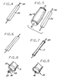
- FIG. 3 is a perspective view of a block of material for use in making the component shown in FIG. 2 according to some embodiments;
- FIG. 4 is a perspective view of the block shown in FIG. 3 on a mount for use during the manufacturing process of a grip component according to some embodiments;
- FIG. 5 is a perspective view of the mounted block shown in FIG. 4 with a grinding wheel for use during the manufacturing process of a grip component according to some embodiments;
- FIG. 6 is a perspective view of a partially shaped grip component according to some embodiments.
- FIG. 7 is a perspective view of a shaped grip component according to some embodiments.
- FIG. 8 is a perspective view of an end of the grip component shown in FIG. 7 after the mount is removed and before an end filler is applied according to some embodiments;
- FIG. 9 is a perspective view of the end shown in FIG.8 after the end filler is applied according to some embodiments.
- FIG. 10 is a perspective view of a gripping member configured for use with the grip component shown in FIG. 2 according to some embodiments;
- FIG. 11 is a section view of the gripping member shown in FIG. 10 taken along the line 11-11 in FIG. 10 ;
- FIG. 12 is an enlarged view of a portion of the gripping member designated by the circle 12 in FIG. 11 ;
- FIG. 12A is an alternative view of the portion shown in FIG. 12 according to some embodiments.
- FIG. 13 is a front view of a grip component and a gripping member during the manufacturing process according to some embodiments
- FIG. 14 is a completed grip according to some embodiments.
- FIG. 15 is a section view of the grip shown in FIG. 14 taken along the line 15-15 in FIG. 14 ;
- FIG. 16 is an enlarged view of a portion of the grip shown in FIG. 14 designated by the circle 16 in FIG. 15 according to some embodiments;
- FIG. 17 is an enlarged view of a portion of the grip shown in FIG. 14 designated by the circle 17 in FIG. 15 according to some embodiments.
- FIG. 17A is an enlarged view of an alternative configuration of the portion of the grip designated by the circle 17 in FIG. 15 according to some embodiments.
- FIG. 1 is a perspective view of a fishing pole FP incorporating a grip G according to some embodiments.
- FIG. 2 is a front view of an underlisting sleeve member 2 or sleeve according to some embodiments.
- the sleeve 2 includes a cavity 4 configured to receive at least a portion of the handle portion of a fishing pole, rod, or other article.
- the sleeve 2 further includes a first end 6 with an opening 10 adapted to receive the handle portion and a second end 8 including a substantially enclosed closed end.
- a mounting surface 12 or body extends between the first and second ends 6, 8.
- the first end 6 may include a nipple 14, which can be a stepped structure configured to accommodate a finger hook 15 of a fishing rod FP.
- the nipple 14 may be tapered to provide a smoother transition from the smaller diameter exposed handle, rod, or shaft near the nipple 14 to the main gripping portion 50 of the grip G.
- the nipple 14 may be integrally formed with the mounting surface 12 or may be separately formed and later joined to the mounting surface 12.
- the nipple 14 may define a circumferential nipple ledge 16 extending around the sleeve member 2 and extending radially outward from the mounting surface 12 of the sleeve member 2 adjacent the mounting surface 12.
- the nipple ledge 16 may comprise a nipple contact surface 18 and a nipple outer surface 20.
- the nipple outer surface 20 may transition into the tapered upper portion of the nipple 14.
- the second end 8 may include a cap structure 22.
- the cap 22 may include an opening 24 to facilitate the escape of air as a handle is inserted into the sleeve 2.
- the cap 22 may define a generally convex shape on its end.
- the cap 22 defines a circumferential cap ledge 26 extending around the sleeve member 2 and extending radially outward from the mounting surface 12 of the sleeve member 2 adjacent the mounting surface 12.
- the cap ledge 26 comprises a cap contact surface 28 and a cap outer surface 30.
- the cap 22 and nipple 14 are integrally formed with the body 12 of the sleeve 2.
- the nipple contact surface 18 extends radially from the mounting surface 12 at approximately 90 degrees. In some embodiments, the nipple contact surface 18 extends from the mounting surface 12 between approximately 45 and approximately 90 degrees. In some embodiments, the nipple contact surface 18 extends from the mounting surface 12 between approximately 90 and approximately 135 degrees.
- the cap contact surface 28 extends radially from the mounting surface 12 at approximately 90 degrees. In some embodiments, the cap contact surface 28 extends from the mounting surface 12 between approximately 45 and approximately 90 degrees. In some embodiments, the cap contact surface 28 extends from the mounting surface 12 between approximately 90 and approximately 135 degrees.
- FIGS. 3-9 illustrate a method of manufacturing a sleeve 2 according to some embodiments.
- a block 32 of ethylene-vinyl-acetate (EVA) ( FIG. 3 ) is mounted on a support rod 34 ( FIG. 4 ) to facilitate a grinding process.
- a grinder 36 desirably shaped to impart a desired configuration is brought into contact with the block 32 of EVA.
- the general shape of the grip component is formed.
- the same grinder that forms the mounting surface 12 or body of the sleeve 2 may also shape the nipple 14 and/or cap 22 if so included.
- these portions of the grip G may be formed by one or more additional grinders of appropriate shape.
- the mounting rod 34 is preferably removed.
- the mounting rod 34 has an external diameter generally equal to the external diameter of the handle portion of an article intended to be inserted into the sleeve 2.
- the hole 38 left at the second end 8 can be filled with an appropriately shaped plug 40.
- the plug 40 is made from the same material as the sleeve 2 so as to seamlessly or virtually seamlessly blend in with the sleeve 2.
- the plug 40 may be a different material to facilitate the placement of aesthetically pleasing designs, or contrasting colors or textures at the second end 8 of the sleeve 2.
- the plug 40 includes a small hole 24 or opening to permit the release of air or other fluid as described above.
- FIGS. 10-11 illustrate a gripping member 50 according to some embodiments.
- the gripping member 50 is shaped to generally correspond with the mounting surface 12 of the sleeve 2 when applied thereto. Shown as a panel P, the illustrated embodiment is folded or wrapped around the mounting surface 12 to form a substantially vertical seam 52 ( FIG. 14 ) that joins the side edges 54, 56 of the panel P as described in greater detail below.
- the gripping member 50 could be formed as a strip that would in turn be spirally wrapped around the mounting surface 12. In some embodiments, multiple panels and/or strips may be incorporated.
- FIG. 11 is a section view of the gripping member 50 taken along the line 11-11 in FIG. 10 .
- the gripping member 50 preferably includes an outer layer 58 adhered, bonded, glued or otherwise attached to a base or inner layer 60.
- the outer layer 58 defines an inner surface 62 and an outer surface 64 and is preferably polyurethane, though suitable other materials may be used.
- the inner layer 60 defines an inner surface 66 and an outer surface 68 and is preferably a polymeric material, for example ethylene vinyl acetate.
- a spray on adhesive 70 is applied to one or both of the inner surface 62 of the outer layer 58 and/or the outer surface 68 of the inner layer 60.
- the EVA sheet 60 includes an adhesive 70 that is covered with a protective sheet (not shown). The sheet is removed prior to bringing the EVA sheet 60 into contact with the bottom side 62 of the polyurethane sheet 58.
- adhesive 70 can be sprayed or otherwise applied to one or both of the bottom side 62 of the polyurethane sheet 58 and/or the EVA sheet 60.
- FIG. 12 is an enlarged view of a portion of the gripping member 50 designated by the circle 12 in FIG. 11 .
- the outer layer 58 preferably includes polyurethane.
- the polyurethane is preferably coagulated to form one or more closed cells (not shown).
- a finished grip including a polyurethane/EVA gripping member 50 adhered to an EVA sleeve 2 weighs between approximately 8 and 35 grams. In some embodiments, the finished grip G weighs between approximately 10 and 25 grams. In some embodiments, the finished grip G weighs between approximately 12 and 22 grams. In a preferred embodiment, the finished grip G weighs approximately 20 grams while still providing the desired shock transmission, tackiness and torsion resistance required of a grip for an article such as a fishing pole.
- FIG. 12A is an alternative view of the portion shown in FIG. 12 according to some embodiments.
- an additional woven fabric mesh 82 is included in the polyurethane layer 58 during the manufacturing process.
- the woven fabric mesh 82 can be stitched or otherwise joined to the backing layer (not shown) upon which the polyurethane sheet 58 is to be coagulated.
- the backing layer is nylon or another cloth with holes to permit fluid to escape from the coagulating polyurethane. The cloth permits the polyurethane to be removed prior to being included in a grip.
- the fabric mesh 82 becomes imbedded in the polyurethane and stays with the polyurethane after the backing layer is removed.
- the fabric mesh 82 includes longitudinally extending fibers (fibers that extend generally along the length of the long axis of a grip for a grip formed by a panel ( FIG. 13 ) or along the long axis of a strip where the finished grip is formed from a spirally wrapped strip) and transversely extending fibers.
- the longitudinally extending fibers will preferably be of a larger diameter than the transversely extending fibers.
- the longitudinal fibers may have a diameter between approximately 0.4 and 0.75 millimeters and the transverse fibers may have a diameter between approximately 0.25 and 0.5 millimeters.
- the longitudinal and transverse fibers may be of substantially equal diameters.
- the woven fabric mesh 82 may be fabricated of suitable materials such as nylon, cotton, polyester, or the like.
- FIGS. 13-17A show the application of a gripping member 50 or panel onto a sleeve 2 according to some embodiments.
- An adhesive 162 is sprayed onto the mounting surface 12 of the sleeve 2, the inner surface 66 of the gripping member 50 or both as shown and the panel P is wrapped around the mounting surface 12.
- the side edges 54, 56 of the panel can be skived so as to overlap along the seam 52 with like layers generally contacting and adhered to like layers as shown in FIGS. 15 and 17 .
- the side edges 54, 56 can be skived such that the outer surface 64 of the panel P at or near the side edges 54, 56 contact each other along the seam 52.
- such a seam 52 is stitched closed with the stitches 170 preferably extending through at least a portion of the polyurethane outer layer 58 and at least a portion of the EVA inner layer 60 as shown in FIG. 17A .
- the panel P is stitched inside out with the polyurethane surface 64 facing inwards and, after stitching the seam 52, the panel P is reversed as it is applied to the sleeve 2 such that, on the finished grip G, the polyurethane surface 64 is outward facing.
- the thickness 180 of the panel P corresponds generally to the distance 190 the nipple contact surface 18 extends from the mounting surface 12 to facilitate the creation of a smooth transition from the gripping member 50 to the nipple 14. In some embodiments, the thickness 180 of the panel P corresponds generally to the distance 192 the cap contact surface 28 extends from the mounting surface 12 to facilitate the creation of a smooth transition from the gripping member 50 to the cap 22.
- the EVA sleeve 2 is injection molded rather than ground down from a block 32 of EVA foam.
- Ethylene vinyl acetate copolymers possess many excellent characteristics such as low weight, low density, flexibility, transparency, non-toxicity and good resistance to environmental stress cracking, etc.
- Some embodiments of the present invention overcome the difficulties of working with injection molded EVA. For example, EVA coagulation is a relatively slow process. After injection molding a rough EVA sleeve, a core bar can be inserted inside the sleeve and the sleeve can be transferred to an appropriate mold to control the shape of the finished product. Controlling temperature and time facilitates effective control of the EVA coagulation.
- the density of the EVA injected to form the sleeve 2 is less than approximately 1 g/cm 3 . In some embodiments, the density is between approximately 0.9 and 1 g/cm 3 . In a preferred embodiment, the density is between approximately 0.930 and 0.943 g/cm 3 . Controlling the degree of coagulation of the EVA allows embodiments of the invention to include an EVA sleeve whose volume is, for example, approximately doubled or tripled from the original volume. Therefore, in some embodiments, the density of the finished sleeve 2 can be approximately one half or one third of the original density.
- the density of the finished sleeve 2 can be between approximately 0.25 and 0.75 g/cm 3 . In some embodiments, the density of the finished sleeve 2 can be between approximately 0.3 and 0.6 g/cm 3 .
- the weight of the finished sleeve 2 can be between approximately 5 and 15 g. In some embodiments, the weight of the finished sleeve 2 can be between approximately 7 and 12 g. In a preferred embodiment, the finished sleeve 2 weighs approximately 10 g. In some embodiments, the ratio of the weight of the EVA sleeve 2 to the gripping member 50 is between approximately 0.5 and 3. In some embodiments, the ratio is between approximately 0.75 and 2. In a preferred embodiment, the ratio is approximately 1.
- the ratio of the weight of the EVA sleeve 2 to the gripping member 50 is less than approximately 3, less than approximately 2.5, less than approximately 2, less than approximately 1.5, less than approximately 1, and/or less than approximately 0.5. In some embodiments, the ratio of the weight of the sleeve 2 to the gripping member 50 in the finished grip G is less than approximately 3 and the overall weight of the finished grip G is between approximately 8 and 35 grams. In a preferred embodiment, the ratio of the weight of the sleeve 2 to the gripping member 50 in the finished grip G is less than approximately 2 and the overall weight of the finished grip G is between approximately 10 and 18 grams.
Landscapes
- Life Sciences & Earth Sciences (AREA)
- Environmental Sciences (AREA)
- Marine Sciences & Fisheries (AREA)
- Animal Husbandry (AREA)
- Biodiversity & Conservation Biology (AREA)
- Fishing Rods (AREA)
Applications Claiming Priority (6)
| Application Number | Priority Date | Filing Date | Title |
|---|---|---|---|
| US16854609P | 2009-04-10 | 2009-04-10 | |
| US17721009P | 2009-05-11 | 2009-05-11 | |
| US18348409P | 2009-06-02 | 2009-06-02 | |
| US18348809P | 2009-06-02 | 2009-06-02 | |
| US12/753,669 US8518505B2 (en) | 2009-04-10 | 2010-04-02 | Multi-layered grip |
| US12/753,773 US8424236B2 (en) | 2009-05-11 | 2010-04-02 | Multi-layered grip for use with fishing poles |
Publications (1)
| Publication Number | Publication Date |
|---|---|
| EP2241182A1 true EP2241182A1 (fr) | 2010-10-20 |
Family
ID=42668280
Family Applications (1)
| Application Number | Title | Priority Date | Filing Date |
|---|---|---|---|
| EP10250730A Withdrawn EP2241182A1 (fr) | 2009-04-10 | 2010-04-08 | Prise multicouche pour cannes à pêche |
Country Status (2)
| Country | Link |
|---|---|
| EP (1) | EP2241182A1 (fr) |
| CN (1) | CN101856011B (fr) |
Citations (5)
| Publication number | Priority date | Publication date | Assignee | Title |
|---|---|---|---|---|
| US4373718A (en) * | 1980-07-11 | 1983-02-15 | Schmidt Donald H | Flexible cork handle-wrapping strip |
| GB2192550A (en) * | 1986-07-14 | 1988-01-20 | William Colman Michael Brett | Grips for handles of sporting equipment |
| US6314617B1 (en) * | 1999-08-18 | 2001-11-13 | Johnson Worldwide Associates, Inc. | Reconfigurable handle |
| US20080120893A1 (en) * | 2006-11-29 | 2008-05-29 | Keys Clyde J | Ergonomic Cushion for a Fishing Rod |
| US20080229646A1 (en) * | 2007-03-19 | 2008-09-25 | Ben Huang | Fishing pole grip |
Family Cites Families (3)
| Publication number | Priority date | Publication date | Assignee | Title |
|---|---|---|---|---|
| CN1072134A (zh) * | 1991-11-13 | 1993-05-19 | 威海市乐岛电器集团公司 | 渔竿手把生产工艺 |
| US6857971B2 (en) * | 2003-03-18 | 2005-02-22 | Ben Huang | Single panel golf club grip |
| CN2596752Y (zh) * | 2003-02-11 | 2004-01-07 | 赵国胜 | 具有减震止滑功能的握把带 |
-
2010
- 2010-04-08 EP EP10250730A patent/EP2241182A1/fr not_active Withdrawn
- 2010-04-09 CN CN201010142366.4A patent/CN101856011B/zh not_active Expired - Fee Related
Patent Citations (5)
| Publication number | Priority date | Publication date | Assignee | Title |
|---|---|---|---|---|
| US4373718A (en) * | 1980-07-11 | 1983-02-15 | Schmidt Donald H | Flexible cork handle-wrapping strip |
| GB2192550A (en) * | 1986-07-14 | 1988-01-20 | William Colman Michael Brett | Grips for handles of sporting equipment |
| US6314617B1 (en) * | 1999-08-18 | 2001-11-13 | Johnson Worldwide Associates, Inc. | Reconfigurable handle |
| US20080120893A1 (en) * | 2006-11-29 | 2008-05-29 | Keys Clyde J | Ergonomic Cushion for a Fishing Rod |
| US20080229646A1 (en) * | 2007-03-19 | 2008-09-25 | Ben Huang | Fishing pole grip |
Also Published As
| Publication number | Publication date |
|---|---|
| CN101856011B (zh) | 2014-05-28 |
| CN101856011A (zh) | 2010-10-13 |
Similar Documents
| Publication | Publication Date | Title |
|---|---|---|
| US8424236B2 (en) | Multi-layered grip for use with fishing poles | |
| US8518505B2 (en) | Multi-layered grip | |
| US20100273568A1 (en) | Ultralight grip for use with golf clubs and the like | |
| JP5805939B2 (ja) | ゴルフクラブのグリップ他用の改良されたスリーブ部材 | |
| US12290057B2 (en) | Multi-layered grip | |
| US20140366327A1 (en) | Replaceable grip and apparatus and method therefor | |
| US9090307B2 (en) | Grip for the handle of an article | |
| WO2016163555A1 (fr) | Balle | |
| EP2241182A1 (fr) | Prise multicouche pour cannes à pêche | |
| JP5727154B2 (ja) | 釣り竿用の多層グリップ | |
| EP2241354A1 (fr) | Prise multicouche pour cannes à pêche | |
| JP2010246913A (ja) | ゴルフクラブ他用の超軽量グリップ | |
| JP2010246538A5 (fr) |
Legal Events
| Date | Code | Title | Description |
|---|---|---|---|
| PUAI | Public reference made under article 153(3) epc to a published international application that has entered the european phase |
Free format text: ORIGINAL CODE: 0009012 |
|
| AK | Designated contracting states |
Kind code of ref document: A1 Designated state(s): AT BE BG CH CY CZ DE DK EE ES FI FR GB GR HR HU IE IS IT LI LT LU LV MC MK MT NL NO PL PT RO SE SI SK SM TR |
|
| AX | Request for extension of the european patent |
Extension state: AL BA ME RS |
|
| 17P | Request for examination filed |
Effective date: 20110419 |
|
| STAA | Information on the status of an ep patent application or granted ep patent |
Free format text: STATUS: THE APPLICATION HAS BEEN WITHDRAWN |
|
| 18W | Application withdrawn |
Effective date: 20120221 |