EP2241390B1 - Verfahren zur Herstellung eines Heizkörpers - Google Patents
Verfahren zur Herstellung eines Heizkörpers Download PDFInfo
- Publication number
- EP2241390B1 EP2241390B1 EP09158051A EP09158051A EP2241390B1 EP 2241390 B1 EP2241390 B1 EP 2241390B1 EP 09158051 A EP09158051 A EP 09158051A EP 09158051 A EP09158051 A EP 09158051A EP 2241390 B1 EP2241390 B1 EP 2241390B1
- Authority
- EP
- European Patent Office
- Prior art keywords
- heat dissipation
- metal base
- dissipation fins
- manufacturing
- sheet metal
- Prior art date
- Legal status (The legal status is an assumption and is not a legal conclusion. Google has not performed a legal analysis and makes no representation as to the accuracy of the status listed.)
- Not-in-force
Links
Images


Classifications
-
- B—PERFORMING OPERATIONS; TRANSPORTING
- B21—MECHANICAL METAL-WORKING WITHOUT ESSENTIALLY REMOVING MATERIAL; PUNCHING METAL
- B21D—WORKING OR PROCESSING OF SHEET METAL OR METAL TUBES, RODS OR PROFILES WITHOUT ESSENTIALLY REMOVING MATERIAL; PUNCHING METAL
- B21D28/00—Shaping by press-cutting; Perforating
- B21D28/02—Punching blanks or articles with or without obtaining scrap; Notching
- B21D28/06—Making more than one part out of the same blank; Scrapless working
-
- B—PERFORMING OPERATIONS; TRANSPORTING
- B21—MECHANICAL METAL-WORKING WITHOUT ESSENTIALLY REMOVING MATERIAL; PUNCHING METAL
- B21D—WORKING OR PROCESSING OF SHEET METAL OR METAL TUBES, RODS OR PROFILES WITHOUT ESSENTIALLY REMOVING MATERIAL; PUNCHING METAL
- B21D28/00—Shaping by press-cutting; Perforating
- B21D28/24—Perforating, i.e. punching holes
- B21D28/26—Perforating, i.e. punching holes in sheets or flat parts
-
- B—PERFORMING OPERATIONS; TRANSPORTING
- B21—MECHANICAL METAL-WORKING WITHOUT ESSENTIALLY REMOVING MATERIAL; PUNCHING METAL
- B21D—WORKING OR PROCESSING OF SHEET METAL OR METAL TUBES, RODS OR PROFILES WITHOUT ESSENTIALLY REMOVING MATERIAL; PUNCHING METAL
- B21D53/00—Making other particular articles
- B21D53/02—Making other particular articles heat exchangers or parts thereof, e.g. radiators, condensers fins, headers
- B21D53/04—Making other particular articles heat exchangers or parts thereof, e.g. radiators, condensers fins, headers of sheet metal
-
- B—PERFORMING OPERATIONS; TRANSPORTING
- B21—MECHANICAL METAL-WORKING WITHOUT ESSENTIALLY REMOVING MATERIAL; PUNCHING METAL
- B21K—MAKING FORGED OR PRESSED METAL PRODUCTS, e.g. HORSE-SHOES, RIVETS, BOLTS OR WHEELS
- B21K25/00—Uniting components to form integral members, e.g. turbine wheels and shafts, caulks with inserts, with or without shaping of the components
-
- F—MECHANICAL ENGINEERING; LIGHTING; HEATING; WEAPONS; BLASTING
- F21—LIGHTING
- F21V—FUNCTIONAL FEATURES OR DETAILS OF LIGHTING DEVICES OR SYSTEMS THEREOF; STRUCTURAL COMBINATIONS OF LIGHTING DEVICES WITH OTHER ARTICLES, NOT OTHERWISE PROVIDED FOR
- F21V29/00—Protecting lighting devices from thermal damage; Cooling or heating arrangements specially adapted for lighting devices or systems
- F21V29/50—Cooling arrangements
- F21V29/70—Cooling arrangements characterised by passive heat-dissipating elements, e.g. heat-sinks
- F21V29/74—Cooling arrangements characterised by passive heat-dissipating elements, e.g. heat-sinks with fins or blades
- F21V29/77—Cooling arrangements characterised by passive heat-dissipating elements, e.g. heat-sinks with fins or blades with essentially identical diverging planar fins or blades, e.g. with fan-like or star-like cross-section
- F21V29/773—Cooling arrangements characterised by passive heat-dissipating elements, e.g. heat-sinks with fins or blades with essentially identical diverging planar fins or blades, e.g. with fan-like or star-like cross-section the planes containing the fins or blades having the direction of the light emitting axis
-
- H—ELECTRICITY
- H10—SEMICONDUCTOR DEVICES; ELECTRIC SOLID-STATE DEVICES NOT OTHERWISE PROVIDED FOR
- H10W—GENERIC PACKAGES, INTERCONNECTIONS, CONNECTORS OR OTHER CONSTRUCTIONAL DETAILS OF DEVICES COVERED BY CLASS H10
- H10W40/00—Arrangements for thermal protection or thermal control
- H10W40/01—Manufacture or treatment
- H10W40/03—Manufacture or treatment of arrangements for cooling
- H10W40/037—Assembling together parts thereof
-
- F—MECHANICAL ENGINEERING; LIGHTING; HEATING; WEAPONS; BLASTING
- F21—LIGHTING
- F21K—NON-ELECTRIC LIGHT SOURCES USING LUMINESCENCE; LIGHT SOURCES USING ELECTROCHEMILUMINESCENCE; LIGHT SOURCES USING CHARGES OF COMBUSTIBLE MATERIAL; LIGHT SOURCES USING SEMICONDUCTOR DEVICES AS LIGHT-GENERATING ELEMENTS; LIGHT SOURCES NOT OTHERWISE PROVIDED FOR
- F21K9/00—Light sources using semiconductor devices as light-generating elements, e.g. using light-emitting diodes [LED] or lasers
-
- F—MECHANICAL ENGINEERING; LIGHTING; HEATING; WEAPONS; BLASTING
- F21—LIGHTING
- F21V—FUNCTIONAL FEATURES OR DETAILS OF LIGHTING DEVICES OR SYSTEMS THEREOF; STRUCTURAL COMBINATIONS OF LIGHTING DEVICES WITH OTHER ARTICLES, NOT OTHERWISE PROVIDED FOR
- F21V29/00—Protecting lighting devices from thermal damage; Cooling or heating arrangements specially adapted for lighting devices or systems
- F21V29/85—Protecting lighting devices from thermal damage; Cooling or heating arrangements specially adapted for lighting devices or systems characterised by the material
- F21V29/89—Metals
-
- F—MECHANICAL ENGINEERING; LIGHTING; HEATING; WEAPONS; BLASTING
- F21—LIGHTING
- F21Y—INDEXING SCHEME ASSOCIATED WITH SUBCLASSES F21K, F21L, F21S and F21V, RELATING TO THE FORM OR THE KIND OF THE LIGHT SOURCES OR OF THE COLOUR OF THE LIGHT EMITTED
- F21Y2115/00—Light-generating elements of semiconductor light sources
- F21Y2115/10—Light-emitting diodes [LED]
-
- F—MECHANICAL ENGINEERING; LIGHTING; HEATING; WEAPONS; BLASTING
- F28—HEAT EXCHANGE IN GENERAL
- F28F—DETAILS OF HEAT-EXCHANGE AND HEAT-TRANSFER APPARATUS, OF GENERAL APPLICATION
- F28F3/00—Plate-like or laminated elements; Assemblies of plate-like or laminated elements
- F28F3/02—Elements or assemblies thereof with means for increasing heat-transfer area, e.g. with fins, with recesses, with corrugations
-
- H—ELECTRICITY
- H10—SEMICONDUCTOR DEVICES; ELECTRIC SOLID-STATE DEVICES NOT OTHERWISE PROVIDED FOR
- H10W—GENERIC PACKAGES, INTERCONNECTIONS, CONNECTORS OR OTHER CONSTRUCTIONAL DETAILS OF DEVICES COVERED BY CLASS H10
- H10W40/00—Arrangements for thermal protection or thermal control
- H10W40/20—Arrangements for cooling
- H10W40/22—Arrangements for cooling characterised by their shape, e.g. having conical or cylindrical projections
- H10W40/226—Arrangements for cooling characterised by their shape, e.g. having conical or cylindrical projections characterised by projecting parts, e.g. fins to increase surface area
Definitions
- the present invention relates to a method of manufacturing a radiator, in particular, to a method of manufacturing a radiator that assembles heat dissipation fins on a metal base.
- LED Light Emitting Diode
- Temperatures of the LED module of the LED lamp must be controlled lower than 80 degree Celsius in order to transform the electricity into luminous energy, not thermal energy. That is why the LED lamps have the features of low energy consumption and low heat production. Therefore, the LED lamps are usually equipped with several heat dissipation fins so as to help the LED module quickly dissipating heat.
- a radiator comprising a metal base and a plurality of heat dissipating fins is known for example from CN 201 159 402 Y .
- radiators in the market are mainly categorized into stacked fins and extruded aluminum fins etc.
- the stacked fins have a plurality of fins connected in series, but the stacked fins can form a ring-shaped body by connecting the first and the last fins, and then be further welded onto a metal base plate to form a radiator; but, after the welding process, the welded joints between the fins and the metal base plate will increase the thermal resistance of the radiator so that it is hard to meet the requirements of the high thermal conductivity. It also requires two phrases refining process, which wastes time and labors, and increases manufacturing cost.
- the extruded aluminum fins are made first by manufacturing a set of extruded aluminum mold; after extruded out, the aluminum is then cut according to the needed fin size; then, the burrs of the fins are removed by a polish process; finally, the appearances of the fins are beautified by a anodizing treatment.
- the entire procedures are complicated so that the yield is hard to increase, and the overall costs are high.
- the present invention is provided, because of the above specified disadvantages of the prior art and based on hands on experience plus academic research and developments, to effectively improve the advantages described above.
- a main object of the present invention is to provide a method for manufacturing a radiator.
- the method increases the manufacturing speed, reduces unnecessary assembly processes, largely improves the yield, and decreases the costs, etc.
- the present invention provides a method for manufacturing a radiator having a metal base and a plurality of heat dissipation fins.
- the method comprises a rotating and removing mechanism and preparation, alignment, punching, bending, and shearing and riveting steps. The shearing and riveting and the rotating steps are repeated for a predetermined times.
- the preparation step is that placing a metal base on a manufacturing fixture of an aligning-and-moving mechanism of a manufacturing machine having a sheet metal.
- the metal base has a plurality of slots formed on the periphery of the metal base, and the number of the slots is defined as Y.
- the alignment step is that moving the manufacturing fixture and the metal base to a position under the sheet metal by the aligning-and-moving mechanism.
- the punching step is first to punch two side-portions of the sheet metal to form a plurality of positioning holes, which the positioning holes are spaced apart by equal distance. A locating pin is then inserted into the located hole. Thereafter, continuously punch the sheet metal to form a plurality of heat dissipation fins on the sheet metal, which the number of the heat dissipation fins is defined as X.
- the bending step is to bend the heat dissipation fins downwards.
- the shearing and riveting step is that first moving the sheet metal by the manufacturing machine to align one of the heat dissipation fins with one of the slots; then, shearing the heat dissipation fin by a shearing die of the manufacturing machine; the heat dissipation fin is inserted into the slot by the shearing die.
- the rotating step is to rotate the manufacturing fixture so as to rotate the metal base 1/Y round.
- the shearing and riveting step is repeated for X-1 times, and the rotating step is repeated for Y-1 times.
- the rest of the heat dissipation fins of the sheet metal are orderly assembled with the Y-1 slots.
- the removing step is to remove the metal base and the heat dissipation fins, after assembly, from the manufacturing fixture. A radiator is achieved.
- the efficacy of the present invention is as follows. Via the sheet metal being continuously punched to form the heat dissipation fins in the manufacturing machine, and the heat dissipation fins being orderly inserted into and riveted with the metal base, a radiator can be assembled in an automatic process.
- the automatic process eliminates the need of a welding process to weld the heat dissipation fins on the metal base, so that thermal resistance problems can be avoided.
- the radiator can be manufactured faster, and the unnecessary assembling steps of the radiator can be reduced. Comparing the traditional method for manufacturing the extruded aluminum fins, the method of present invention is simpler and faster, so the yield of the radiator can be improved largely, and the costs of the radiator can be decreased.
- Figure 1 is a flowchart diagram according to a preferred embodiment of the present invention.
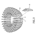
- Figure 2 is a perspective view showing a radiator according to a preferred embodiment of the present invention.
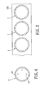
- Figure 3 is a schematic view showing a plurality of metal bases at a metal plate according to a preferred embodiment of the present invention
- Figure 4 is a top view of a metal base after being stamped according to a preferred embodiment of the present invention.
- Figure 5 is a top view of a manufacturing machine according to a preferred embodiment of the present invention.
- Figure 6 is a side view of the manufacturing machine according to a preferred embodiment of the present invention.
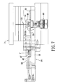
- Figure 7 is another side view of the manufacturing machine according to a preferred embodiment of the present invention, which shows a shearing die is moved down;
- Figure 8 is a front view of the manufacturing machine according to a preferred embodiment of the present invention, which shows a heat dissipation fin is inserted into the metal base;
- Figure 9 is a schematic view showing two riveting blades are aimed to press the metal base according to a preferred embodiment of the present invention.
- Figure 10 is another top view of the manufacturing machine according to a preferred embodiment of the present invention, which shows an assembled radiator is pushed off by the next pending manufacturing fixture.
- an embodiment of the present invention discloses a method for manufacturing a radiator.
- the method includes automatically manufacturing a radiator having a metal base 1 and a plurality of heat dissipation fins 51.
- the method comprises a preparing step (S 100), an aligning step (S200), a punching step (S300), a bending step (S400), a shearing and riveting step (S500), a rotating step (S600), repeating the shearing and riveting step (S500), the rotating step (S600), and a removing step (S700).
- a number of the heat dissipation fins 51 are defined as X, which the X is a natural number.
- the metal base 1 is a round plate, and manufactured by a stamping process.
- the metal base has a plurality of slots 11 and a plurality of positioning holes 12.
- the slots 11 are formed on the periphery of the metal base 1.
- a number of the slots 11 is defined as Y, which is corresponding to the number X of the heat dissipation fins 51.
- a metal plate 100 is punched by a stamping process so as to continuously or at the same time one stamping form a plurality of metal bases 1.
- the Y slots 11 are also one stamping formed at the periphery of the metal base 1.
- Using the stamping process forming the metal base 1 possesses, on the one hand, the advantage of fast manufacturing and, on the other hand, the metal base 1 with the positioning holes 12 by stamping.
- the preparing step (S100) is as follows.
- the metal base 1 is manually placed on a manufacturing fixture 40 of an aligning-and-moving mechanism 30 of a manufacturing machine 3, which the manufacturing machine 3 has a sheet metal 50.
- the manufacturing fixture 40 has a plurality of positioning columns 41.
- the positioning column 41 are inserted into the positioning hole 12 of the metal base 1, so that the metal base 1 is located and fixed at the manufacturing fixture 40.
- the aligning-and-moving mechanism 30 comprises a frame 31, a pulling arm 32, and a slide rail assembly 33.
- the frame 31 is mounted at one end of the manufacturing machine 3.
- the pulling arm 32 is movably assembled with the frame 31.
- the slide rail assembly 33 is mounted at the frame 31 and the manufacturing machine 3.
- a slide chute 42 is provided at the bottom of the manufacturing fixture 40 for engaging with the slide rail assembly 33.
- the pulling arm 32 is used for pushing the manufacturing fixture 40 sliding on the slide rail assembly 33 to a position under the sheet metal 50.
- the aligning step (S200) is as follows.
- the manufacturing fixture 40 and the metal base 1 are moved to the position under the sheet metal 50 by the aligning-and-moving mechanism 30.
- the fixture 40 and the metal 1 base are pushed by the pulling arm 32, and then slid on the slide rail assembly 33 to the position under the sheet metal 50.
- the punching step (S300) is as follows. Two opposite side-portions of the sheet metal 50 are first punched to form a plurality of positioning holes 52 by a punching mechanism (not shown). The positioning holes 52 are spaced apart by equal distance, as shown at "A" portion of Figure 5 . A locating pin (not shown) is inserted into the positioning hole 52, so that the sheet metal 50 can be accurately located and not to be moved. The sheet metal 50 is continuously punched to form the heat dissipation fins 51 by the punching mechanism, as shown at "D" portion of Figure 5 .
- the sheet metal 50 are respectively embossed to form two embossments 53, one of the two embossments 53 is on the top surface of the sheet metal 50, the other one is on the bottom surface of the sheet metal 50, as shown at "B" portion of Figure 5 .
- the embossments 53 increase the heat dissipation area of the heat dissipation fin 51.
- the sheet metal 50 is punched to form a punched slot 54, as shown at "C" portion of Figure 5 . But the punched slot 54 is optional for the heat dissipation fin 51.
- the sheet metal 50 is punched to stamp the predetermined shape at one-end of the heat dissipation fin 51, and then stamp the predetermined shape at another end of the heat dissipation fin 51, as shown at "D" portion of Figure 5 .
- the left end portion of the heat dissipation fin 51 is stamped first; then, stamp the right end portion.
- the sharp burrs of the heat dissipation fin 51 which are produced via that stamping the predetermined shapes of the heat dissipation fin 51, are removed from the heat dissipation fin 51, as shown in "E" portion of Figure 5 .
- the bending step (S400) (as shown in "F" portion) is to bend the abovementioned heat dissipation fin 51 downwards, and one end of the heat dissipation fin 51 is still connected to the sheet metal 50.
- the shearing and riveting step is as follows.
- the heat dissipation fins 51 on the sheet metal 50 are moved by the manufacturing machine 3. Hence, one of the heat dissipation fins 51 can be aligned with one of the slots 11.
- the heat dissipation fin 51 is then sheared and inserted into the slot 11 by a shearing die 60 of the manufacturing machine 3.
- the shearing die 60 has a vertically movable shearing punch 61 for the uses of shearing the heat dissipation fins 51 of the sheet metal 50, and inserting the heat dissipation fins 51 into the corresponding slots 11 of the metal base 1.
- the manufacturing fixture 40 is connected with a servo rotating mechanism 80 located under the manufacturing fixture 40.
- the manufacturing machine 3 has two riveting blades 70.
- the top surface and the bottom surface of the metal base 1 at two sides of the slot 11 are pressed from two directions by the two riveting blades 70 of the manufacturing machine 3 so that a plastic deformation happened to the metal base 1.
- the plastic deformation causes the two side-walls of the slot 11 tightly contacted the two vertical opposite surfaces of the heat dissipation fin 51 so that the heat dissipation fin 51 can be fixed with the metal base 1.
- the rotating step (S600) is performed after the abovementioned steps.
- the manufacturing fixture 40 is rotated, according to the number Y of the slots 11, 1/Y rounds, then, give order to the next slot 11 to align with the next heat dissipation fin 51 ready to be inserted into the slot 11.
- the heat dissipation fins 51 on the sheet metal 50 can be orderly assembled in the (Y-1) slots 11.
- the removing step is to remove the assembled metal base 1 and heat dissipation fins 51 from the manufacturing fixture 40 so as to obtain a radiator.
- the aligning step (S200) After the aligning step (S200) is done, the next manufacturing fixture 40' and a metal base 1' can now be placed on the aligning-and-moving mechanism 30, during any of the subsequent steps, to form a preparation step.
- the aligning step (S200) can be repeated again.
- the assembled radiator and the manufacturing fixture 40 are pushed off the sheet metal 50 by the ready manufacturing fixture 40'.
- the removal step (700) and the following steps of the aligning step (S200) can be completed. That is, large quantity of radiators can be manufactured quickly.
- the metal base 1 is a round plate and the round shape is good for inserting the heat dissipation fins 51 into the slots 11 of the metal base 1 in an orderly and accurate fashion, and also good for the rotating step (S600) to accurately rotate 1/Y times.
- the natural number X is preferably greater than ten. If X if smaller than ten, the heat dissipation provided by the heat dissipation fins 51 is less effective. In the present preferred embodiment, there are thirty heat dissipation fins 51 of the radiator. Therefore, the X is equal to 30, and the metal base 1 has thirty slots 11. Accordingly, the heat dissipation fin 51 will be riveted in the slot 11 for thirty times by the manufacturing tool 3.
- the manufacturing fixture 40 is connected with the servo rotating mechanism 80 located under the manufacturing fixture 40, which causes the metal base 1 to steppingly rotate 1/Y times at each of the Y slot 11.
- the present invention has made the sheet metal 50 continuously punched to form the heat dissipation fins 51 in the manufacturing machine 3, and the heat dissipation fins 51 orderly inserted into and riveted with the metal base 1,so that the radiator can be manufactured in an automatic process. Accordingly, there is no need to weld the heat dissipation fins 51 on the metal base 1, which avoids the thermal resistance problems induced by welding processes. Further the radiator can be manufactured faster, and the unnecessary assembling steps of the radiator are reduced. Comparing the traditional method for manufacturing the extruded aluminum fins, the method of present invention is simpler and faster. So the yield of the radiator can be improves largely, and the costs of the radiator are decreased.
Landscapes
- Engineering & Computer Science (AREA)
- Mechanical Engineering (AREA)
- General Engineering & Computer Science (AREA)
- Cooling Or The Like Of Semiconductors Or Solid State Devices (AREA)
- Cooling Or The Like Of Electrical Apparatus (AREA)
Claims (9)
- Ein Verfahren zur Herstellung eines Heizkörpers, welcher einen Metallgrundkörper (1) und eine Vielzahl von Wärmeabführlamellen (51) aufweist, umfassend:Bereitstellen eines Metallgrundkörpers (1) und Positionieren von diesem an einer Verarbeitungsfixierung (40) eines Justier- und Bewegungs-Mechanismus (30) einer Verarbeitungsmaschine (3), wobei der Metallgrundkörper (1) eine Vielzahl von Schlitzen (11) an dem Umfang des Metallgrundkörpers (1) aufweist, eine Anzahl der Schlitze (11) mit Y definiert ist, und die Verarbeitungsmaschine (3) ein Metallblech (50) aufweist;dadurch gekennzeichnet, dassdie Verarbeitungsfixierung (40) und der Metallgrundkörper (1) zu einer Position unter dem Metallblech (50) justiert und bewegt werden;zur Ausbildung einer Vielzahl von Positionierungslöchern (52) zwei Seitenabschnitte des Metallblechs (50) gestanzt werden, wobei die Positionierungslöcher (52) in einer gleichbleibenden Entfernung beabstandet voneinander angeordnet sind, ein Führungspin in dem Positionierungsloch (52) eingeführt wird, das Metallblech (50) kontinuierlich gestanzt wird, um eine Vielzahl von Wärmeabführlamellen (51) zu formen, wobei eine Anzahl an Wärmeabführlamellen (51) mit X definiert ist;die Wärmeabführlamellen (51) nach unten gebogen werden, wobei ein Ende der Wärmeabführlamellen (51) mit dem Metallblech (50) verbunden bleibt;die Wärmeabführlamellen (51), welche durch die Verarbeitungsmaschine (3) bewegt werden, geschnitten und genietet werden, wobei, wenn eines der Wärmeabführlamellen (51) zu einem der Schlitze (11) justiert wird, die Wärmeabführlamelle (51) geschnitten und mittels eines Schneidwerkzeuges (60) der Verarbeitungsmaschine (3) in den Schlitz (11) eingefügt wird, eine Oberseitenfläche und eine Unterseitenfläche des Metallgrundkörpers (1) an zwei Seiten des Schlitzes (11) mittels eines Nietwerkzeugs (70) der Verarbeitungsmaschine (3) derart gepresst wird, dass eine plastische Deformation an dem Metallgrundkörper (1) ausgebildet wird und zwei Seitenwände des Schlitzes (11) mit zwei gegenüberliegenden Oberflächen der Wärmeabführlamelle (51) fest verbunden werden;die Verarbeitungsfixierung (40) gedreht wird, wobei der Metallgrundkörper (1) um einen 1/Y Kreis gedreht wird;das Schneiden und Nieten für X-1 Male wiederholt wird, und das Drehen für Y-1 Male wiederholt wird, so dass der Rest der Wärmeabführlamellen (51) des Metallblechs (50) nach der Reihe in den Y-1 Schlitzen (11) montiert werden; undder Metallgrundkörper (1) und die Wärmeabführlamellen (51) nach dem Montieren von der Verarbeitungsfixierung (40) entfernt werden, um einen Heizkörper auszubilden.
- Das Verfahren nach Anspruch 1, wobei die Anzahl der Wärmeabführlamellen (51) größer als zehn ist.
- Das Verfahren nach Anspruch 1, wobei, nachdem die Positionierungslöcher (52) in dem Metallblech (50) ausgebildet worden sind, das Metallblech (50) von einem Prägewerkzeug (53) an der Oberseitenfläche oder der Unterseitenfläche geprägt wird.
- Das Verfahren nach Anspruch 1, wobei, nachdem die Wärmeabführlamellen (51) an dem Metallblech (50) ausgebildet worden sind, an den Wärmeabführlamellen (51) ausgebildete Grate abgeschnitten und von den Wärmeabführlamellen (51) entfernt werden.
- Das Verfahren nach Anspruch 1, wobei die Verarbeitungsfixierung (40) mit einem Servodrehmechanismus (80), der unter der Verarbeitungsfixierung (40) angeordnet ist, verbunden ist, und der Metallgrundkörper (1) schrittweise um einen 1/Y Kreis dreht.
- Das Verfahren nach Anspruch 1 weiter umfassend: Bereitstellen einer betriebsbereiten Verarbeitungsfixierung (40`) und eines betriebsbereiten Metallgrundkörpers (1') nach dem Justieren; wobei, wenn der Heizkörper montiert wurde und das Justieren einmal wiederholt wurde, der Heizkörper und die Verarbeitungsfixierung (40) mittels der betriebsbereiten Verarbeitungsfixierung (40`) geschoben werden, damit diese die Position unter dem Metallblech (50) verlassen.
- Das Verfahren nach Anspruch 1, wobei die Verarbeitungsfixierung (40) eine Positionierungssäule (41) und der Metallgrundkörper (1) ein Positionierungsloch (12) aufweisen, wobei die Positionierungssäule (41) in das Positionierungsloch (12) des an der Verarbeitungsfixierung (40) angeordneten Metallgrundkörpers (1) eingeführt wird.
- Das Verfahren nach Anspruch 1, wobei der Metallgrundkörper (1) eine runde Platte ist.
- Das Verfahren nach Anspruch 1, wobei das Schneidwerkzeug (60) einen vertikal bewegbaren Schneidstempel (61) zum Schneiden der Wärmeabführlamellen (51) von dem Metallblech (50) und zum Einfügen der Wärmabführlamellen (51) in die entsprechenden Schlitze (11) des Metallgrundkörpers (1) aufweist.
Priority Applications (1)
| Application Number | Priority Date | Filing Date | Title |
|---|---|---|---|
| EP09158051A EP2241390B1 (de) | 2009-04-16 | 2009-04-16 | Verfahren zur Herstellung eines Heizkörpers |
Applications Claiming Priority (1)
| Application Number | Priority Date | Filing Date | Title |
|---|---|---|---|
| EP09158051A EP2241390B1 (de) | 2009-04-16 | 2009-04-16 | Verfahren zur Herstellung eines Heizkörpers |
Publications (2)
| Publication Number | Publication Date |
|---|---|
| EP2241390A1 EP2241390A1 (de) | 2010-10-20 |
| EP2241390B1 true EP2241390B1 (de) | 2012-08-08 |
Family
ID=41719116
Family Applications (1)
| Application Number | Title | Priority Date | Filing Date |
|---|---|---|---|
| EP09158051A Not-in-force EP2241390B1 (de) | 2009-04-16 | 2009-04-16 | Verfahren zur Herstellung eines Heizkörpers |
Country Status (1)
| Country | Link |
|---|---|
| EP (1) | EP2241390B1 (de) |
Families Citing this family (3)
| Publication number | Priority date | Publication date | Assignee | Title |
|---|---|---|---|---|
| CN102172721B (zh) * | 2011-01-27 | 2012-09-26 | 高密市中亚暖通设备有限公司 | 散热器铆接机 |
| CN107155283B (zh) * | 2017-05-31 | 2023-04-18 | 昆山江鸿精密电子有限公司 | 多角度散热片组成型方法及散热器 |
| CN117564171B (zh) * | 2024-01-15 | 2024-04-05 | 广州坤江汽车配件工业制造有限公司 | 异形散热器主板镶块式加工装置及其加工方法 |
Citations (1)
| Publication number | Priority date | Publication date | Assignee | Title |
|---|---|---|---|---|
| WO2010131828A1 (ko) * | 2009-05-15 | 2010-11-18 | Kwon Byeng-Il | 결합 일체형 프레스장치 |
Family Cites Families (7)
| Publication number | Priority date | Publication date | Assignee | Title |
|---|---|---|---|---|
| CA2466688A1 (en) * | 2004-04-30 | 2005-10-30 | Dana Canada Corporation | Apparatus and method for forming shaped articles |
| US20060054311A1 (en) * | 2004-09-15 | 2006-03-16 | Andrew Douglas Delano | Heat sink device with independent parts |
| TW200934362A (en) * | 2008-01-16 | 2009-08-01 | Neng Tyi Prec Ind Co Ltd | Method of manufacturing heat dissipaters having heat sinks and structure thereof |
| TWM336390U (en) * | 2008-01-28 | 2008-07-11 | Neng Tyi Prec Ind Co Ltd | LED lamp |
| TWM337229U (en) * | 2008-02-01 | 2008-07-21 | Neng Tyi Prec Ind Co Ltd | Heat dissipating element and heat radiator containing the same |
| CN201159402Y (zh) * | 2008-02-20 | 2008-12-03 | 能缇精密工业股份有限公司 | 发光二极管灯具 |
| CN201163855Y (zh) * | 2008-03-03 | 2008-12-10 | 能缇精密工业股份有限公司 | 散热组件及具有该散热组件的散热器 |
-
2009
- 2009-04-16 EP EP09158051A patent/EP2241390B1/de not_active Not-in-force
Patent Citations (1)
| Publication number | Priority date | Publication date | Assignee | Title |
|---|---|---|---|---|
| WO2010131828A1 (ko) * | 2009-05-15 | 2010-11-18 | Kwon Byeng-Il | 결합 일체형 프레스장치 |
Also Published As
| Publication number | Publication date |
|---|---|
| EP2241390A1 (de) | 2010-10-20 |
Similar Documents
| Publication | Publication Date | Title |
|---|---|---|
| US8365407B2 (en) | Radiator manufacturing method and aligning-and-moving mechanism thereof | |
| US8499451B2 (en) | Method for assembling heat sink | |
| KR101727271B1 (ko) | 코루게이트핀의 제조 장치 | |
| EP2241390B1 (de) | Verfahren zur Herstellung eines Heizkörpers | |
| CN101829740B (zh) | 散热器的制造方法 | |
| WO2011092803A1 (ja) | 切断装置 | |
| CN111633130A (zh) | 散热片自动铆合设备及铆合方法 | |
| JP4929364B2 (ja) | コルゲートフィン製造装置 | |
| KR100697599B1 (ko) | 코루게이트 핀 제조장치 | |
| CN100455374C (zh) | 热导管与散热鳍片的自动化组装设备 | |
| CN101254579A (zh) | 柱状散热器的制造方法 | |
| TW201030305A (en) | Manufacturing method of heat sink, the aligning/moving mechanism for the manufacturing method, and the shearing mold | |
| CN112475062B (zh) | 一种热管散热器的自动装配生产线 | |
| JP2010245215A (ja) | 放熱器の製造方法、この製造方法により製造する放熱器、この製造方法に用いる位置合わせ移動機構並びに切断モジュール | |
| JP3930869B2 (ja) | 半導体パッケージ用アイレットの製造方法及びその製造用プレス金型 | |
| CN215657292U (zh) | 一种散热片切齿切边一次冲切成形模具 | |
| CN212703986U (zh) | 一种用于铝型材电子散热器加工的冲孔模具 | |
| CN210702209U (zh) | 一种插片式散热器的压齿装置 | |
| CN210547327U (zh) | 灯壳散热座旋切模具 | |
| CN202097295U (zh) | 一种卷圆成型模具 | |
| CN101513661A (zh) | 散热器制造方法及散热器结构 | |
| JPH0380571B2 (de) | ||
| CN1263561C (zh) | 一种插片式散热器的制造方法 | |
| KR100479917B1 (ko) | 포밍및피어싱공정동시성형금형및이를이용한열교환기용냉각판제조방법 | |
| CN209969400U (zh) | 一种散热片自动扣合模具 |
Legal Events
| Date | Code | Title | Description |
|---|---|---|---|
| PUAI | Public reference made under article 153(3) epc to a published international application that has entered the european phase |
Free format text: ORIGINAL CODE: 0009012 |
|
| AK | Designated contracting states |
Kind code of ref document: A1 Designated state(s): AT BE BG CH CY CZ DE DK EE ES FI FR GB GR HR HU IE IS IT LI LT LU LV MC MK MT NL NO PL PT RO SE SI SK TR |
|
| AX | Request for extension of the european patent |
Extension state: AL BA RS |
|
| 17P | Request for examination filed |
Effective date: 20110121 |
|
| 17Q | First examination report despatched |
Effective date: 20110215 |
|
| GRAP | Despatch of communication of intention to grant a patent |
Free format text: ORIGINAL CODE: EPIDOSNIGR1 |
|
| RIC1 | Information provided on ipc code assigned before grant |
Ipc: F21Y 101/02 20060101ALN20120116BHEP Ipc: B21D 53/04 20060101AFI20120116BHEP Ipc: B21J 15/00 20060101ALI20120116BHEP Ipc: H01L 23/367 20060101ALI20120116BHEP Ipc: B21D 28/06 20060101ALI20120116BHEP Ipc: F21V 29/00 20060101ALI20120116BHEP Ipc: B21D 28/26 20060101ALI20120116BHEP |
|
| RTI1 | Title (correction) |
Free format text: RADIATOR MANUFACTURING METHOD |
|
| GRAS | Grant fee paid |
Free format text: ORIGINAL CODE: EPIDOSNIGR3 |
|
| GRAA | (expected) grant |
Free format text: ORIGINAL CODE: 0009210 |
|
| AK | Designated contracting states |
Kind code of ref document: B1 Designated state(s): AT BE BG CH CY CZ DE DK EE ES FI FR GB GR HR HU IE IS IT LI LT LU LV MC MK MT NL NO PL PT RO SE SI SK TR |
|
| REG | Reference to a national code |
Ref country code: GB Ref legal event code: FG4D |
|
| REG | Reference to a national code |
Ref country code: AT Ref legal event code: REF Ref document number: 569471 Country of ref document: AT Kind code of ref document: T Effective date: 20120815 Ref country code: CH Ref legal event code: EP |
|
| REG | Reference to a national code |
Ref country code: IE Ref legal event code: FG4D |
|
| REG | Reference to a national code |
Ref country code: DE Ref legal event code: R096 Ref document number: 602009008751 Country of ref document: DE Effective date: 20121004 |
|
| REG | Reference to a national code |
Ref country code: NL Ref legal event code: VDEP Effective date: 20120808 |
|
| REG | Reference to a national code |
Ref country code: AT Ref legal event code: MK05 Ref document number: 569471 Country of ref document: AT Kind code of ref document: T Effective date: 20120808 |
|
| REG | Reference to a national code |
Ref country code: LT Ref legal event code: MG4D Effective date: 20120808 |
|
| PG25 | Lapsed in a contracting state [announced via postgrant information from national office to epo] |
Ref country code: AT Free format text: LAPSE BECAUSE OF FAILURE TO SUBMIT A TRANSLATION OF THE DESCRIPTION OR TO PAY THE FEE WITHIN THE PRESCRIBED TIME-LIMIT Effective date: 20120808 Ref country code: HR Free format text: LAPSE BECAUSE OF FAILURE TO SUBMIT A TRANSLATION OF THE DESCRIPTION OR TO PAY THE FEE WITHIN THE PRESCRIBED TIME-LIMIT Effective date: 20120808 Ref country code: FI Free format text: LAPSE BECAUSE OF FAILURE TO SUBMIT A TRANSLATION OF THE DESCRIPTION OR TO PAY THE FEE WITHIN THE PRESCRIBED TIME-LIMIT Effective date: 20120808 Ref country code: IS Free format text: LAPSE BECAUSE OF FAILURE TO SUBMIT A TRANSLATION OF THE DESCRIPTION OR TO PAY THE FEE WITHIN THE PRESCRIBED TIME-LIMIT Effective date: 20121208 Ref country code: LT Free format text: LAPSE BECAUSE OF FAILURE TO SUBMIT A TRANSLATION OF THE DESCRIPTION OR TO PAY THE FEE WITHIN THE PRESCRIBED TIME-LIMIT Effective date: 20120808 Ref country code: NO Free format text: LAPSE BECAUSE OF FAILURE TO SUBMIT A TRANSLATION OF THE DESCRIPTION OR TO PAY THE FEE WITHIN THE PRESCRIBED TIME-LIMIT Effective date: 20121108 Ref country code: CY Free format text: LAPSE BECAUSE OF FAILURE TO SUBMIT A TRANSLATION OF THE DESCRIPTION OR TO PAY THE FEE WITHIN THE PRESCRIBED TIME-LIMIT Effective date: 20120808 |
|
| PG25 | Lapsed in a contracting state [announced via postgrant information from national office to epo] |
Ref country code: SE Free format text: LAPSE BECAUSE OF FAILURE TO SUBMIT A TRANSLATION OF THE DESCRIPTION OR TO PAY THE FEE WITHIN THE PRESCRIBED TIME-LIMIT Effective date: 20120808 Ref country code: PL Free format text: LAPSE BECAUSE OF FAILURE TO SUBMIT A TRANSLATION OF THE DESCRIPTION OR TO PAY THE FEE WITHIN THE PRESCRIBED TIME-LIMIT Effective date: 20120808 Ref country code: BE Free format text: LAPSE BECAUSE OF FAILURE TO SUBMIT A TRANSLATION OF THE DESCRIPTION OR TO PAY THE FEE WITHIN THE PRESCRIBED TIME-LIMIT Effective date: 20120808 Ref country code: PT Free format text: LAPSE BECAUSE OF FAILURE TO SUBMIT A TRANSLATION OF THE DESCRIPTION OR TO PAY THE FEE WITHIN THE PRESCRIBED TIME-LIMIT Effective date: 20121210 Ref country code: GR Free format text: LAPSE BECAUSE OF FAILURE TO SUBMIT A TRANSLATION OF THE DESCRIPTION OR TO PAY THE FEE WITHIN THE PRESCRIBED TIME-LIMIT Effective date: 20121109 Ref country code: LV Free format text: LAPSE BECAUSE OF FAILURE TO SUBMIT A TRANSLATION OF THE DESCRIPTION OR TO PAY THE FEE WITHIN THE PRESCRIBED TIME-LIMIT Effective date: 20120808 Ref country code: SI Free format text: LAPSE BECAUSE OF FAILURE TO SUBMIT A TRANSLATION OF THE DESCRIPTION OR TO PAY THE FEE WITHIN THE PRESCRIBED TIME-LIMIT Effective date: 20120808 |
|
| PG25 | Lapsed in a contracting state [announced via postgrant information from national office to epo] |
Ref country code: NL Free format text: LAPSE BECAUSE OF FAILURE TO SUBMIT A TRANSLATION OF THE DESCRIPTION OR TO PAY THE FEE WITHIN THE PRESCRIBED TIME-LIMIT Effective date: 20120808 |
|
| PG25 | Lapsed in a contracting state [announced via postgrant information from national office to epo] |
Ref country code: CZ Free format text: LAPSE BECAUSE OF FAILURE TO SUBMIT A TRANSLATION OF THE DESCRIPTION OR TO PAY THE FEE WITHIN THE PRESCRIBED TIME-LIMIT Effective date: 20120808 Ref country code: DK Free format text: LAPSE BECAUSE OF FAILURE TO SUBMIT A TRANSLATION OF THE DESCRIPTION OR TO PAY THE FEE WITHIN THE PRESCRIBED TIME-LIMIT Effective date: 20120808 Ref country code: RO Free format text: LAPSE BECAUSE OF FAILURE TO SUBMIT A TRANSLATION OF THE DESCRIPTION OR TO PAY THE FEE WITHIN THE PRESCRIBED TIME-LIMIT Effective date: 20120808 Ref country code: EE Free format text: LAPSE BECAUSE OF FAILURE TO SUBMIT A TRANSLATION OF THE DESCRIPTION OR TO PAY THE FEE WITHIN THE PRESCRIBED TIME-LIMIT Effective date: 20120808 Ref country code: ES Free format text: LAPSE BECAUSE OF FAILURE TO SUBMIT A TRANSLATION OF THE DESCRIPTION OR TO PAY THE FEE WITHIN THE PRESCRIBED TIME-LIMIT Effective date: 20121119 |
|
| PGFP | Annual fee paid to national office [announced via postgrant information from national office to epo] |
Ref country code: GB Payment date: 20130226 Year of fee payment: 5 |
|
| PG25 | Lapsed in a contracting state [announced via postgrant information from national office to epo] |
Ref country code: SK Free format text: LAPSE BECAUSE OF FAILURE TO SUBMIT A TRANSLATION OF THE DESCRIPTION OR TO PAY THE FEE WITHIN THE PRESCRIBED TIME-LIMIT Effective date: 20120808 Ref country code: IT Free format text: LAPSE BECAUSE OF FAILURE TO SUBMIT A TRANSLATION OF THE DESCRIPTION OR TO PAY THE FEE WITHIN THE PRESCRIBED TIME-LIMIT Effective date: 20120808 |
|
| PLBE | No opposition filed within time limit |
Free format text: ORIGINAL CODE: 0009261 |
|
| STAA | Information on the status of an ep patent application or granted ep patent |
Free format text: STATUS: NO OPPOSITION FILED WITHIN TIME LIMIT |
|
| 26N | No opposition filed |
Effective date: 20130510 |
|
| PG25 | Lapsed in a contracting state [announced via postgrant information from national office to epo] |
Ref country code: BG Free format text: LAPSE BECAUSE OF FAILURE TO SUBMIT A TRANSLATION OF THE DESCRIPTION OR TO PAY THE FEE WITHIN THE PRESCRIBED TIME-LIMIT Effective date: 20121108 |
|
| PGFP | Annual fee paid to national office [announced via postgrant information from national office to epo] |
Ref country code: DE Payment date: 20130430 Year of fee payment: 5 |
|
| PGFP | Annual fee paid to national office [announced via postgrant information from national office to epo] |
Ref country code: FR Payment date: 20130527 Year of fee payment: 5 |
|
| REG | Reference to a national code |
Ref country code: DE Ref legal event code: R097 Ref document number: 602009008751 Country of ref document: DE Effective date: 20130510 |
|
| PG25 | Lapsed in a contracting state [announced via postgrant information from national office to epo] |
Ref country code: MC Free format text: LAPSE BECAUSE OF FAILURE TO SUBMIT A TRANSLATION OF THE DESCRIPTION OR TO PAY THE FEE WITHIN THE PRESCRIBED TIME-LIMIT Effective date: 20120808 |
|
| REG | Reference to a national code |
Ref country code: CH Ref legal event code: PL |
|
| REG | Reference to a national code |
Ref country code: IE Ref legal event code: MM4A |
|
| PG25 | Lapsed in a contracting state [announced via postgrant information from national office to epo] |
Ref country code: LI Free format text: LAPSE BECAUSE OF NON-PAYMENT OF DUE FEES Effective date: 20130430 Ref country code: CH Free format text: LAPSE BECAUSE OF NON-PAYMENT OF DUE FEES Effective date: 20130430 |
|
| PG25 | Lapsed in a contracting state [announced via postgrant information from national office to epo] |
Ref country code: IE Free format text: LAPSE BECAUSE OF NON-PAYMENT OF DUE FEES Effective date: 20130416 |
|
| REG | Reference to a national code |
Ref country code: DE Ref legal event code: R119 Ref document number: 602009008751 Country of ref document: DE |
|
| GBPC | Gb: european patent ceased through non-payment of renewal fee |
Effective date: 20140416 |
|
| REG | Reference to a national code |
Ref country code: FR Ref legal event code: ST Effective date: 20141231 |
|
| PG25 | Lapsed in a contracting state [announced via postgrant information from national office to epo] |
Ref country code: DE Free format text: LAPSE BECAUSE OF NON-PAYMENT OF DUE FEES Effective date: 20141101 Ref country code: GB Free format text: LAPSE BECAUSE OF NON-PAYMENT OF DUE FEES Effective date: 20140416 |
|
| REG | Reference to a national code |
Ref country code: DE Ref legal event code: R119 Ref document number: 602009008751 Country of ref document: DE Effective date: 20141101 |
|
| PG25 | Lapsed in a contracting state [announced via postgrant information from national office to epo] |
Ref country code: MT Free format text: LAPSE BECAUSE OF FAILURE TO SUBMIT A TRANSLATION OF THE DESCRIPTION OR TO PAY THE FEE WITHIN THE PRESCRIBED TIME-LIMIT Effective date: 20120808 Ref country code: FR Free format text: LAPSE BECAUSE OF NON-PAYMENT OF DUE FEES Effective date: 20140430 |
|
| PG25 | Lapsed in a contracting state [announced via postgrant information from national office to epo] |
Ref country code: TR Free format text: LAPSE BECAUSE OF FAILURE TO SUBMIT A TRANSLATION OF THE DESCRIPTION OR TO PAY THE FEE WITHIN THE PRESCRIBED TIME-LIMIT Effective date: 20120808 |
|
| PG25 | Lapsed in a contracting state [announced via postgrant information from national office to epo] |
Ref country code: LU Free format text: LAPSE BECAUSE OF NON-PAYMENT OF DUE FEES Effective date: 20130416 Ref country code: MK Free format text: LAPSE BECAUSE OF FAILURE TO SUBMIT A TRANSLATION OF THE DESCRIPTION OR TO PAY THE FEE WITHIN THE PRESCRIBED TIME-LIMIT Effective date: 20120808 Ref country code: HU Free format text: LAPSE BECAUSE OF FAILURE TO SUBMIT A TRANSLATION OF THE DESCRIPTION OR TO PAY THE FEE WITHIN THE PRESCRIBED TIME-LIMIT; INVALID AB INITIO Effective date: 20090416 |