EP2241413A2 - Boîtier de moteur et procédé d'assemblage pour clé à chocs - Google Patents
Boîtier de moteur et procédé d'assemblage pour clé à chocs Download PDFInfo
- Publication number
- EP2241413A2 EP2241413A2 EP10171919A EP10171919A EP2241413A2 EP 2241413 A2 EP2241413 A2 EP 2241413A2 EP 10171919 A EP10171919 A EP 10171919A EP 10171919 A EP10171919 A EP 10171919A EP 2241413 A2 EP2241413 A2 EP 2241413A2
- Authority
- EP
- European Patent Office
- Prior art keywords
- handle portion
- field case
- handle
- opening
- front handle
- Prior art date
- Legal status (The legal status is an assumption and is not a legal conclusion. Google has not performed a legal analysis and makes no representation as to the accuracy of the status listed.)
- Withdrawn
Links
Images


Classifications
-
- B—PERFORMING OPERATIONS; TRANSPORTING
- B25—HAND TOOLS; PORTABLE POWER-DRIVEN TOOLS; MANIPULATORS
- B25F—COMBINATION OR MULTI-PURPOSE TOOLS NOT OTHERWISE PROVIDED FOR; DETAILS OR COMPONENTS OF PORTABLE POWER-DRIVEN TOOLS NOT PARTICULARLY RELATED TO THE OPERATIONS PERFORMED AND NOT OTHERWISE PROVIDED FOR
- B25F5/00—Details or components of portable power-driven tools not particularly related to the operations performed and not otherwise provided for
- B25F5/02—Construction of casings, bodies or handles
-
- B—PERFORMING OPERATIONS; TRANSPORTING
- B25—HAND TOOLS; PORTABLE POWER-DRIVEN TOOLS; MANIPULATORS
- B25D—PERCUSSIVE TOOLS
- B25D2250/00—General details of portable percussive tools; Components used in portable percussive tools
- B25D2250/121—Housing details
-
- Y—GENERAL TAGGING OF NEW TECHNOLOGICAL DEVELOPMENTS; GENERAL TAGGING OF CROSS-SECTIONAL TECHNOLOGIES SPANNING OVER SEVERAL SECTIONS OF THE IPC; TECHNICAL SUBJECTS COVERED BY FORMER USPC CROSS-REFERENCE ART COLLECTIONS [XRACs] AND DIGESTS
- Y10—TECHNICAL SUBJECTS COVERED BY FORMER USPC
- Y10T—TECHNICAL SUBJECTS COVERED BY FORMER US CLASSIFICATION
- Y10T29/00—Metal working
- Y10T29/49—Method of mechanical manufacture
- Y10T29/49799—Providing transitory integral holding or handling portion
Definitions
- the present invention relates to power tools, and more particularly, to a motor housing and assembly process for a power tool.
- power tools having a jam-pot construction are assembled in a process wherein the subcomponents which form the wiring are initially installed into a first jam-pot opening and thereafter, the subcomponents are feed out through a second jam-pot opening.
- the power tool includes a housing including a field case and front handle portion formed as a single piece, the front handle portion has an opening in a rear side thereof with a rear handle portion attached to the first handle portion for covering the opening.
- An end cap is connected to a first end of the field case.
- a motor is disposed in the field case which defines a generally cylindrical motor chamber.
- a trigger switch is disposed on the front handle portion and an electrical wire system including a plurality of wires is connected to the motor through the first end of the field case. The wires extend along an outer side surface of the field case and along the rear opening in the front handle portion. The wires are covered by the end cap and second handle portion of the housing.
- the front handle design simplifies the wire-up of the power tool as well as simplifying the overall assembly of the power tool.
- all of the wire-up occurs on the rear side of the tool with no need to flip the tool over to complete the wire-up assembly.
- the wires are along the outside of the housing, which allows the opening between the handle portion and motor portion of the housing to be removed. This improves the motor fan's ability to move air through the motor, by eliminating the air circulating in the handle portion.
- the power tool assembly according to the principles of the present invention will now be described. It should be understood that although the power tool of the present invention is illustrated in the form of a impact wrench-type power tool, the present invention can also be used with other power tools such as drills, hammer mechanisms, and other mid-handle type power tools, corded and cordless.
- power tool 10 is illustrated as including a field case 12 and front handle portion 14 formed as a unitary piece.
- a gear case cover 16 is mounted to a front of the field case 12 and a gear case 18 is mounted to the gear case cover 16.
- a rear handle portion 20 is mounted to the front handle portion 14 and an end cap 22 is mounted to a rear portion of the field case 12.
- the field case 12 includes a generally cylindrical wall portion 24 defining a motor chamber 26 for receiving a motor 40 (best shown in Figure 2 ).
- a plurality of screw bosses 28 are provided in a front end of the field case 12 for receiving threaded fasteners 29 (shown in Figure 2 ) for fastening the gear case cover 16 and gear case 18 to the field case 12.
- a plurality of screw bosses 30 are provided in a rear surface of the field case 12 for receiving threaded fasteners 32 for mounting the end cap 22.
- the rear surface of the field case 12 includes radially inwardly extending wall sections 34 exposed on opposite sides thereof.
- the wall sections 34 include apertures 36 for receiving electrical connectors to the motor 40 therethrough.
- a bridge section 42 is provided at the rear end of the field case 12 and extends from an upper side 24a of wall 24 to a lower side 24b thereof.
- a slide rail structure 44 is provided on the lower side 24b of the cylindrical side wall 24. Although the slide rail structure 44 is illustrated as a pair of L-shaped guide rails, it should be understood that other configurations can be utilized including a single rail system or having different shaped rails.
- the lower handle portion 14 is integrally formed with the field case 12 as a unitary member which is preferably formed by injection molding utilizing a single direction mold that provides for less complicated tooling and eliminates a parting line from the front handle portion 14 and field case 12. The parting is moved to the transition area between the motor portion and the handle portion of the housing.
- the front handle portion 14 includes an aperture 46 therethrough at an upper portion thereof for receiving a switch 48 (best shown in Figure 2 ).
- the switch 48 includes a toggle type actuator 48a, which is activated by a trigger 50, as best illustrated in Figures 2 , 5, and 6 .
- a bridge member 52 is integrally molded with the front handle portion 14 and extends across the aperture 46.
- the switch assembly 48 is captured between the bridge member 52 and the rear handle portion or could be held with fasteners, clips, or the like.
- the bridge member 52 has an aperture 54 therethrough for receiving the toggle 48a of the switch assembly 48.
- the front handle portion 14 has a rear opening or cavity 56.
- a pair of screw bosses 58 are provided at a lower end of the front handle portion 14 along with a pair of clamp bosses 60.
- a recess region 62 is provided in the end of the front handle portion 4. The recess region 62 receives a cord 64 therethrough.
- the rear handle portion 20 includes a generally L-shaped body including an upper cover portion 66 and a lower cover portion 68.
- the upper cover portion 66 includes a pair of slide rails 70 which engage with slide rails 44 on the lower surface 24b of the field case 12.
- the upper cover portion 66 covers the slide rails 44 and defines a chamber 72 for receiving several wires therethrough as will be explained in greater detail herein.
- the lower cover portion 68 of rear handle portion 20 covers the opening 56 in the rear of the front handle portion 14.
- a pair of screw bosses 74 are provided at a lower end of the lower cover portion 68 of the rear handle portion 20 for receiving threaded fasteners 76 (best shown in Figure 2 ) for fastening the rear handle portion 20 to the front handle portion 14 wherein the screws 76 engage screw bosses 58 provided in the front handle portion 14.
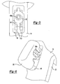
- Figure 8 illustrates the rear handle portion 20 being engaged with the front handle portion 14 and showing the sliding engagement between slide rails 70 of the rear handle portion 20 and the slide rails 44 provided on the lower surface 24b of the field case 12.
- the end cap 22 is generally semi-spherical in shape and includes a plurality of screw bosses 80 for receiving threaded fasteners 32 therethrough for mounting the end cap 22 to the field case 12 via screw bosses 30 provided on the field case 12.
- the motor 40 is received in the motor chamber 26 of the field case 12. Electrical connections to the motor 40 are provided through apertures 36 provided in the field case 12 for connection to terminal posts 82 which are mounted to the motor 40.
- the output shaft 84 of the motor 40 is drivingly connected to a gear system provided in gear case cover 16.
- the gear system can be of the multi-speed type that can be manually switched by the operator, or a single speed type.
- An impact mechanism 86 is driven by the gear system and includes an output spindle 88.
- the gear case 18 is received over top of the impact mechanism 86.
- the impact mechanism 86 is well known in the art and therefore, a detailed description thereof will be omitted.
- the gear case 18 includes a rear opening 90 for receiving the impact mechanism 86 and a front opening 92 for receiving the output spindle 88 therethrough. Threaded fasteners 29 are provided for mounting the gear case 18 and gear case cover 16 to the field housing 12.
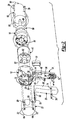
- FIG. 7 a rear view of the field case 12 and front handle portion 14 is shown with the wire system 100 illustrated in a full "wired-up" condition.
- the cord 64 is attached to the housing by a flanged rubber boot 102 with a flange 104 being received in a recess region 106 in the front handle portion 14.
- a clamp plate 108 and threaded fasteners 110 are provided for securing the cord 64 to the front handle portion 14 via the clamp bosses 60.
- the cord 64 includes two wires 112 which are connected to the switch 48 and motor 40 in a manner that is well known in the art. Additional wires 112 extending from the switch to the motor are connected to the motor in a manner that is well known in the art.
- the wires 112 extend through the opening or cavity 56 in the rear of the front handle portion 14 and between slide rails 44 of the field case 12 and along bridge 42 in the rear of field case 12.
- the bridge 42 is provided with anchor slots 116 in which wires 112 can be inserted prior to or after connection to the motor terminals.
- the rear handle portion 20 is then installed over the wires 112 to enclose the rear opening 56 in the front handle portion 14.
- the slide rails 70 of the upper cover portion 66 of rear handle portion 20 engage slide rails 44 provided on the field case 12 while the upper cover portion 66 covers the wires 112 disposed between the slide rails 44.
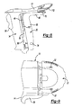
- the end cap 22 is then installed over the rear of the field case 12 and secured by fasteners 32.
- the end cap 22 covers the remaining exposed wires 112 which are connected to the motor 40.
- the end cap 22 has a step feature that engages the top rear portion of the rear handle portion 20 and secures the rear handle portion 20 to the rails on the field case 12. Installation of the end cap 22 completes the assembly of the power tool 10.
- the front handle design simplifies the wire-up of the power tool.
- the wire-up is simplified primarily because all wire-up occurs on the rear side of the handle with no need to flip the tool over to complete the wire-up.
- a soft grip surface can be applied to the rear handle portion 20 without having to alter the front handle portion 14.
Landscapes
- Engineering & Computer Science (AREA)
- Mechanical Engineering (AREA)
- Portable Power Tools In General (AREA)
Applications Claiming Priority (2)
| Application Number | Priority Date | Filing Date | Title |
|---|---|---|---|
| US10/849,983 US7077218B2 (en) | 2004-05-20 | 2004-05-20 | Motor housing and assembly process for power tool |
| EP05009800A EP1598151A3 (fr) | 2004-05-20 | 2005-05-05 | Boîtier de moteur et procédé d'assemblage pour clé à chocs |
Related Parent Applications (1)
| Application Number | Title | Priority Date | Filing Date |
|---|---|---|---|
| EP05009800.3 Division | 2005-05-05 |
Publications (2)
| Publication Number | Publication Date |
|---|---|
| EP2241413A2 true EP2241413A2 (fr) | 2010-10-20 |
| EP2241413A3 EP2241413A3 (fr) | 2010-11-03 |
Family
ID=34936153
Family Applications (4)
| Application Number | Title | Priority Date | Filing Date |
|---|---|---|---|
| EP10177999A Withdrawn EP2258519A1 (fr) | 2004-05-20 | 2005-05-05 | Boîtier de moteur pour clé à chocs |
| EP05009800A Withdrawn EP1598151A3 (fr) | 2004-05-20 | 2005-05-05 | Boîtier de moteur et procédé d'assemblage pour clé à chocs |
| EP10178001A Withdrawn EP2258520A1 (fr) | 2004-05-20 | 2005-05-05 | Procédé d'assemblage pour clé à chocs |
| EP10171919A Withdrawn EP2241413A3 (fr) | 2004-05-20 | 2005-05-05 | Boîtier de moteur et procédé d'assemblage pour clé à chocs |
Family Applications Before (3)
| Application Number | Title | Priority Date | Filing Date |
|---|---|---|---|
| EP10177999A Withdrawn EP2258519A1 (fr) | 2004-05-20 | 2005-05-05 | Boîtier de moteur pour clé à chocs |
| EP05009800A Withdrawn EP1598151A3 (fr) | 2004-05-20 | 2005-05-05 | Boîtier de moteur et procédé d'assemblage pour clé à chocs |
| EP10178001A Withdrawn EP2258520A1 (fr) | 2004-05-20 | 2005-05-05 | Procédé d'assemblage pour clé à chocs |
Country Status (4)
| Country | Link |
|---|---|
| US (2) | US7077218B2 (fr) |
| EP (4) | EP2258519A1 (fr) |
| JP (1) | JP2005329537A (fr) |
| CN (1) | CN100540233C (fr) |
Families Citing this family (58)
| Publication number | Priority date | Publication date | Assignee | Title |
|---|---|---|---|---|
| USD559059S1 (en) * | 2004-01-13 | 2008-01-08 | Black & Decker Inc. | Drill |
| USD534403S1 (en) * | 2004-01-13 | 2007-01-02 | Black & Decker Inc. | Drill |
| JP4084319B2 (ja) * | 2004-02-23 | 2008-04-30 | リョービ株式会社 | 電動工具 |
| DE102004031628A1 (de) * | 2004-06-30 | 2006-02-02 | Robert Bosch Gmbh | Vorrichtung mit einer Innenschale und einer Außenschale eines Gehäuses einer Handwerkzeugmaschine |
| DE102004036584B4 (de) * | 2004-07-28 | 2019-08-01 | Robert Bosch Gmbh | Elektrowerkzeugmaschine |
| DE102004036805A1 (de) * | 2004-07-29 | 2006-03-23 | Robert Bosch Gmbh | Elektrowerkzeug mit innerem Befestigungselement |
| DE102005037255A1 (de) * | 2005-08-08 | 2007-02-15 | Robert Bosch Gmbh | Elektrowerkzeugmaschine |
| US7261166B2 (en) * | 2005-09-16 | 2007-08-28 | Robert Bosch Gmbh | Switch for power tool |
| US7980324B2 (en) * | 2006-02-03 | 2011-07-19 | Black & Decker Inc. | Housing and gearbox for drill or driver |
| USD577973S1 (en) * | 2006-09-12 | 2008-10-07 | Black & Decker Inc. | Drill |
| USD590683S1 (en) * | 2006-09-12 | 2009-04-21 | Black & Decker Inc. | Drill |
| DE102006000543A1 (de) * | 2006-12-21 | 2008-06-26 | Hilti Ag | Handwerkzeuggerät mit einem mehrteiligen Gehäuse |
| USD593829S1 (en) * | 2007-08-23 | 2009-06-09 | Black & Decker Inc. | Driver |
| USD593830S1 (en) * | 2007-08-23 | 2009-06-09 | Black & Decker Inc. | Driver |
| USD595553S1 (en) * | 2007-08-23 | 2009-07-07 | Black & Decker Inc. | Driver |
| USD589316S1 (en) * | 2007-08-23 | 2009-03-31 | Black & Decker Inc. | Driver |
| US7762349B2 (en) | 2007-11-21 | 2010-07-27 | Black & Decker Inc. | Multi-speed drill and transmission with low gear only clutch |
| US7735575B2 (en) | 2007-11-21 | 2010-06-15 | Black & Decker Inc. | Hammer drill with hard hammer support structure |
| US7717192B2 (en) | 2007-11-21 | 2010-05-18 | Black & Decker Inc. | Multi-mode drill with mode collar |
| US7798245B2 (en) * | 2007-11-21 | 2010-09-21 | Black & Decker Inc. | Multi-mode drill with an electronic switching arrangement |
| US7770660B2 (en) * | 2007-11-21 | 2010-08-10 | Black & Decker Inc. | Mid-handle drill construction and assembly process |
| US7854274B2 (en) | 2007-11-21 | 2010-12-21 | Black & Decker Inc. | Multi-mode drill and transmission sub-assembly including a gear case cover supporting biasing |
| US7717191B2 (en) | 2007-11-21 | 2010-05-18 | Black & Decker Inc. | Multi-mode hammer drill with shift lock |
| USD592928S1 (en) * | 2008-09-17 | 2009-05-26 | Black & Decker Inc. | Corded drill |
| US8267192B2 (en) | 2009-02-24 | 2012-09-18 | Black & Decker Inc. | Ergonomic handle for power tool |
| USD609544S1 (en) | 2009-02-24 | 2010-02-09 | Black & Decker, Inc. | Drill driver |
| JP5319422B2 (ja) | 2009-06-29 | 2013-10-16 | 株式会社マキタ | モータアッセンブリの組み付け構造 |
| DE202009010557U1 (de) | 2009-08-05 | 2010-12-16 | Makita Corp., Anjo | Vormontierte Vorrichtung |
| USD617622S1 (en) | 2009-09-30 | 2010-06-15 | Black & Decker Inc. | Impact driver |
| USD626394S1 (en) | 2010-02-04 | 2010-11-02 | Black & Decker Inc. | Drill |
| USD646947S1 (en) | 2010-08-13 | 2011-10-18 | Black & Decker Inc. | Drill |
| WO2012134472A1 (fr) * | 2011-03-31 | 2012-10-04 | Ingersoll-Rand Company | Boîtier d'engrenages à verrou tournant pour outils électriques |
| US9044850B2 (en) | 2011-07-27 | 2015-06-02 | Ingersoll-Rand Company | Twist lock gear case for power tools |
| EP2691215B1 (fr) * | 2011-03-31 | 2016-11-23 | Ingersoll-Rand Company | Outils électriques portatifs pourvus de déclencheurs et leur procédé d'assemblage |
| US20140008090A1 (en) * | 2011-03-31 | 2014-01-09 | Ingersoll-Rand Company | Handheld Power Tools with Triggers and Methods for Assembling Same |
| DE102013210752A1 (de) * | 2012-11-27 | 2014-06-12 | Robert Bosch Gmbh | Handwerkzeugvorrichtung |
| EP3189940B1 (fr) * | 2012-12-25 | 2018-01-31 | Makita Corporation | Outil à impact |
| JP6090581B2 (ja) * | 2013-09-28 | 2017-03-08 | 日立工機株式会社 | 電動工具 |
| WO2016196984A1 (fr) | 2015-06-05 | 2016-12-08 | Ingersoll-Rand Company | Machines portatives à moteur à modes de fonctionnement sélectionnables par l'utilisateur |
| WO2016196918A1 (fr) | 2015-06-05 | 2016-12-08 | Ingersoll-Rand Company | Interfaces utilisateur d'outil électrique |
| CN107735223B (zh) * | 2015-06-05 | 2022-01-11 | 英格索兰工业美国公司 | 动力工具壳体 |
| WO2016196891A1 (fr) | 2015-06-05 | 2016-12-08 | Ingersoll-Rand Company | Interfaces utilisateur de machine-outil électrique |
| US11260517B2 (en) | 2015-06-05 | 2022-03-01 | Ingersoll-Rand Industrial U.S., Inc. | Power tool housings |
| US10668614B2 (en) | 2015-06-05 | 2020-06-02 | Ingersoll-Rand Industrial U.S., Inc. | Impact tools with ring gear alignment features |
| CN107635725B (zh) | 2015-06-05 | 2019-11-12 | 英古所连公司 | 用于电动工具的照明系统 |
| JP6947256B2 (ja) * | 2016-05-30 | 2021-10-13 | マックス株式会社 | 電動工具 |
| KR200486506Y1 (ko) * | 2016-07-21 | 2018-05-29 | 주식회사 아임삭 | 망치나 자석 기능을 구비하는 전동공구 보조장치 |
| KR102548258B1 (ko) * | 2016-08-25 | 2023-06-28 | 엘지전자 주식회사 | 청소기 |
| WO2018038365A1 (fr) | 2016-08-25 | 2018-03-01 | 엘지전자 주식회사 | Aspirateur |
| JP6863704B2 (ja) | 2016-10-07 | 2021-04-21 | 株式会社マキタ | 打撃工具 |
| US10875168B2 (en) | 2016-10-07 | 2020-12-29 | Makita Corporation | Power tool |
| WO2019161932A1 (fr) | 2018-02-26 | 2019-08-29 | Alfred Kärcher SE & Co. KG | Appareil portable de nettoyage de surfaces dures |
| JP7246202B2 (ja) | 2019-02-19 | 2023-03-27 | 株式会社マキタ | 震動機構付き電動工具 |
| JP7229807B2 (ja) | 2019-02-21 | 2023-02-28 | 株式会社マキタ | 電動工具 |
| JP7526012B2 (ja) * | 2020-03-10 | 2024-07-31 | 株式会社マキタ | 電動工具 |
| CN111546295A (zh) * | 2020-05-12 | 2020-08-18 | 浙江动一新能源动力科技股份有限公司 | 一种电动工具壳体及电动工具 |
| JP7149994B2 (ja) * | 2020-08-26 | 2022-10-07 | 株式会社マキタ | インパクト工具 |
| US11883941B2 (en) * | 2021-02-15 | 2024-01-30 | Makita Corporation | Hammer drill |
Family Cites Families (22)
| Publication number | Priority date | Publication date | Assignee | Title |
|---|---|---|---|---|
| US1754222A (en) * | 1928-02-13 | 1930-04-15 | Dorn Electric Tool Company Van | Electric drill |
| US2024276A (en) * | 1934-10-22 | 1935-12-17 | Desoutter Charles | Rotary tool device |
| US2383379A (en) * | 1943-12-30 | 1945-08-21 | Independent Pneumatic Tool Co | Switch mounting for electric drills |
| US2430527A (en) * | 1944-09-13 | 1947-11-11 | Independent Pneumatic Tool Co | Plastic handle securing means for drills |
| US3369615A (en) * | 1966-05-27 | 1968-02-20 | Black & Decker Mfg Co | Impact wrench |
| US3494799A (en) * | 1968-10-01 | 1970-02-10 | Black & Decker Mfg Co | Battery access handle for cordless electric device |
| DE2042012A1 (de) * | 1970-08-25 | 1972-03-02 | Bosch Gmbh Robert | Kraftwerkzeug |
| US4991472A (en) | 1988-11-04 | 1991-02-12 | James Curtis Hilliard | D.C. direct drive impact wrench |
| USD392863S (en) | 1996-11-01 | 1998-03-31 | Makita Corporation | Cordless impact driver |
| DE19703746A1 (de) | 1997-02-03 | 1998-08-06 | Scintilla Ag | Handwerkzeugmaschine |
| USD403219S (en) | 1997-07-31 | 1998-12-29 | Porter-Cable Corporation | Impact wrench |
| DE19918118B4 (de) | 1999-04-22 | 2008-04-10 | Scintilla Ag | Softgriffelement für Elektrohandwerkzeugmaschinen |
| US6536536B1 (en) * | 1999-04-29 | 2003-03-25 | Stephen F. Gass | Power tools |
| US6446734B1 (en) * | 1999-11-11 | 2002-09-10 | Black & Decker Inc. | Motor/handle housing and gear case mounting for portable power tool |
| USD437761S1 (en) | 1999-11-19 | 2001-02-20 | Makita Corporation | Rechargeable impact wrench |
| US6502648B2 (en) * | 2001-01-23 | 2003-01-07 | Black & Decker Inc. | 360 degree clutch collar |
| DE10104866A1 (de) * | 2001-02-03 | 2002-08-14 | Bosch Gmbh Robert | Handwerkzeugmaschine mit einem elektrische Komponenten aufnehmenden Handgriff |
| US6472747B2 (en) * | 2001-03-02 | 2002-10-29 | Qualcomm Incorporated | Mixed analog and digital integrated circuits |
| USD469673S1 (en) | 2001-11-30 | 2003-02-04 | Ingersoll-Rand Company | Impact wrench |
| US6719067B2 (en) | 2001-12-27 | 2004-04-13 | Taga Corporation | Insert for a plastic power tool housing |
| DE10228452A1 (de) | 2002-06-26 | 2004-01-22 | Robert Bosch Gmbh | Handgriff einer Werkzeugmaschine |
| DE10251557A1 (de) * | 2002-11-06 | 2004-05-19 | Robert Bosch Gmbh | Handwerkzeugmaschine mit einem pistolenförmigen Handgriff |
-
2004
- 2004-05-20 US US10/849,983 patent/US7077218B2/en not_active Expired - Lifetime
-
2005
- 2005-05-05 EP EP10177999A patent/EP2258519A1/fr not_active Withdrawn
- 2005-05-05 EP EP05009800A patent/EP1598151A3/fr not_active Withdrawn
- 2005-05-05 EP EP10178001A patent/EP2258520A1/fr not_active Withdrawn
- 2005-05-05 EP EP10171919A patent/EP2241413A3/fr not_active Withdrawn
- 2005-05-20 CN CNB2005100737146A patent/CN100540233C/zh not_active Expired - Fee Related
- 2005-05-20 JP JP2005147554A patent/JP2005329537A/ja not_active Withdrawn
-
2006
- 2006-05-23 US US11/439,420 patent/US7134510B2/en not_active Expired - Lifetime
Non-Patent Citations (1)
| Title |
|---|
| None |
Also Published As
| Publication number | Publication date |
|---|---|
| US20050257945A1 (en) | 2005-11-24 |
| US7077218B2 (en) | 2006-07-18 |
| CN100540233C (zh) | 2009-09-16 |
| EP2258520A1 (fr) | 2010-12-08 |
| EP2258519A1 (fr) | 2010-12-08 |
| JP2005329537A (ja) | 2005-12-02 |
| EP2241413A3 (fr) | 2010-11-03 |
| US20060208026A1 (en) | 2006-09-21 |
| US7134510B2 (en) | 2006-11-14 |
| CN1699030A (zh) | 2005-11-23 |
| EP1598151A2 (fr) | 2005-11-23 |
| EP1598151A3 (fr) | 2008-03-19 |
Similar Documents
| Publication | Publication Date | Title |
|---|---|---|
| US7077218B2 (en) | Motor housing and assembly process for power tool | |
| US7770660B2 (en) | Mid-handle drill construction and assembly process | |
| US8708063B2 (en) | Rechargeable electric tool | |
| US7786627B2 (en) | Electrical hand-held power tool with cooling of electronics | |
| CN102335895B (zh) | 具有电路板的电动工具 | |
| CN109202822B (zh) | 电动工具 | |
| CN109217505B (zh) | 电动工具 | |
| CN110957441B (zh) | 电池组及电气设备 | |
| US20120184191A1 (en) | Electric power tool, in particular a grinding or polishing machine | |
| EP2228179A1 (fr) | Outil électrique | |
| JP6701975B2 (ja) | 電動工具 | |
| US7229301B2 (en) | Motor-switch arrangement for a hand-held power tool | |
| DK1459853T3 (da) | Elektrisk håndværktöj | |
| US12597666B2 (en) | Nosecone to battery connection in power tool | |
| JP7824556B2 (ja) | 電動工具 | |
| JP7060618B2 (ja) | 電動作業機および電動作業機に電気系統を構築する方法 | |
| JP7700010B2 (ja) | 電動工具 | |
| CN111200303A (zh) | 电池组以及使用该电池组的电气设备 | |
| GB2417457A (en) | Electric tool with internal component fastening element | |
| JP7794654B2 (ja) | 打撃工具 | |
| JP7822189B2 (ja) | 打撃工具 | |
| CN110948451A (zh) | 电气设备及电池组 |
Legal Events
| Date | Code | Title | Description |
|---|---|---|---|
| PUAI | Public reference made under article 153(3) epc to a published international application that has entered the european phase |
Free format text: ORIGINAL CODE: 0009012 |
|
| PUAL | Search report despatched |
Free format text: ORIGINAL CODE: 0009013 |
|
| 17P | Request for examination filed |
Effective date: 20100804 |
|
| AC | Divisional application: reference to earlier application |
Ref document number: 1598151 Country of ref document: EP Kind code of ref document: P |
|
| AK | Designated contracting states |
Kind code of ref document: A2 Designated state(s): AT BE BG CH CY CZ DE DK EE ES FI FR GB GR HU IE IS IT LI LT LU MC NL PL PT RO SE SI SK TR |
|
| AK | Designated contracting states |
Kind code of ref document: A3 Designated state(s): AT BE BG CH CY CZ DE DK EE ES FI FR GB GR HU IE IS IT LI LT LU MC NL PL PT RO SE SI SK TR |
|
| STAA | Information on the status of an ep patent application or granted ep patent |
Free format text: STATUS: THE APPLICATION IS DEEMED TO BE WITHDRAWN |
|
| 18D | Application deemed to be withdrawn |
Effective date: 20110504 |