EP2241417B1 - Boîte à gants - Google Patents
Boîte à gants Download PDFInfo
- Publication number
- EP2241417B1 EP2241417B1 EP08863722.8A EP08863722A EP2241417B1 EP 2241417 B1 EP2241417 B1 EP 2241417B1 EP 08863722 A EP08863722 A EP 08863722A EP 2241417 B1 EP2241417 B1 EP 2241417B1
- Authority
- EP
- European Patent Office
- Prior art keywords
- glove
- box body
- main box
- viewing window
- antechamber
- Prior art date
- Legal status (The legal status is an assumption and is not a legal conclusion. Google has not performed a legal analysis and makes no representation as to the accuracy of the status listed.)
- Active
Links
Images


Classifications
-
- B—PERFORMING OPERATIONS; TRANSPORTING
- B25—HAND TOOLS; PORTABLE POWER-DRIVEN TOOLS; MANIPULATORS
- B25J—MANIPULATORS; CHAMBERS PROVIDED WITH MANIPULATION DEVICES
- B25J21/00—Chambers provided with manipulation devices
- B25J21/02—Glove-boxes, i.e. chambers in which manipulations are performed by the human hands in gloves built into the chamber walls; Gloves therefor
Definitions
- the present invention relates to a glove box and especially to a glove box with leakage shielding space, belonging to the technical field of a glove box system.
- a glove box which can be made of metals or plastics, is a typical example of such a device, including a main box body having multiple openings equipped thereon with a viewing window, an antechamber, glove ports and so on. Operators operate the materials and devices inside the box body through a glove, and the antechamber is used for transferring materials and devices into and out of the glove box.
- the glove box is normally equipped with a circulating purification system.
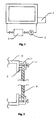
- the system comprises a blower 2 and a purification column 3.
- the purification column 3 is filled with oxygen and moisture retaining materials.
- the impurity-containing gas is blown through the purification materials by the blower 2, and the oxygen and moisture are retained.
- the purified gas is then returned to the glove box.
- Continuous circulation like that will reduce the respective contents of oxygen and moisture to an equilibrium, namely that, the rate that oxygen and moisture leak into glove box is equal to the removing rate by the purification system. So that, the purity of gas inside the glove box is decided by both of the leak rate of the glove box and the efficiency of the purification system.
- the two key technologies in a glove box system are sealing and gas purification.
- the sealing technology used in the glove box is the traditional sealing technology.
- there is one layer of sealing material (such as a sealing ring 5, a sealing strip, or a sealant) placed between two sealing surfaces.
- the inner side of the sealing material is ultra-high purity gas, and the outer side of the sealing material is air.
- Air has oxygen concentration of higher than 200,000ppm and can easily leak into the glove box through tiny gaps to greatly affect the gas purity inside the box.
- CN 2653228 discloses a vacuum glove box sealing device, comprising a stand, a transparent faceplate and an elastic sealing ring which is arranged between a fitting face of the stand and the inner surface of the transparent faceplate.
- the glove box is characterized in that a pressing bar connected with the stand by a connecting unit is arranged around the periphery of the transparent faceplate, the pressing bar is tightly pressed on the periphery of the transparent faceplate, and the fitting face of the stand is sealed with the elastic sealing ring while the elastic sealing ring is sealed with the transparent faceplate.
- a glove box comprises a main box body, a viewing window placed on the main box body, glove ports installed on the viewing window, side panels attached to the main box body, and an antechamber installed on the side panel;
- the main box body, the side panel, the glove ports and the antechamber have contact surfaces for contacting with sealing rings, characterized in that , on at least one of five interfaces, namely, between the main box body and the viewing window, between the main box body and the side panel, between the viewing window and the glove port, between the glove port and the glove, between the side panel and the antechamber, a leakage shielding space is formed.
- a drainage groove is created on any of the contact surfaces, and the sealing ring is fitted over the drainage groove, such that the leakage shielding space is formed between the drainage groove and the sealing ring.
- a drainage groove is created on any of the contact surfaces, also the sealing ring has a corresponding drainage groove, such that a leakage shielding space is formed between the drainage grooves.
- the sealing ring has a groove at each of its two contacting sides, such that, two leakage shielding spaces are formed between the grooves and the contact surfaces after the sealing ring is mounted.
- At least two sealing rings are used correspondingly on the contact surfaces, such that a leakage shielding space is formed between the sealing rings.
- a vacuum is created inside the leakage shielding space.
- flowing high purity gas, or gaseous substance harmless to materials inside the glove box and harmless to an operator outside the glove box is filled inside the leakage shielding space.
- a leakage shielding space can be formed between the main box body and the viewing window, or between the main box body and the side panel, or between the viewing window and the glove port, or between the glove port and the glove, or between the side panel and the antechamber, so as to ensure the purity in the operating space of the glove box and to effectively block the external contaminants from leaking inside due to the existence of gaps, so as to keep the moisture impurity below 1ppm and the oxygen impurity below 1ppm to maintain the degree of purity of gas.
- the glove box of the present invention by implementing the glove box of the present invention, harmful substances inside the glove box will be blocked from leaking outwards due to the existence of gaps, so as to prevent the environment outside the glove box from being polluted.
- the present invention is easy to implement, and has made improvements in this technical field.
- the glove box comprises the following key components: a main box body, a viewing window placed on the main box body, glove ports on the viewing window, side panels, and an antechamber.
- the main body box, the side panel, the glove ports and the antechamber have contact surfaces sealed with sealing rings 5.
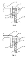
- a drainage groove is created on any of the contact surfaces, the sealing ring 5 is fitted over the drainage groove, such that the leakage shielding space 4 is formed between the drainage groove and the sealing ring 5.
- a drainage groove is created on a contact surface, also the sealing ring 5 has a corresponding drainage groove, such that a leakage shielding space 4 is formed between the two drainage grooves.
- the sealing ring 5 has a groove at each of its two contacting sides, such that, two leakage shielding spaces 4 are formed between in the grooves and the contact surfaces after the sealing ring 5 is mounted, so as to further ensure the shielding effect.
- at least two sealing rings 5 are used correspondingly on a contact surface, such that a leakage shielding space 4 is formed between the sealing rings 5.
- the leakage shielding space 4 is filled with high purity gas, and the high purity gas is forced to flow continuously inside the leakage shielding space 4.
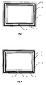
- the opening of the main box body has an inside edge 9 at its periphery, and two concentric circular sealing rings 5 are placed on the inside edge 9, the viewing window 8 is fitted over the sealing rings 5.
- the viewing window 8 is made of glass or plastic, and is securely attached, at its periphery, to the main box body by a holding strip 10 and screws 11.
- a leakage shielding space 4 can be formed between the main box body and the side panel, or between the viewing window and the glove port, or between the side panel and the antechamber.
- the connection between the main box body and the side panel, and the connection between the side panel and the antechamber can be realized by welding as done traditionally, and a relatively tight sealing effect can be obtained.
- a through hole 6 is opened to the leakage shielding space 4.
- the through hole 6 is connected to a vacuum pump to create a vacuum in the leakage shielding space 4 and to evacuate the possible contaminants leaked into the leakage shielding space 4, so as to prevent the contaminants from leaking further into the glove box.
- the opening of the main box body has an inside edge 9 at its periphery, and two concentric circular sealing rings 5 are placed on the inside edge 9, the viewing window 8 is fitted over the sealing rings 5.
- the viewing window 8 is made of glass or plastic, and is securely attached, at its periphery, to the main box body by a holding strip 10 and screws 11.
- a leakage shielding space 4 can be formed between the main box body and the side panel, or between the viewing window and the glove port, or between the side panel and the antechamber.
- two through holes 6 are opened to the leakage shielding space 4, and the two through holes are separated by a spacer 7. Moreover, one of the through holes 6 is connected to a high purity gas source to purge the leakage shielding space 4. By means of the partition by the spacer 7, the high purity gas fills the leakage shielding space 4, and is forced to flow orderly.
- the main box body has, at its interface sealed with the sealing ring 5, a drainage groove, such that a leakage shielding space 4 is formed between the drainage groove and the sealing ring 5. Furthermore, in order to create a leakage shielding space on other interfaces of the main box body, the main box body and the side panel also have drainage grooves at their contact surface sealed with the sealing rings 5, such that a leakage shielding space 4 is formed between the drainage groove and the sealing ring 5.
- the glove port may also, on its contact surface with a glove mounted thereon, have a drainage groove, such that a leakage shielding space 4 is formed between the drainage groove and the glove.
- the side panel and the antechamber may also have drainage grooves on their contact surfaces sealed with the sealing rings 5, such that a leakage shielding space 4 is formed between the drainage groove and the sealing ring 5.
- a drainage groove is placed on the viewing window 8, also a leakage shielding space 4 can be formed between the drainage groove and the sealing ring 5.
- the main box body and the viewing window 8 are sealed with the sealing ring 5 at their contact surface, where a drainage groove is provided on the main body contact surface and the sealing ring 5 has a corresponding drainage groove, such that a leakage shielding space 4 is formed between the two drainage grooves.
- the assembling of other parts of the glove box is the same as that in Embodiment 3, and there is no need to go into details here.
- a leakage shielding space can be formed between the main box body and the viewing window 8, or between the main box body and the side panel, or between the viewing window 8 and the glove port, or between the glove port and the glove, or between the side panel and the antechamber, so as to ensure the purity in the operating space of the glove box and to effectively block the external contaminants from leaking inside due to the existence of gaps, so as to keep the moisture impurity below 1ppm and the oxygen impurity below 1ppm.
Landscapes
- Engineering & Computer Science (AREA)
- Robotics (AREA)
- Mechanical Engineering (AREA)
- Manipulator (AREA)
- Devices For Use In Laboratory Experiments (AREA)
Claims (6)
- Boîte à gants comprenant un corps de boîte principal, une fenêtre de vision (8) placée sur le corps de boîte principal, des orifices de gants installés dans la fenêtre de vision (8), des panneaux latéraux fixés au corps de boîte principal et une antichambre (1) installée sur le panneau latéral, le corps de boîte principal, les panneaux latéraux, l'orifice de gants et l'antichambre (1) ayant des surfaces de contact agencées pour venir en contact avec une ou plusieurs bagues d'étanchéité (5),
caractérisée en ce que, sur au moins une de cinq interfaces, incluant entre le corps de boîte principal et la fenêtre de vision, entre le corps de boîte principal et le panneau latéral, entre la fenêtre de vision et l'orifice de gants, entre l'orifice de gants et les gants et entre le panneau latéral et l'antichambre, un espace de protection contre une fuite (4) est formé, où
une rainure de drainage est réalisée sur une ou plusieurs des surfaces de contact, et une ou plusieurs bagues d'étanchéité précités (5) sont ajustées sur la rainure de drainage, de sorte que l'espace de protection contre une fuite (4) est formé entre la rainure de drainage et une ou plusieurs bagues d'étanchéité précitées. - Boîte à gants comprenant un corps de boîte principal, une fenêtre de vision (8) placée sur le corps de boîte principal, des orifices de gants installés sur la fenêtre de vision (8), des panneaux latéraux fixés au corps de boîte principal et une antichambre (1) installée sur le panneau latéral, le corps de boîte principal, les panneaux latéraux, l'orifice de gants et l'antichambre (1) ayant des surfaces de contact agencées pour venir en contact avec une ou plusieurs bagues d'étanchéité (5),
caractérisée en ce que, sur au moins une des cinq interfaces, incluant entre le corps de boîte principal et la fenêtre de vision, entre le corps de boîte principal et le panneau latéral, entre la fenêtre de vision et l'orifice de gants, entre l'orifice de gants et les gants, et entre le panneau latéral et l'antichambre, un espace de protection contre une fuite (4) est formé, où
une rainure de drainage est réalisée sur une ou plusieurs des surfaces de contact, de même une ou plusieurs bagues d'étanchéité (5) ont une rainure de drainage correspondante, de sorte qu'un espace de protection contre une fuite (4) est formé entre les rainures de drainage. - Boîte à gants comprenant un corps de boîte principal, une fenêtre de vision (8) placée sur le corps de boîte principal, des orifices de gants installés sur la fenêtre de vision (8), des panneaux latéraux fixés au corps de boîte principal et une antichambre (1) installée sur le panneau latéral, le corps de boîte principal, les panneaux latéraux, l'orifice de gants et l'antichambre (1) ayant des surfaces de contact agencées pour venir en contact avec une ou plusieurs bagues d'étanchéité (5),
caractérisée en ce que, sur au moins une de cinq interfaces, incluant entre le corps de boîte principal et la fenêtre de vision, entre le corps de boîte principal et le panneau latéral, entre la fenêtre de vision et l'orifice de gants, entre l'orifice de gants et les gants et entre le panneau latéral et l'antichambre, un espace de protection contre une fuite (4) est formé, où
au moins deux bagues d'étanchéité (5) sont placées d'une manière correspondante sur les surfaces de contact de sorte qu'un espace de protection contre une fuite (4) est formé entre les au moins deux bagues d'étanchéité. - Boîte à gants selon l'une quelconque des revendications 1, 2 ou 3, caractérisé en ce que la bague d'étanchéité (5) présente une rainure dans chacun de ses deux côtés de contact de sorte que deux espaces de protection contre une fuite (4) sont formés entre la bague d'étanchéité (5) et les surfaces de contact après que la bague d'étanchéité a été montée.
- Boîte à gants selon l'une quelconque des revendications 1, 2 ou 3, caractérisée en ce qu'un vide est créé à l'intérieur de l'espace de protection contre une fuite (4).
- Boîte à gants selon l'une quelconque des revendications 1, 2 ou 3, caractérisée en ce que l'espace de protection contre une fuite (4) est rempli d'un gaz coulant de pureté élevée.
Applications Claiming Priority (2)
| Application Number | Priority Date | Filing Date | Title |
|---|---|---|---|
| CN2007101915012A CN101456185B (zh) | 2007-12-12 | 2007-12-12 | 手套箱 |
| PCT/CN2008/001891 WO2009079908A1 (fr) | 2007-12-12 | 2008-11-20 | Boîte à gants |
Publications (3)
| Publication Number | Publication Date |
|---|---|
| EP2241417A1 EP2241417A1 (fr) | 2010-10-20 |
| EP2241417A4 EP2241417A4 (fr) | 2011-04-06 |
| EP2241417B1 true EP2241417B1 (fr) | 2014-05-21 |
Family
ID=40767447
Family Applications (1)
| Application Number | Title | Priority Date | Filing Date |
|---|---|---|---|
| EP08863722.8A Active EP2241417B1 (fr) | 2007-12-12 | 2008-11-20 | Boîte à gants |
Country Status (6)
| Country | Link |
|---|---|
| US (1) | US8579387B2 (fr) |
| EP (1) | EP2241417B1 (fr) |
| JP (1) | JP3165479U (fr) |
| CN (1) | CN101456185B (fr) |
| RU (1) | RU105853U1 (fr) |
| WO (1) | WO2009079908A1 (fr) |
Families Citing this family (18)
| Publication number | Priority date | Publication date | Assignee | Title |
|---|---|---|---|---|
| CN101612624B (zh) * | 2009-07-21 | 2011-12-07 | 中国电子科技集团公司第十三研究所 | 一种能防止产生二次污染的氮气保护操作箱 |
| CN101844266B (zh) * | 2010-04-26 | 2012-06-06 | 南京三乐电子信息产业集团有限公司 | 手套箱保护氩弧焊方法 |
| CN102320045A (zh) * | 2011-05-24 | 2012-01-18 | 徐东升 | 一种防尘袋 |
| FR2984790B1 (fr) * | 2011-12-22 | 2014-02-21 | Areva Nc | Dispositif de manipulation d'objets en boites a gants |
| FR2984791B1 (fr) * | 2011-12-23 | 2014-02-21 | Getinge La Calhene | Installation comportant une boite a gants et un dispositif de changement de gant integrant un suivi du changement des gants |
| CN103506097A (zh) * | 2012-06-25 | 2014-01-15 | 威格高纯气体设备科技(苏州工业园区)有限公司 | 一种手套箱可再生有机溶剂吸附装置 |
| US20140261802A1 (en) * | 2013-03-13 | 2014-09-18 | Becquerel & Sievert Co., Ltd. | Vacuum isolation device |
| US10443458B2 (en) * | 2014-05-14 | 2019-10-15 | Ford Global Technologies, Llc | Engine assembly with passageway for reducing oil leakage |
| FR3021076B1 (fr) * | 2014-05-19 | 2017-06-02 | Commissariat Energie Atomique | Barrette de montage d'un panneau par serrage sur un cadre porteur |
| CN104016134B (zh) * | 2014-06-12 | 2016-06-01 | 泰山医学院 | 一种烧结钕铁硼粉料用的真空输送设备 |
| CN104139893B (zh) * | 2014-07-11 | 2016-02-03 | 东南大学 | 一种超洁净真空部件包装储存方法 |
| CN106848098A (zh) * | 2017-02-21 | 2017-06-13 | 深圳市华星光电技术有限公司 | Oled封装手套箱 |
| CN107863170B (zh) * | 2017-10-27 | 2020-03-17 | 中核四0四有限公司 | Mox芯块制备工艺辐射防护方法 |
| US10343293B1 (en) | 2017-12-20 | 2019-07-09 | Troy Taylor | Portable enclosure for hazardous processing |
| CN110450195A (zh) * | 2019-09-06 | 2019-11-15 | 威格气体纯化科技(苏州)股份有限公司 | 气压调节室及具有其的密封箱 |
| CN110450196A (zh) * | 2019-09-06 | 2019-11-15 | 威格气体纯化科技(苏州)股份有限公司 | 检修门及具有其的密封箱 |
| CN112072153B (zh) * | 2020-07-23 | 2021-09-07 | 安徽正熹标王新能源有限公司 | 一种电池生产用防护装置 |
| CN114165144B (zh) * | 2021-12-08 | 2024-05-07 | 浙江立宇设备成套有限公司 | 高密封窥视窗 |
Family Cites Families (26)
| Publication number | Priority date | Publication date | Assignee | Title |
|---|---|---|---|---|
| US3124852A (en) * | 1964-03-17 | Inflatable seal connection | ||
| US2527084A (en) * | 1946-11-01 | 1950-10-24 | Maytag Co | Refrigerator closure with hydraulic seal |
| US3050791A (en) * | 1958-03-31 | 1962-08-28 | Univ Notre Dame Du Lac | Sealed door for a compartment having a controlled environment |
| US3088627A (en) * | 1961-03-08 | 1963-05-07 | Kewaunee Mfg Company | Window sealing structure |
| FR1393401A (fr) * | 1964-01-31 | 1965-03-26 | Equip Moderne Ind Par Applic D | Joint d'étanchéité et structures munies de ce joint |
| US3694962A (en) * | 1970-04-27 | 1972-10-03 | Sybron Corp | Sliding door sterilizer with power actuated seal |
| US3831950A (en) * | 1971-11-10 | 1974-08-27 | Chicago Bridge & Iron Co | Gasket for closure seal |
| US4010588A (en) * | 1973-10-19 | 1977-03-08 | Central Research Laboratories, Inc. | Sealing device |
| US4089571A (en) * | 1976-04-08 | 1978-05-16 | Landy Jerome J | Glove port and insert |
| US4111753A (en) * | 1976-06-07 | 1978-09-05 | National Appliance Company | Controlled atmosphere apparatus and method of transferring specimens to same |
| JPS562600A (en) * | 1979-06-21 | 1981-01-12 | Hitachi Cable | Exchanging port structure of operation member in shielding box |
| US4469335A (en) * | 1982-07-22 | 1984-09-04 | American Sterilizer Company | Sealing apparatus with sealing device operable under pressure differential established thereacross |
| DE4422419A1 (de) * | 1994-06-29 | 1996-01-04 | Patent Treuhand Ges Fuer Elektrische Gluehlampen Mbh | Glove-Box |
| CN2263573Y (zh) * | 1996-09-10 | 1997-10-01 | 中国科学院空间科学与应用研究中心 | 一种单纯注气与放气式无污染手套箱 |
| US5892200A (en) * | 1996-09-19 | 1999-04-06 | The Boc Group, Inc. | Transfer port system |
| CN2294108Y (zh) * | 1997-05-23 | 1998-10-14 | 西南交通大学 | 一种真空配料装置 |
| US5950642A (en) * | 1997-11-12 | 1999-09-14 | Porter Company/Mechanical Contractors | Clean connection and sampling apparatus and method |
| JP3002966B2 (ja) * | 1998-02-10 | 2000-01-24 | 第一電子工業株式会社 | 気密アダプタ及びその交換方法 |
| US6974197B1 (en) * | 2001-02-06 | 2005-12-13 | The United States Of America As Represented By The Secretary Of The Army | Portable glovebox and filtration system |
| DE10208513A1 (de) * | 2002-02-27 | 2003-09-11 | Bosch Gmbh Robert | Handhabungseinrichtung in einer ein geschlossenes Gehäuse aufweisenden Behandlungsvorrichtung |
| CN2534123Y (zh) * | 2002-03-12 | 2003-02-05 | 南京大学仪器厂 | 真空手套箱 |
| FR2855994A1 (fr) * | 2003-06-13 | 2004-12-17 | Snmt Ind | Dispositif d'isolation d'un milieu d'intervention contamine |
| FR2856328B1 (fr) * | 2003-06-23 | 2006-06-23 | Calhene | Dispositif de montage d'un gant sur une paroi d'isolateur |
| CN2653228Y (zh) * | 2003-09-29 | 2004-11-03 | 成都德力斯实业有限公司 | 真空手套箱密封装置 |
| US7780248B2 (en) * | 2005-07-19 | 2010-08-24 | Merrick & Company | Glovebox for a double wall containment module |
| CN201124417Y (zh) * | 2007-12-12 | 2008-10-01 | 张德龙 | 手套箱 |
-
2007
- 2007-12-12 CN CN2007101915012A patent/CN101456185B/zh active Active
-
2008
- 2008-11-20 EP EP08863722.8A patent/EP2241417B1/fr active Active
- 2008-11-20 RU RU2010128156/02U patent/RU105853U1/ru active
- 2008-11-20 US US12/746,471 patent/US8579387B2/en active Active
- 2008-11-20 JP JP2010600053U patent/JP3165479U/ja not_active Expired - Lifetime
- 2008-11-20 WO PCT/CN2008/001891 patent/WO2009079908A1/fr not_active Ceased
Also Published As
| Publication number | Publication date |
|---|---|
| CN101456185B (zh) | 2012-02-01 |
| WO2009079908A1 (fr) | 2009-07-02 |
| RU105853U1 (ru) | 2011-06-27 |
| CN101456185A (zh) | 2009-06-17 |
| US8579387B2 (en) | 2013-11-12 |
| JP3165479U (ja) | 2011-01-27 |
| US20100259138A1 (en) | 2010-10-14 |
| EP2241417A4 (fr) | 2011-04-06 |
| EP2241417A1 (fr) | 2010-10-20 |
Similar Documents
| Publication | Publication Date | Title |
|---|---|---|
| EP2241417B1 (fr) | Boîte à gants | |
| JP6495170B2 (ja) | 厚い断熱ガラス窓ユニットを収容するように設計された窓枠内に真空断熱ガラス窓ユニットを設置するためのスペーサーシステム | |
| CN100528785C (zh) | 玻璃嵌板及其制造方法 | |
| JP6343283B2 (ja) | 厚い断熱ガラス窓ユニットを収容するように設計された窓枠内に真空断熱ガラス窓ユニットを設置するためのスペーサーシステム | |
| CN100383918C (zh) | 门阀装置、处理系统及密封部件的更换方法 | |
| JP3883809B2 (ja) | ガラスチャンバを減圧する方法と装置 | |
| WO2006077599A3 (fr) | Panneau d'isolation thermique sous vide | |
| CN201124417Y (zh) | 手套箱 | |
| JPWO2018062069A1 (ja) | ガラスパネルユニットの製造方法、およびガラス窓の製造方法 | |
| US11187028B2 (en) | Filling and sealing device and method for an insulated glass unit | |
| EP3521258B1 (fr) | Procédé de production d'unité de panneau de verre | |
| CN211164050U (zh) | 检修门及具有其的密封箱 | |
| CN211137225U (zh) | 一种真空手套箱装置 | |
| CN217354123U (zh) | 一种填充氩气的高气密性中空玻璃 | |
| CN106848098A (zh) | Oled封装手套箱 | |
| CN213918361U (zh) | 多层玻璃防尘手套箱 | |
| KR101473826B1 (ko) | 기판회전 진공장치 | |
| CN112140147A (zh) | 多层玻璃防尘手套箱 | |
| CN204690099U (zh) | 真空室组件 | |
| US20170313616A1 (en) | Energy-saving plate and method for manufacturing the same | |
| JP3683893B2 (ja) | 液晶表示パネルの製造方法および液晶表示パネルの製造装置 | |
| JPH11109645A (ja) | 密着式露光装置のマスク密着方法 | |
| CN210132834U (zh) | 一种Low-E真空复合中空玻璃 | |
| CN110450196A (zh) | 检修门及具有其的密封箱 | |
| TW201736314A (zh) | 玻璃平板單元及具有該玻璃平板單元之門窗 |
Legal Events
| Date | Code | Title | Description |
|---|---|---|---|
| PUAI | Public reference made under article 153(3) epc to a published international application that has entered the european phase |
Free format text: ORIGINAL CODE: 0009012 |
|
| 17P | Request for examination filed |
Effective date: 20100716 |
|
| AK | Designated contracting states |
Kind code of ref document: A1 Designated state(s): AT BE BG CH CY CZ DE DK EE ES FI FR GB GR HR HU IE IS IT LI LT LU LV MC MT NL NO PL PT RO SE SI SK TR |
|
| AX | Request for extension of the european patent |
Extension state: AL BA MK RS |
|
| DAX | Request for extension of the european patent (deleted) | ||
| A4 | Supplementary search report drawn up and despatched |
Effective date: 20110308 |
|
| 17Q | First examination report despatched |
Effective date: 20111108 |
|
| RAP1 | Party data changed (applicant data changed or rights of an application transferred) |
Owner name: VIGOR GAS SEPARATION EQUIPMENT TECHNOLOGIES (SIP) |
|
| RIN1 | Information on inventor provided before grant (corrected) |
Inventor name: VIGOR GAS SEPARATION EQUIPMENT TECHNOLOGIES (SIP) |
|
| GRAP | Despatch of communication of intention to grant a patent |
Free format text: ORIGINAL CODE: EPIDOSNIGR1 |
|
| INTG | Intention to grant announced |
Effective date: 20131219 |
|
| GRAS | Grant fee paid |
Free format text: ORIGINAL CODE: EPIDOSNIGR3 |
|
| GRAA | (expected) grant |
Free format text: ORIGINAL CODE: 0009210 |
|
| RIN1 | Information on inventor provided before grant (corrected) |
Inventor name: ZHANG, DELONG |
|
| AK | Designated contracting states |
Kind code of ref document: B1 Designated state(s): AT BE BG CH CY CZ DE DK EE ES FI FR GB GR HR HU IE IS IT LI LT LU LV MC MT NL NO PL PT RO SE SI SK TR |
|
| REG | Reference to a national code |
Ref country code: GB Ref legal event code: FG4D |
|
| REG | Reference to a national code |
Ref country code: CH Ref legal event code: EP |
|
| REG | Reference to a national code |
Ref country code: AT Ref legal event code: REF Ref document number: 669370 Country of ref document: AT Kind code of ref document: T Effective date: 20140615 |
|
| REG | Reference to a national code |
Ref country code: IE Ref legal event code: FG4D |
|
| REG | Reference to a national code |
Ref country code: DE Ref legal event code: R096 Ref document number: 602008032464 Country of ref document: DE Effective date: 20140710 |
|
| REG | Reference to a national code |
Ref country code: NL Ref legal event code: VDEP Effective date: 20140521 Ref country code: AT Ref legal event code: MK05 Ref document number: 669370 Country of ref document: AT Kind code of ref document: T Effective date: 20140521 |
|
| REG | Reference to a national code |
Ref country code: LT Ref legal event code: MG4D |
|
| PG25 | Lapsed in a contracting state [announced via postgrant information from national office to epo] |
Ref country code: FI Free format text: LAPSE BECAUSE OF FAILURE TO SUBMIT A TRANSLATION OF THE DESCRIPTION OR TO PAY THE FEE WITHIN THE PRESCRIBED TIME-LIMIT Effective date: 20140521 Ref country code: NO Free format text: LAPSE BECAUSE OF FAILURE TO SUBMIT A TRANSLATION OF THE DESCRIPTION OR TO PAY THE FEE WITHIN THE PRESCRIBED TIME-LIMIT Effective date: 20140821 Ref country code: IS Free format text: LAPSE BECAUSE OF FAILURE TO SUBMIT A TRANSLATION OF THE DESCRIPTION OR TO PAY THE FEE WITHIN THE PRESCRIBED TIME-LIMIT Effective date: 20140921 Ref country code: LT Free format text: LAPSE BECAUSE OF FAILURE TO SUBMIT A TRANSLATION OF THE DESCRIPTION OR TO PAY THE FEE WITHIN THE PRESCRIBED TIME-LIMIT Effective date: 20140521 Ref country code: GR Free format text: LAPSE BECAUSE OF FAILURE TO SUBMIT A TRANSLATION OF THE DESCRIPTION OR TO PAY THE FEE WITHIN THE PRESCRIBED TIME-LIMIT Effective date: 20140822 |
|
| PG25 | Lapsed in a contracting state [announced via postgrant information from national office to epo] |
Ref country code: PL Free format text: LAPSE BECAUSE OF FAILURE TO SUBMIT A TRANSLATION OF THE DESCRIPTION OR TO PAY THE FEE WITHIN THE PRESCRIBED TIME-LIMIT Effective date: 20140521 Ref country code: ES Free format text: LAPSE BECAUSE OF FAILURE TO SUBMIT A TRANSLATION OF THE DESCRIPTION OR TO PAY THE FEE WITHIN THE PRESCRIBED TIME-LIMIT Effective date: 20140521 Ref country code: AT Free format text: LAPSE BECAUSE OF FAILURE TO SUBMIT A TRANSLATION OF THE DESCRIPTION OR TO PAY THE FEE WITHIN THE PRESCRIBED TIME-LIMIT Effective date: 20140521 Ref country code: HR Free format text: LAPSE BECAUSE OF FAILURE TO SUBMIT A TRANSLATION OF THE DESCRIPTION OR TO PAY THE FEE WITHIN THE PRESCRIBED TIME-LIMIT Effective date: 20140521 Ref country code: SE Free format text: LAPSE BECAUSE OF FAILURE TO SUBMIT A TRANSLATION OF THE DESCRIPTION OR TO PAY THE FEE WITHIN THE PRESCRIBED TIME-LIMIT Effective date: 20140521 Ref country code: LV Free format text: LAPSE BECAUSE OF FAILURE TO SUBMIT A TRANSLATION OF THE DESCRIPTION OR TO PAY THE FEE WITHIN THE PRESCRIBED TIME-LIMIT Effective date: 20140521 |
|
| PG25 | Lapsed in a contracting state [announced via postgrant information from national office to epo] |
Ref country code: PT Free format text: LAPSE BECAUSE OF FAILURE TO SUBMIT A TRANSLATION OF THE DESCRIPTION OR TO PAY THE FEE WITHIN THE PRESCRIBED TIME-LIMIT Effective date: 20140922 |
|
| PG25 | Lapsed in a contracting state [announced via postgrant information from national office to epo] |
Ref country code: EE Free format text: LAPSE BECAUSE OF FAILURE TO SUBMIT A TRANSLATION OF THE DESCRIPTION OR TO PAY THE FEE WITHIN THE PRESCRIBED TIME-LIMIT Effective date: 20140521 Ref country code: RO Free format text: LAPSE BECAUSE OF FAILURE TO SUBMIT A TRANSLATION OF THE DESCRIPTION OR TO PAY THE FEE WITHIN THE PRESCRIBED TIME-LIMIT Effective date: 20140521 Ref country code: DK Free format text: LAPSE BECAUSE OF FAILURE TO SUBMIT A TRANSLATION OF THE DESCRIPTION OR TO PAY THE FEE WITHIN THE PRESCRIBED TIME-LIMIT Effective date: 20140521 Ref country code: CZ Free format text: LAPSE BECAUSE OF FAILURE TO SUBMIT A TRANSLATION OF THE DESCRIPTION OR TO PAY THE FEE WITHIN THE PRESCRIBED TIME-LIMIT Effective date: 20140521 Ref country code: SK Free format text: LAPSE BECAUSE OF FAILURE TO SUBMIT A TRANSLATION OF THE DESCRIPTION OR TO PAY THE FEE WITHIN THE PRESCRIBED TIME-LIMIT Effective date: 20140521 Ref country code: BE Free format text: LAPSE BECAUSE OF FAILURE TO SUBMIT A TRANSLATION OF THE DESCRIPTION OR TO PAY THE FEE WITHIN THE PRESCRIBED TIME-LIMIT Effective date: 20140521 |
|
| REG | Reference to a national code |
Ref country code: DE Ref legal event code: R097 Ref document number: 602008032464 Country of ref document: DE |
|
| PG25 | Lapsed in a contracting state [announced via postgrant information from national office to epo] |
Ref country code: NL Free format text: LAPSE BECAUSE OF FAILURE TO SUBMIT A TRANSLATION OF THE DESCRIPTION OR TO PAY THE FEE WITHIN THE PRESCRIBED TIME-LIMIT Effective date: 20140521 |
|
| PLBE | No opposition filed within time limit |
Free format text: ORIGINAL CODE: 0009261 |
|
| STAA | Information on the status of an ep patent application or granted ep patent |
Free format text: STATUS: NO OPPOSITION FILED WITHIN TIME LIMIT |
|
| REG | Reference to a national code |
Ref country code: DE Ref legal event code: R082 Ref document number: 602008032464 Country of ref document: DE Representative=s name: HASELTINE LAKE LLP, DE |
|
| 26N | No opposition filed |
Effective date: 20150224 |
|
| PG25 | Lapsed in a contracting state [announced via postgrant information from national office to epo] |
Ref country code: IT Free format text: LAPSE BECAUSE OF FAILURE TO SUBMIT A TRANSLATION OF THE DESCRIPTION OR TO PAY THE FEE WITHIN THE PRESCRIBED TIME-LIMIT Effective date: 20140521 |
|
| REG | Reference to a national code |
Ref country code: DE Ref legal event code: R082 Ref document number: 602008032464 Country of ref document: DE Representative=s name: HASELTINE LAKE LLP, DE Effective date: 20150423 Ref country code: DE Ref legal event code: R081 Ref document number: 602008032464 Country of ref document: DE Owner name: VIGOR GAS PURIFICATION TECHNOLOGIES (SUZHOU) C, CN Free format text: FORMER OWNER: VIGOR GAS SEPARATION EQUIPMENT TECHNOLOGIES (SIP) CO., LTD., SUZHOU, JIANGSU, CN Effective date: 20150423 Ref country code: DE Ref legal event code: R097 Ref document number: 602008032464 Country of ref document: DE Effective date: 20150224 |
|
| PG25 | Lapsed in a contracting state [announced via postgrant information from national office to epo] |
Ref country code: LU Free format text: LAPSE BECAUSE OF FAILURE TO SUBMIT A TRANSLATION OF THE DESCRIPTION OR TO PAY THE FEE WITHIN THE PRESCRIBED TIME-LIMIT Effective date: 20141120 Ref country code: MC Free format text: LAPSE BECAUSE OF FAILURE TO SUBMIT A TRANSLATION OF THE DESCRIPTION OR TO PAY THE FEE WITHIN THE PRESCRIBED TIME-LIMIT Effective date: 20140521 |
|
| REG | Reference to a national code |
Ref country code: CH Ref legal event code: PL |
|
| PG25 | Lapsed in a contracting state [announced via postgrant information from national office to epo] |
Ref country code: LI Free format text: LAPSE BECAUSE OF NON-PAYMENT OF DUE FEES Effective date: 20141130 Ref country code: CH Free format text: LAPSE BECAUSE OF NON-PAYMENT OF DUE FEES Effective date: 20141130 Ref country code: SI Free format text: LAPSE BECAUSE OF FAILURE TO SUBMIT A TRANSLATION OF THE DESCRIPTION OR TO PAY THE FEE WITHIN THE PRESCRIBED TIME-LIMIT Effective date: 20140521 |
|
| REG | Reference to a national code |
Ref country code: FR Ref legal event code: CD Owner name: VIGOR GAS PURIFICATION TECHNOLOGIES (SUZHOU) C, CN Effective date: 20150708 Ref country code: FR Ref legal event code: CA Effective date: 20150708 |
|
| REG | Reference to a national code |
Ref country code: IE Ref legal event code: MM4A |
|
| PG25 | Lapsed in a contracting state [announced via postgrant information from national office to epo] |
Ref country code: IE Free format text: LAPSE BECAUSE OF NON-PAYMENT OF DUE FEES Effective date: 20141120 |
|
| REG | Reference to a national code |
Ref country code: FR Ref legal event code: PLFP Year of fee payment: 8 |
|
| PG25 | Lapsed in a contracting state [announced via postgrant information from national office to epo] |
Ref country code: BG Free format text: LAPSE BECAUSE OF FAILURE TO SUBMIT A TRANSLATION OF THE DESCRIPTION OR TO PAY THE FEE WITHIN THE PRESCRIBED TIME-LIMIT Effective date: 20140521 |
|
| PG25 | Lapsed in a contracting state [announced via postgrant information from national office to epo] |
Ref country code: CY Free format text: LAPSE BECAUSE OF FAILURE TO SUBMIT A TRANSLATION OF THE DESCRIPTION OR TO PAY THE FEE WITHIN THE PRESCRIBED TIME-LIMIT Effective date: 20140521 |
|
| PG25 | Lapsed in a contracting state [announced via postgrant information from national office to epo] |
Ref country code: HU Free format text: LAPSE BECAUSE OF FAILURE TO SUBMIT A TRANSLATION OF THE DESCRIPTION OR TO PAY THE FEE WITHIN THE PRESCRIBED TIME-LIMIT; INVALID AB INITIO Effective date: 20081120 Ref country code: MT Free format text: LAPSE BECAUSE OF FAILURE TO SUBMIT A TRANSLATION OF THE DESCRIPTION OR TO PAY THE FEE WITHIN THE PRESCRIBED TIME-LIMIT Effective date: 20140521 Ref country code: TR Free format text: LAPSE BECAUSE OF FAILURE TO SUBMIT A TRANSLATION OF THE DESCRIPTION OR TO PAY THE FEE WITHIN THE PRESCRIBED TIME-LIMIT Effective date: 20140521 |
|
| REG | Reference to a national code |
Ref country code: FR Ref legal event code: PLFP Year of fee payment: 9 |
|
| REG | Reference to a national code |
Ref country code: FR Ref legal event code: PLFP Year of fee payment: 10 |
|
| REG | Reference to a national code |
Ref country code: DE Ref legal event code: R082 Ref document number: 602008032464 Country of ref document: DE Representative=s name: HL KEMPNER PATENTANWAELTE, SOLICITORS (ENGLAND, DE Ref country code: DE Ref legal event code: R082 Ref document number: 602008032464 Country of ref document: DE Representative=s name: HL KEMPNER PATENTANWALT, RECHTSANWALT, SOLICIT, DE Ref country code: DE Ref legal event code: R082 Ref document number: 602008032464 Country of ref document: DE Representative=s name: HL KEMPNER PARTG MBB, DE |
|
| P01 | Opt-out of the competence of the unified patent court (upc) registered |
Effective date: 20230530 |
|
| PGFP | Annual fee paid to national office [announced via postgrant information from national office to epo] |
Ref country code: DE Payment date: 20251118 Year of fee payment: 18 |
|
| PGFP | Annual fee paid to national office [announced via postgrant information from national office to epo] |
Ref country code: GB Payment date: 20251104 Year of fee payment: 18 |
|
| PGFP | Annual fee paid to national office [announced via postgrant information from national office to epo] |
Ref country code: FR Payment date: 20251103 Year of fee payment: 18 |