EP2241421A1 - Vorrichtung zum Portionieren von Lebensmitteln - Google Patents
Vorrichtung zum Portionieren von Lebensmitteln Download PDFInfo
- Publication number
- EP2241421A1 EP2241421A1 EP20100006821 EP10006821A EP2241421A1 EP 2241421 A1 EP2241421 A1 EP 2241421A1 EP 20100006821 EP20100006821 EP 20100006821 EP 10006821 A EP10006821 A EP 10006821A EP 2241421 A1 EP2241421 A1 EP 2241421A1
- Authority
- EP
- European Patent Office
- Prior art keywords
- portioning
- chamber
- press
- plate
- pressing
- Prior art date
- Legal status (The legal status is an assumption and is not a legal conclusion. Google has not performed a legal analysis and makes no representation as to the accuracy of the status listed.)
- Granted
Links
Images


Classifications
-
- B—PERFORMING OPERATIONS; TRANSPORTING
- B26—HAND CUTTING TOOLS; CUTTING; SEVERING
- B26D—CUTTING; DETAILS COMMON TO MACHINES FOR PERFORATING, PUNCHING, CUTTING-OUT, STAMPING-OUT OR SEVERING
- B26D7/00—Details of apparatus for cutting, cutting-out, stamping-out, punching, perforating, or severing by means other than cutting
- B26D7/01—Means for holding or positioning work
- B26D7/02—Means for holding or positioning work with clamping means
-
- B—PERFORMING OPERATIONS; TRANSPORTING
- B26—HAND CUTTING TOOLS; CUTTING; SEVERING
- B26D—CUTTING; DETAILS COMMON TO MACHINES FOR PERFORATING, PUNCHING, CUTTING-OUT, STAMPING-OUT OR SEVERING
- B26D2210/00—Machines or methods used for cutting special materials
- B26D2210/02—Machines or methods used for cutting special materials for cutting food products, e.g. food slicers
- B26D2210/04—Machines or methods used for cutting special materials for cutting food products, e.g. food slicers controlling the volume by pressing the food product, e.g. meat to a predetermined shape before cutting
-
- B—PERFORMING OPERATIONS; TRANSPORTING
- B26—HAND CUTTING TOOLS; CUTTING; SEVERING
- B26D—CUTTING; DETAILS COMMON TO MACHINES FOR PERFORATING, PUNCHING, CUTTING-OUT, STAMPING-OUT OR SEVERING
- B26D7/00—Details of apparatus for cutting, cutting-out, stamping-out, punching, perforating, or severing by means other than cutting
- B26D7/18—Means for removing cut-out material or waste
- B26D7/1818—Means for removing cut-out material or waste by pushing out
-
- Y—GENERAL TAGGING OF NEW TECHNOLOGICAL DEVELOPMENTS; GENERAL TAGGING OF CROSS-SECTIONAL TECHNOLOGIES SPANNING OVER SEVERAL SECTIONS OF THE IPC; TECHNICAL SUBJECTS COVERED BY FORMER USPC CROSS-REFERENCE ART COLLECTIONS [XRACs] AND DIGESTS
- Y10—TECHNICAL SUBJECTS COVERED BY FORMER USPC
- Y10T—TECHNICAL SUBJECTS COVERED BY FORMER US CLASSIFICATION
- Y10T83/00—Cutting
- Y10T83/202—With product handling means
Definitions
- the invention relates to a device for portioning food, in particular meat.
- Such devices are used to cut food into portions, for example in the form of slices, the same weight and / or thickness.
- the foods include, for example, fresh meat, sausage, ham, cheese, vegetables or baked goods.
- Known devices for slicing sausage or cheese are also referred to as slicers. Sausage or cheese differs from freshly grown meat because of its consistency in that the corresponding loaves have a solid shape with a volume determined by the production.
- the slicers are therefore equipped with a device for holding the loaves during slicing of the slices.
- pieces of fresh grown meat do not have a solid shape or volume, unless frozen or frozen. For portioning such pieces of meat it is therefore not enough to keep the pieces of meat as in known slicers.
- Portioning devices therefore have a pressing chamber in which the piece of meat is first compressed. After completion of the pressing process, the volume which fills the piece of meat is known. This is used during the subsequent portioning.
- Portioning devices for freshly grown meat are used, for example, in commercial kitchens, in the production of compiled and pre-packaged menus and machine packaging of sliced foods. From a piece of fresh, aged meat or another piece of food individual portions, especially quick pieces of meat, such as schnitzel, steaks or medallions are separated. It is important that the individual portions have a predetermined weight and optionally a predetermined thickness. The slices must be portioned as precisely as possible so that they coincide in their cooking time, the individual portions are not too different and the weight can be stated on a preprinted pack.
- a device for portioning food with an inserting drum having a plurality of pressing chambers and a portioning drum having a plurality of portioning chambers is known.
- the piece of food is compressed in a pressing chamber by means of a side cover and a press ram and pressed into a portioning chamber.
- the portion located in the portioning chamber is separated from the piece of meat by means of a knife movable between the pressing chamber and the portioning chamber, and the portion is removed from the portioning chamber.
- the portioning drum is rotated.
- another portioning chamber of the portioning drum comes in extension of the pressing chamber.
- the other Portionierhunt can be filled again with the food. This process is repeated until the entire food is divided into portions.
- another piece of food can be placed in a second pressing chamber of the inserting drum. If the first piece of food is completely divided into portions, the loading drum is rotated. The portioning can then be continued with the second piece of food. In the now empty pressing chamber can be inserted again a piece of food.
- the slices in the known device after portioning can not be further processed automatically, for example, broken into cubes or strips or provided with a necessary for Cordonbleu Schnitzel section.
- the device according to the invention with the features of claim 1 is characterized in that an ejection element is arranged on the Portionierplatte to eject a separated disc from a Portionierhunt.
- the ejection element is arranged on that side of the portioning plate which faces away from the pressing chamber.
- the ejection element is provided at the position where the separated slices are deposited on a conveyor or in a container.
- the ejection element aids in the process of detaching a severed slice from a portioning chamber.
- a mold or trough is arranged whose cross-section coincides with the cross-section of the portioning chambers.
- a separated slices from a portioning chamber is pressed into the mold. While the portioning plate is moved to cut off another portion of one piece and to deliver another separated disc, the held in the form of disc remains in position and can optionally be further processed. It can be exploited that the portion is fixed in the mold. This is for the further processing of the portion of advantage, since the portion of the tools or tools used for processing can not escape in the form. In the form, for example, the portion can be cut and / or provided with further ingredients.
- an ejection element On the portioning plate, an ejection element is arranged which ejects one or more separated portions from the portioning chamber.
- This is, for example, a stamp that enters the portioning chamber from one side and displaces the portions from the portioning chamber. This speeds up the process of ejecting one or more portions from the portioning chamber.
- a mold On the side facing away from the ejection element of the portioning plate, a mold is arranged whose cross-section coincides with the cross-section of the portioning chambers.
- the ejection element ensures that the separated portion is transferred in the form predetermined by the Portionierhunt to an additional form.
- the further processing or processing of the portion can be done.
- the mold may be equipped with a plurality of blades for cutting cubes or strips. The portion is thus divided during ejection from the portioning chamber into further small sections. This is done in a single operation without the need for additional stations. Furthermore, during the further processing and processing of the portion, the portioning process can be continued.
- cutting tools such as knives, blades or blades are arranged in or on the form to cut the portion arranged in the form in strips or cubes or to produce an incised pocket.
- Ingredients can be filled into the portion, for example, with a schnitzel cordon butter and ham.
- the cutting tools can either be fixed or movable in or on the mold. For cutting a relative movement between the portion to be cut and the cutting tool is necessary. If the cutting tool is stationarily arranged in or on the mold, the cutting takes place when the portion is introduced into the mold and / or when the portion is removed from the mold. If the cutting tool is arranged movably on the mold, the cutting can also take place during the stay of the portion in the mold.
- the mold is equipped with a guide for the movable cutting tool. This may, for example, be a slot in the mold.
- the mold is arranged in spatial distance from the pressing unit. It does not hinder the process of portioning and slicing the individual portions.
- the deposition of the separated portions in the mold and optionally the further processing of the portion in the mold takes place only when the cutting operation is completed. At the same time as depositing a portion in the mold, another portion of the piece can be cut off at the press unit.
- the chamber bottom to adjust the depth of the portioning chamber is arranged displaceably. In this way, portions of different thickness can be produced.
- a collecting container for collecting a plurality of portions is arranged on the portioning plate on the side facing away from the pressing unit.
- the cross-section of the collecting container coincides with the cross section of the Portionierhuntn.
- the chamber bottom of the portioning chamber is displaceable in the collecting container. This allows the cutting of several portions and collection of the portions before they are ejected from the portioning chamber.
- the collection container is movable together with the portioning plate, so that both parts can be transferred together to an ejection position, while the portioning process is continued with another portioning chamber of the portioning plate.
- the chamber bottom of the portioning chamber is equipped with channels for sucking and / or expelling air or other gases.
- the device has pins whose cross-section coincides with the cross-section of the channels or is slightly smaller.
- a pin drive is provided which retracts the pins in a certain position of the portioning plate in the channels and thereby freed the channels of impurities. Such cleaning may be performed automatically after a predetermined number of servings or as needed.
- the pressing unit is vertically aligned.
- the pressing chambers extend in their longitudinal direction in the vertical direction.
- the press ram is arranged on the underside of the press unit.
- the cutting element is located at the top of the pressing unit.
- the portioning plate is arranged above the cutting element.
- This arrangement is characterized in that the press chambers can be conveniently filled from the top with a piece of food.
- the opening of the pressing chamber, accessible from above, is at a comfortable height for the user.
- the feed through the Press stamp is from bottom to top.
- the portions separated from the piece are transferred on the knife together with the Portionierhunt in an ejection position.
- the portioning chamber is released downwards.
- a top-mounted ejection element the separated portion is pressed down and falls onto a conveyor or transport device or a container in which the separated portions are collected.
- one or more transport means are arranged below the Portionierplatte to take over the separated portions and to transport.
- a round portioning plate with, for example, four portioning chambers for example, three positions for depositing a separated portion are possible in addition to the position of the actual portioning process. Each of these positions can be assigned to a separate transport device. In this way, portions can be stored on different transport devices depending on their weight or quality.
- the portioning plate is arranged rotatably about an axis. It also has an even number of Portionierhuntn, which are all arranged at the same radial distance from the axis and at the same angular distance from one another in the portioning.
- the rotatable arrangement of the portioning plate has the advantage that the portioning plate can be moved faster than in a displaceable arrangement. This leads to shorter cycle times. If all the portioning chambers in the portioning plate have the same radial distance from the axis, and if the number of portioning chambers is even, then the portioning and cutting and depositing of separated portions at different conveying devices can take place simultaneously. This increases the cycle time of the device.
- the pressing unit and the portioning plate are rotatable about two parallel, spatially separated axes.
- the rotatable arrangement ensures that the movement of the pressing unit and the portioning plate can proceed faster than with a displaceable arrangement.
- Two spatially separated axes mean that the press unit and the portioning plate do not interfere with each other in their movements, and that the ejection or removal of the separated portions from the portioning chambers of the portioning carried out at a distance from the pressing unit and thus sufficient space for the transport of separated portions is available.
- Parallel axes are advantageous because the cut is usually perpendicular to the direction of advance of the piece in the press chamber and the press chambers are arranged with their longitudinal axis parallel to the axis of the press unit.
- the pressing die and / or the chamber bottom are equipped with a force sensor.
- the force is measured, with which the piece presses against the ram to vice versa. The same applies to the chamber floor.
- This measured force is input to the servo drive control.
- the press die and / or the chamber bottom are equipped with a displacement or position sensor. While the displacement sensor measures a distance traveled by the ram or chamber bottom, the position sensor determines the absolute position of the ram or chamber bottom relative to a predetermined zero point. The value measured by the sensor is input to the servo drive control.
- FIGS. 1 and 2 a device for portioning meat is shown in two different perspective views.
- the device essentially consists of a press unit 1, a portioning plate 2 and a knife rotatably arranged between the pressing unit and the portioning plate.
- the knife is in the perspective view according to FIG. 1 and 2 not visible.
- the press unit 1 has two press chambers 3a and 3b which are delimited by a respective press chamber housing 4a and 4b and one closure element 5a and 5b each.
- the pressing chamber 3a is below the portioning plate 2 and is therefore not visible. This also applies to the closure element 5a of the pressing chamber 3a. Only the compression chamber housing 4a is partially visible.
- the press unit 1 is driven by a press unit drive for rotation.
- the pressing unit 1 occupies essentially two positions. In a first in the FIGS. 1 and 2 As shown, the first pressing chamber 3a is located below the portioning plate 2 and the second pressing chamber 3b is at the maximum distance from the portioning plate 2. In this setting, the piece of meat located in this pressing chamber 3a is divided into portions. The second pressing chamber 3b is not covered by the portioning plate 2 and therefore freely accessible from above. In it a piece of meat can be introduced from above. In order to facilitate the insertion, the closure element 5b is pulled out of the compression chamber housing 4b so far that the Cross section of the pressing chamber 3b has its largest possible initial setting.
- the closing element 5b is pushed into the pressing chamber housing 4b with the aid of a closing element drive 7 in order to reduce the cross section of the pressing chamber 3b.
- a force sensor not shown in the drawing, thereby determines the force with which the piece of meat counteracts the closure element drive 7.
- the closure element 5b is locked in position.
- the corresponding to the relevant setting of the closure element 5b cross section of the pressing chamber is determined by a, also not recognizable in the drawing displacement sensor.
- the pressing unit 1 is rotated and the second portioning chamber 3b filled with a piece of meat is moved under the portioning plate 2.
- the first pressing chamber 3a is now empty and can be refilled with a piece of meat. This is done in the same way as described above.
- the displacement of the closure elements 5 a and 5 b can take place before, during or after the rotation of the press unit 1.
- the two press chambers 3a and 3b are identical.
- a pressing ram 8 is inserted from below into the pressing chamber 3a or 3b arranged below the portioning plate 2.
- the punch can also be referred to as a plunger. He is in the FIGS. 1 and 2 not visible. He is in the FIGS. 3 to 7 and 15 shown.
- the pressing ram 8 pushes the meat from the bottom upwards into a portioning chamber 9 of the portioning plate 2 arranged above the pressing chamber 3a or 3b.
- the portioning plate 2 is equipped with a total of 4 portioning chambers 9. Above the position at which a pressing chamber 3a or 3b can be brought into coincidence with a portioning chamber 9, a chamber bottom 10 is arranged to be displaceable in the vertical direction. To the Moving the chamber bottom 10, a chamber floor drive 11 is provided.
- the chamber bottom 10 is inserted from above into a portioning chamber 9.
- the thickness and thus the weight of a portion depends on how far or how deep the bottom of the chamber protrudes into the portioning chamber.
- the weight of the portions and their thickness is thus adjustable over the position of the chamber bottom 10.
- the piece of meat is pressed from below through the press ram 8 into the portioning chamber 9 closed by the chamber bottom 10, so that the meat fills the entire portioning chamber.
- the press ram 8 and the chamber bottom 10 press against each other.
- the portion, which is located in the portioning chamber 9 is cut by a knife, not shown, from the piece of meat.
- a knife not shown
- the chamber bottom 10 is pulled upwards by the chamber bottom drive 11, so that the portioning plate 2 can be rotated by the portioning plate drive 12.
- the rotation in this case by 90 °, 180 ° or 270 °. This depends on the quality of the portion.
- End pieces of the meat piece which have a lower weight than the predetermined target weight, for example, can be separated from the remaining portions.
- the knife not visible in the drawing, is rotated together with the portioning plate 2 until the separated portion is above the intended ejection position. Subsequently, the knife is returned to its original position above the pressing chamber to cut off the next portion.
- the portioning chamber 9 is now open at the bottom. With the aid of a punch-like ejection element 13, the separated portion is pushed down out of the portioning chamber 9 and falls into a container 14, which is moved by a transport device 15.
- a second punch-like Ausforcestelement 16 is located above a second transport means 17. Both ejectors 13 and 16 are equipped with drives 18 and 19.
- the associated closing element 5a or 5b is pulled out of the pressing chamber housing 4a or 4b, so that the cross section of the pressing chamber increases again and the insertion of a piece of meat is relieved.
- the position and the force of the closure element 5a or 5b are continuously detected not only when a new piece of meat is inserted, but also during the portioning process. If the force decreases or increases due to the shape of the piece of meat during the portioning operation, the position of the closure element can be adjusted during the portioning process.
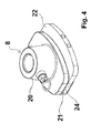
- FIGS. 3 to 7 show the press stamp in different views.
- the press stamp has a holder 20, on which a in FIG. 15 recognizable press-rod 39 can be fixed, which the movement of a in the Figures 14 and 15 recognizable press ram drive 38 transmits to the ram.
- the press ram 8 further has two ram elements 21 and 22, which are each equipped with finger-like projections 23.
- the first ram member 21 is fixedly connected to the holder 20.
- the second press-stamp element 22 is displaceable relative to the first press-stamp element.
- the second punch member 22 is this in an in FIG. 6 recognizable slot of the ram 8 out.
- the guide is also reinforced by the finger-like extensions 23, with which the two press-stamp elements 21 and 22 engage with each other.
- the finger-like extensions 23 of the two punch elements and the distances between the finger-like extensions 23 are formed identically in both punch elements 21, 22.
- the two pressing die elements 21 and 22 are covered by a plate 24.
- two pins 25 are slidably mounted. They are supported by springs, not visible in the drawing, on the second ram element 22. The springs push the two pins 25 to the outside. They ensure that without the action of an external force, the two press-stamp elements 21 and 22 in the starting position according to FIG. 4 have the greatest possible distance. Only by the action of an external force can they enter the in FIG.
- the chamber bottom 10 is shown, which is adjustable with respect to its chamber bottom surface just like the press ram.
- the structure of the chamber bottom with a holder 26, two chamber bottom elements 27 and 28, finger-like extensions 29, a plate 30 and pins 31 corresponds to the structure of the press ram.
- the functionality is identical.
- the force which presses the two chamber bottom elements 27 and 28 together is exerted on the chamber bottom 10 by the portioning chamber 9.
- the chamber bottom is additionally equipped with channels 32 and ports 33 to extract air from the portioning chamber or to introduce compressed air.
- the suction of air favors the complete filling of the portioning chamber with meat.
- the introduction of compressed air promotes the ejection of a portion from the portioning chamber.
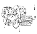
- FIG. 13 shows the portioning plate 2 with two ejection elements 13 and 16, a drive 34 for the knife, and the portioning plate drive 12 and additional molds 35 below the portioning plate 2, with which a portion can be divided into cubes.
- Each of the two molds 35 is equipped with a gate of several blades.
- the two ejection elements 13 and 16 press a portion disposed in a portioning chamber 9 down into the molds 35, whereby the portion is cut into cubes. The cubes then fall down and are sent for further processing.
- FIG. 14 shows the device in a similar view as in FIG. 1 , In contrast to FIG. 1 is the second conveyor 36 formed only half as long, the second conveyor 17 in FIG. 1 , In addition, the press unit 1 without pressing unit drive housing 6 is shown. Because of this, are in FIG. 14 the drive 37 for rotating the press unit 1 and the ram drive 38 can be seen. It is the punch drive 38 is a servo drive with an electric motor.
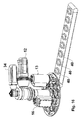
- FIG. 15 shows a section FIG. 14 , In the section, only the pressing unit 1 is shown.
- the pressing chamber housing 4b and the closing element 5b are missing, so that the pressing ram 8 with the pressing ram bar 39 can be seen.
- the press ram rod 39 transmits the stroke of the ram drive 38 to the ram 8.
- FIG. 16 shows a further embodiment of molds 40, in which a portion can be stored after cutting by the portioning and a discharge element 13.
- the molds 40 do not contain cutting tools.
Landscapes
- Life Sciences & Earth Sciences (AREA)
- Forests & Forestry (AREA)
- Engineering & Computer Science (AREA)
- Mechanical Engineering (AREA)
- Meat, Egg Or Seafood Products (AREA)
- Beans For Foods Or Fodder (AREA)
- Control And Other Processes For Unpacking Of Materials (AREA)
- Manufacturing And Processing Devices For Dough (AREA)
- Formation And Processing Of Food Products (AREA)
- General Preparation And Processing Of Foods (AREA)
- Processing Of Meat And Fish (AREA)
Abstract
Description
- Die Erfindung geht aus von einer Vorrichtung zum Portionieren von Lebensmitteln, insbesondere Fleisch.
- Derartige Vorrichtungen werden eingesetzt, um Lebensmittel in Portionen, beispielsweise in Form von Scheiben, gleichen Gewichts und/ oder gleicher Dicke aufzuschneiden. Zu den Lebensmitteln zählen beispielsweise frisches gewachsenes Fleisch, Wurst, Schinken, Käse, Gemüse oder Backwaren. Bekannte Vorrichtungen zum Aufschneiden von Wurst oder Käse werden auch als Slicer bezeichnet. Wurst oder Käse unterscheidet sich von frischem gewachsenem Fleisch aufgrund seiner Konsistenz dadurch, dass die entsprechenden Laibe eine feste Form mit einem durch die Herstellung vorgegebenen Volumen aufweisen. Die Slicer sind daher mit einer Vorrichtung zum Halten der Laibe während des Schneidens der Scheiben ausgestattet. Im Unterschied dazu weisen Stücke frischen gewachsenen Fleisches keine feste Form und kein vorgegebenes Volumen auf, sofern sie nicht tiefgekühlt oder gefroren sind. Zum Portionieren derartiger Fleischstücke genügt es daher nicht, die Fleischstücke wie bei bekannten Slicern zu halten. Vorrichtungen zum Portionieren weisen daher eine Presskammer auf, in der das Fleischstück zunächst zusammengepresst wird. Nach Abschluss des Pressvorgangs ist das Volumen, welches das Fleischstück ausfüllt, bekannt. Dies wird beim anschließenden Portionieren ausgenutzt.
- Portioniervorrichtungen für frisches gewachsenes Fleisch werden beispielsweise in Großküchen, bei der Herstellung von zusammengestellten und abgepackten Menüs und beim maschinellen Verpacken von aufgeschnittenen Lebensmitteln eingesetzt. Von einem Stück frischem, gewachsenem Fleisch oder einem anderen Lebensmittelstück werden einzelne Portionen, insbesondere Schnellbratstücke, wie Schnitzel, Steaks oder Medaillons abgetrennt. Dabei kommt es darauf an, dass die einzelnen Portionen ein vorgegebenes Gewicht und gegebenenfalls eine vorgegebene Dicke aufweisen. Die Scheiben müssen möglichst exakt portioniert sein, damit sie in ihrer Garzeit übereinstimmen, die einzelnen Portionen nicht zu unterschiedlich sind und das Gewicht auf einer vorgedruckten Packung angegeben werden kann.
- Aus dem Stand der Technik der
DE 103 04 773 A1 ist eine Vorrichtung zum Portionieren von Lebensmitteln mit einer Einlegetrommel mit mehreren Presskammern und mit einer Portioniertrommel mit mehreren Portionierkammern bekannt. Das Lebensmittelstück wird in einer Presskammer mit Hilfe eines seitlichen Deckels und eines Presstempels zusammengepresst und in eine Portionierkammer gedrückt. Anschließend wird die in der Portionierkammer befindliche Portion mit Hilfe eines zwischen der Presskammer und der Portionierkammer beweglichen Messers von dem Fleischstück abgetrennt und die Portion aus der Portionierkammer entfernt. Hierzu wird die Portioniertrommel gedreht. Dabei gelangt eine weitere Portionierkammer der Portioniertrommel in Verlängerung der Presskammer. Während die eine Portion aus einer der Portionierkammern entfernt wird, kann die andere Portionierkammer bereits wieder mit dem Lebensmittel befüllt werden. Dieser Vorgang wird so oft wiederholt, bis das gesamte Lebensmittel in Portionen aufgeteilt ist. Während des Portionierens kann in eine zweite Presskammer der Einlegetrommel ein weiteres Stück Lebensmittel eingelegt werden. Ist das erste Lebensmittelstück vollständig in Portionen aufgeteilt, so wird die Einlegetrommel gedreht. Die Portionierung kann anschließend mit dem zweiten Lebensmittelstück fortgesetzt werden. In die nun leere Presskammer kann erneut ein Lebensmittelstück eingelegt werden. - Als nachteilig erweist sich bei diesem bekannten Stand der Technik, dass der Querschnitt der Presskammern, des Pressstempels und der Portionierkammern fest vorgegeben ist und nicht an das jeweilige Lebensmittel angepasst werden kann. Dies ist jedoch bei Fleisch wichtig, da die zu portionierenden Stücke hinsichtlich ihrer Größe und ihrer Konsistenz stark voneinander abweichen können. Zur Anpassung kann der Benutzer allenfalls die Einlegetrommel und die Portioniertrommel austauschen, was mit einem hohen Aufwand an Zeit und Kosten verbunden ist. Verzichtet der Benutzer auf eine Anpassung, so führt dies zu unerwünschten Abweichungen beim Gewicht der einzelnen Portionen.
- Ferner erweist sich als nachteilig, dass die Scheiben bei der bekannten Vorrichtung nach dem Portionieren nicht automatisch weiterbearbeitet werden können, zum Beispiel in Würfel oder Streifen zerlegt oder mit einem für Cordonbleu-Schnitzel notwendigen Schnitt versehen werden.
- Die erfindungsgemäße Vorrichtung mit den Merkmalen des Anspruchs 1 zeichnet sich dadurch aus, dass ein Ausstoßelement an der Portionierplatte angeordnet ist, um eine abgetrennte Scheibe aus einer Portionierkammer auszustoßen. Das Ausstoßelement ist an derjenigen Seite der Portionierplatte angeordnet, die der Presskammer abgewandt ist. Außerdem ist das Ausstoßelement an der Position vorgesehen, an der die abgetrennten Scheiben auf einer Transporteinrichtung oder in einem Behälter abgelegt werden. Das Ausstoßelement unterstützt den Vorgang des Herauslösens einer abgetrennten Scheibe aus einer Portionierkammer. Darüber hinaus ist an der dem Ausstoßelement abgewandten Seite der Portionierplatte eine Form oder Mulde angeordnet, deren Querschnitt mit dem Querschnitt der Portionierkammern übereinstimmt. Durch das Ausstoßelement wird eine abgetrennte Scheiben aus einer Portionierkammer in die Form gedrückt. Während die Portionierplatte bewegt wird um eine weitere Portion von einem Stück abzuschneiden und eine andere abgetrennte Scheibe abzugeben, verbleibt die in der Form gehaltene Scheibe an ihrer Position und kann gegebenenfalls weiter bearbeitet werden. Dabei kann ausgenutzt werden, dass die Portion in der Form fixiert ist. Dies ist für die weitere Bearbeitung der Portion von Vorteil, da die Portion dem zur Bearbeitung eingesetzten Hilfsmittel oder Werkzeug in der Form nicht ausweichen kann. In der Form kann die Portion beispielsweise geschnitten und/ oder mit weiteren Zutaten versehen werden.
- An der Portionierplatte ist ein Ausstoßelement angeordnet, welches eine oder mehrere abgetrennte Portionen aus der Portionierkammer ausstößt. Es handelt sich hierbei beispielsweise um einen Stempel, der von einer Seite in die Portionierkammer einfährt und die Portionen aus der Portionierkammer verdrängt. Dadurch wird der Vorgang des Auswerfens einer oder mehrerer Portionen aus der Portionierkammer beschleunigt.
- An der dem Ausstoßelement abgewandten Seite der Portionierplatte ist eine Form angeordnet, deren Querschnitt mit dem Querschnitt der Portionierkammern übereinstimmt. Das Ausstoßelement sorgt dafür, dass die abgetrennte Portion in der durch die Portionierkammer vorgegebenen Form an eine zusätzliche Form übergeben wird. In dieser Form kann die weitere Be- oder Verarbeitung der Portion erfolgen. So kann die Form beispielsweise mit mehreren Klingen zum Schneiden von Würfeln oder Streifen ausgestattet sein. Die Portion wird damit während des Ausstoßens aus der Portionierkammer in weitere kleine Abschnitte aufgeteilt. Dies erfolgt in einem Arbeitsgang, ohne dass zusätzliche Stationen notwendig sind. Ferner kann während der weiteren Ver- und Bearbeitung der Portion der Portioniervorgang fortgesetzt werden.
- Nach einer vorteilhaften Ausgestaltung der Erfindung sind in oder an der Form Schneidwerkzeuge wie beispielsweise Messer, Schneiden oder Klingen angeordnet um die in der Form angeordnete Portion in Streifen oder Würfel zu schneiden oder eine eingeschnittene Tasche zu erzeugen. In derartige Taschen können Zutaten in die Portion gefüllt werden, beispielsweise bei einem Schnitzel Cordon bleu Käse und Schinken. Die Schneidwerkzeuge können entweder fest oder beweglich in oder an der Form angeordnet sein. Zum Schneiden ist eine Relativbewegung zwischen der zu schneidenden Portion und dem Schneidwerkzeug notwendig. Ist das Schneidwerkzeug ortfest in oder an der Form angeordnet, erfolgt das Schneiden beim Einführen der Portion in die Form und/ oder beim Herausnehmen der Portion aus der Form. Ist das Schneidwerkzeug beweglich an der Form angeordnet, kann das Schneiden auch während des Aufenthaltes der Portion in der Form erfolgen. Vorteilhafterweise ist die Form mit einer Führung für das bewegliche Schneidwerkzeug ausgestattet. Dabei kann es sich beispielsweise um einen Schlitz in der Form handeln.
- Nach einer vorteilhaften Ausgestaltung der Erfindung ist die Form in räumlicher Distanz zu der Presseinheit angeordnet. Sie behindert damit den Vorgang des Portionierens und Schneidens der einzelnen Portionen nicht. Das Ablegen der abgetrennten Portionen in der Form und gegebenenfalls die weitere Bearbeitung der Portion in der Form erfolgt erst, wenn der Schneidvorgang abgeschlossen ist. Zeitgleich zum Ablegen einer Portion in der Form kann an der Presseinheit eine weitere Portion von dem Stück abgeschnitten werden.
- Nach einer weiteren vorteilhaften Ausgestaltung der Erfindung ist der Kammerboden zur Einstellung der Tiefe der Portionierkammer verschiebbar angeordnet. Auf diese Weise können Portionen unterschiedlicher Dicke hergestellt werden. Darüber hinaus ist es möglich, mehrere Portionen in der Portionierkammer zu sammeln, bevor diese gemeinsam aus der Portionierkammer ausgeworfen werden. In diesem Fall verbleibt nach dem Abtrennen eine Portion in der Portionierkammer und der Kammerboden wird derart verschoben, dass eine weitere Portion in der Portionierkammer Platz findet. Diese Schritte können mehrfach wiederholt werden, bis die gesamte vorgegebene Tiefe der Portionierkammer ausgeschöpft ist und der Kammerboden in einer Endstellung angelangt ist.
- Nach einer weiteren vorteilhaften Ausgestaltung der Erfindung ist an der Portionierplatte auf der der Presseinheit abgewandten Seite ein Sammelbehälter zum Sammeln mehrerer Portionen angeordnet. Der Querschnitt des Sammelbehälters stimmt mit dem Querschnitt der Portionierkammern überein. Der Kammerboden der Portionierkammer ist in dem Sammelbehälter verschiebbar. Dies ermöglicht das Abschneiden mehrerer Portionen und Sammeln der Portionen, bevor diese aus der Portionierkammer ausgeworfen werden. In bevorzugter Weise ist der Sammelbehälter zusammen mit der Portionierplatte bewegbar, so dass beide Teile gemeinsam in eine Auswurfposition überführt werden können, während der Portioniervorgang mit einer anderen Portionierkammer der Portionierplatte fortgesetzt wird.
- Nach einer weiteren vorteilhaften Ausgestaltung der Erfindung ist der Kammerboden der Portionierkammer mit Kanälen zum Ansaugen und/ oder Ausstoßen von Luft oder sonstiger Gase ausgestattet. Die Vorrichtung weist Stifte auf, deren Querschnitt mit dem Querschnitt der Kanäle übereinstimmt oder geringfügig kleiner ist. Ferner ist ein Stiftantrieb vorgesehen, der die Stifte bei einer bestimmten Stellung der Portionierplatte in die Kanäle einfährt und die Kanäle dabei von Verunreinigungen befreit. Eine derartige Reinigung kann automatisch nach einer vorgegebenen Anzahl von Portionen oder bei Bedarf durchgeführt werden.
- Nach einer weiteren vorteilhaften Ausgestaltung der Erfindung ist die Presseinheit vertikal ausgerichtet. Dabei verlaufen die Presskammern in ihrer Längsrichtung in vertikaler Richtung. Der Pressstempel ist an der Unterseite der Presseinheit angeordnet. Das Schneidelement befindet sich an der Oberseite der Presseinheit. Die Portionierplatte ist oberhalb des Schneidelements angeordnet. Diese Anordnung zeichnet sich dadurch aus, dass die Presskammern bequem von oben mit einem Stück Lebensmittel befüllt werden können. Die von oben zugängliche Öffnung der Presskammer befindet sich in einer für den Benutzer angenehmen Höhe. Der Vorschub durch den Pressstempel erfolgt von unten nach oben. Die von dem Stück abgetrennten Portionen werden auf dem Messer liegend zusammen mit der Portionierkammer in eine Auswurfposition überführt. Bei der weiteren Rotationsbewegung des Schneidelements wird die Portionierkammer nach unten freigegeben. Durch ein von oben ansetzendes Ausstoßelement wird die abgetrennte Portion nach unten gedrückt und fällt auf eine Förder- oder Transporteinrichtung oder einen Behälter, in dem die abgetrennten Portionen gesammelt werden.
- Nach einer weiteren vorteilhaften Ausgestaltung der Erfindung sind unterhalb der Portionierplatte eine oder mehrere Transporteinrichtungen angeordnet, um die abgetrennten Portionen zu übernehmen und zu transportieren. Bei einer runden Portionierplatte mit beispielsweise vier Portionierkammern sind neben der Position des eigentlichen Portioniervorgang beispielsweise drei Positionen zum Ablegen einer abgetrennten Portion möglich. Jeder dieser Positionen kann eine separate Transporteinrichtung zugeordnet werden. Auf diese Weise können Portionen in Abhängigkeit von ihrem Gewicht oder ihrer Qualität auf unterschiedlichen Transporteinrichtungen abgelegt werden.
- Nach einer vorteilhaften Ausgestaltung der Erfindung ist die Portionierplatte um eine Achse drehbar angeordnet. Sie weist ferner eine geradzahlige Anzahl an Portionierkammern auf, die alle im gleichen radialen Abstand zur Achse und im gleichen Winkelabstand zueinander in der Portionierplatte angeordnet sind. Die drehbare Anordnung der Portionierplatte hat den Vorteil, dass die Portionierplatte schneller bewegt werden kann als bei einer verschiebbaren Anordnung. Dies führt zu kürzeren Taktzeiten. Haben alle Portionierkammern in der Portionierplatte denselben radialen Abstand zur Achse, und ist die Anzahl der Portionierkammern geradzahlig, so kann das Portionieren und Schneiden und das Ablegen von abgetrennten Portionen an unterschiedlichen Transporteinrichtungen gleichzeitig erfolgen. Dadurch wird die Taktzeit der Vorrichtung erhöht.
- Nach einer weiteren vorteilhaften Ausgestaltung der Erfindung sind die Presseinheit und die Portionierplatte um zwei parallele, räumlich getrennte Achsen drehbar. Die drehbare Anordnung sorgt dafür, dass die Bewegung der Presseinheit und der Portionierplatte schneller ablaufen kann als bei einer verschiebbaren Anordnung. Zwei räumlichen getrennte Achsen führen dazu, dass die Presseinheit und die Portionierplatte sich in ihren Bewegungen nicht gegenseitig behindern, und dass das Auswerfen oder Ablegen der abgetrennten Portionen aus den Portionierkammern der Portionierplatte in räumlicher Distanz zu der Presseinheit erfolgt und damit genügten Platz für den Transport der abgetrennten Portionen zur Verfügung steht. Parallele Achsen sind von Vorteil, da der Schnitt üblicherweise senkrecht zur Richtung des Vorschubs des Stücks in der Presskammer erfolgt und die Presskammern mit ihrer Längsachse parallel zu der Achse der Presseinheit angeordnet sind.
- Nach einer vorteilhaften Ausgestaltung der Erfindung sind der Pressstempel und/ oder der Kammerboden mit einem Kraftsensor ausgestattet. Über diesen Kraftsensor wird die Kraft gemessen, mit der das Stück gegen den Pressstempel drückt um umgekehrt. Entsprechendes gilt für den Kammerboden. Diese gemessene Kraft wird in die Regelung des Servoantriebs eingegeben.
- Nach einer weiteren vorteilhaften Ausgestaltung der Erfindung sind der Pressstempel und/ oder der Kammerboden mit einem Weg- oder Positionssensor ausgestattet. Während der Wegsensor einen von dem Pressstempel oder dem Kammerboden zurückgelegten Weg messen, bestimmt der Positionssensor die absolute Position des Pressstempels oder des Kammerbodens bezogen auf einen vorgegebenen Nullpunkt. Der durch den Sensor gemessene Wert wird in die Regelung des Servoantriebs eingegeben.
- Weitere Vorteile und vorteilhafte Ausgestaltungen der Erfindung sind der nachfolgenden Beschreibung, der Zeichnung und den Ansprüchen zu entnehmen.
- In der Zeichnung ist ein Ausführungsbeispiel einer erfindungsgemäßen Vorrichtung dargestellt. Es zeigen:
- Figur 1
- perspektivische Ansicht einer Vorrichtung zum Portionieren von Fleisch mit einer Presseinheit, einer Portionierplatte und mehreren Transporteinrichtungen,
- Figur 2
- weitere perspektivische Ansicht der Vorrichtung gemäß
Figur 1 , - Figur 3
- perspektivische Ansicht des Pressstempels mit kleinst möglicher Pressfläche einer Vorrichtung gemäß
Figur 1 , - Figur 4
- perspektivische Ansicht des Pressstempels gemäß
Figur 3 mit größtmöglicher Pressfläche, - Figur 5
- Pressstempel gemäß
Figur 3 mit vollständig herausgezogenem Pressstempelelement, - Figur 6
- Seitenansicht des Pressstempels gemäß
Figur 5 , - Figur 7
- Schnitt durch den Pressstempel gemäß
Figuren 3 bis 6 entlang der inFigur 6 mit A - A gekennzeichneten Ebene, - Figur 8
- perspektivische Ansicht eines Kammerbodens mit kleinstmöglicher Kammerbodenfläche,
- Figur 9
- Kammerboden gemäß
Figur 8 mit größtmöglicher Kammerbodenflä- che, - Figur 10
- Kammerboden gemäß
Figuren 8 und9 mit vollständig herausgezo- genem Kammerbodenelement, - Figur 11
- Seitenansicht des Kammerbodens gemäß
Figur 10 , - Figur 12
- Schnitt durch den Kammerboden gemäß
Figuren 8 bis 11 entlang der inFigur 11 mit A - A markierten Ebene, - Figur 13
- Portionierplatte einer Vorrichtung gemäß
Figuren 1 und2 mit zusätzlichen Formen zum Würfelschneiden, - Figur 14
- perspektivische Ansicht der Vorrichtung gemäß
Figur 1 ohne Presseinheit-Antrieb-Gehäuse, - Figur 15
- Ausschnitt aus
Figur 14 betreffend die Presseinheit, - Figur 16
- Portionierplatte einer Vorrichtung gemäß
Figuren 1 und2 mit zusätzlichen Formen zum weiteren Verarbeiten der Portionen. - In den
Figuren 1 und2 ist eine Vorrichtung zum Portionieren von Fleisch in zwei verschiedenen perspektivischen Ansichten dargestellt. Die Vorrichtung besteht im wesentlichen aus einer Presseinheit 1, einer Portionierplatte 2 und einem zwischen der Presseinheit und der Portionierplatte drehbar angeordneten Messer. Das Messer ist in der perspektivischen Darstellung gemäßFigur 1 und2 nicht erkennbar. Die Presseinheit 1 weist zwei Presskammern 3a und 3b auf, welche durch je ein Presskammergehäuse 4a und 4b und je ein Verschlusselement 5a und 5b begrenzt werden. In den Darstellungen gemäßFigur 1 und2 befindet sich die Presskammer 3a unterhalb der Portionierplatte 2 und ist deshalb nicht sichtbar. Dies gilt ebenso für das Verschlusselement 5a der Presskammer 3a. Lediglich das Presskammergehäuse 4a ist teilweise sichtbar. Die Presseinheit 1 wird durch einen Presseinheit-Antrieb zur Rotation angetrieben. Dieser ist in dem Presseinheit-Antrieb-Gehäuse 6 angeordnet. Die Presseinheit 1 nimmt im wesentlichen zwei Positionen ein. In einer ersten in denFiguren 1 und2 dargestellten Einstellung befindet sich die erste Presskammer 3a unterhalb der Portionierplatte 2 und die zweite Presskammer 3b in maximaler Entfernung von der Portionierplatte 2. In dieser Einstellung wird das in dieser Presskammer 3a befindliche Fleischstück in Portionen aufgeteilt. Die zweite Presskammer 3b ist nicht durch die Portionierplatte 2 abgedeckt und daher von oben frei zugänglich. In sie kann ein Stück Fleisch von oben eingeführt werden. Um das Einführen zu erleichtern, ist das Verschlusselement 5b derart weit aus dem Presskammergehäuse 4b herausgezogen, dass der Querschnitt der Presskammer 3b seine größtmögliche Ausgangseinstellung aufweist. Sobald ein in der Zeichnung nicht dargestelltes Fleischstück in die Presskammer 3b eingelegt ist, wird das Verschlusselement 5b mit Hilfe eines Verschlusselement-Antriebs 7 in das Presskammergehäuse 4b hineingeschoben, um den Querschnitt der Presskammer 3b zu verkleinern. Ein in der Zeichnung nicht dargestellter Kraftsensor bestimmt dabei die Kraft, mit der das Fleischstück dem Verschlusselement-Antrieb 7 entgegen wirkt. Bei Erreichen einer vorgegebenen maximalen Kraft wird das Verschlusselement 5b in seiner Position arretiert. Der zu der betreffenden Einstellung des Verschlusselements 5b gehörende Querschnitt der Presskammer wird anhand eines, ebenfalls in der Zeichnung nicht erkennbaren Wegsensors festgestellt. - Sobald das in der ersten Presskammer 3a angeordnete Fleischstück vollständig in Portionen aufgeteilt wurde, wird die Presseinheit 1 gedreht und die mit einem Fleischstück befüllte zweite Portionierkammer 3b unter die Portionierplatte 2 bewegt. Die erste Presskammer 3a ist nun leer und kann erneut mit einem Fleischstück befüllt werden. Dies erfolgt auf dieselbe Weise wie zuvor beschrieben. Das Verschieben der Verschlusselemente 5a und 5b kann vor, während oder nach der Rotation der Presseinheit 1 erfolgen.
- Die beiden Presskammern 3a und 3b sind identisch aufgebaut.
- Zum Portionieren wird in die unterhalb der Portionierplatte 2 angeordnete Presskammer 3a oder 3b von unten ein Pressstempel 8 eingeführt. Der Pressstempel kann auch als Presskolben bezeichnet werden. Er ist in den
Figuren 1 und2 nicht erkennbar. Er ist in denFiguren 3 bis 7 und15 dargestellt. Der Pressstempel 8 drückt das Fleisch von unten nach oben in eine oberhalb der Presskammer 3a oder 3b angeordnete Portionierkammer 9 der Portionierplatte 2. Die Portionierplatte 2 ist mit insgesamt 4 Portionierkammern 9 ausgestattet. Oberhalb der Position, an der eine Presskammer 3a oder 3b mit einer Portionierkammer 9 zur Deckung gebracht werden können, ist ein Kammerboden 10 in vertikaler Richtung verschiebbar angeordnet. Zum Verschieben des Kammerbodens 10 ist ein Kammerboden-Antrieb 11 vorgesehen. Es handelt sich hierbei um einen Servoantrieb mit einem Elektromotor. Der Kammerboden 10 wird von oben in eine Portionierkammer 9 eingeführt. Die Dicke und damit das Gewicht einer Portion hängt davon ab, wie weit beziehungsweise wie tief der Kammerboden in die Portionierkammer hineinragt. Das Gewicht der Portionen sowie deren Dicke ist damit über die Position des Kammerbodens 10 einstellbar. - Das Fleischstück wird von unten durch den Pressstempel 8 in die durch den Kammerboden 10 verschlossene Portionierkammer 9 gepresst, so dass das Fleisch die gesamte Portionierkammer ausfüllt. Dabei drücken der Pressstempel 8 und der Kammerboden 10 gegeneinander. Die Portion, welche sich in der Portionierkammer 9 befindet, wird durch ein nicht dargestelltes Messer vom Fleischstück abgeschnitten. Zur Entlastung des Messers während des Schneidvorgangs können der Pressstempel 8 und/ oder der Kammerboden 10 zurückgezogen werden. Anschließend wird der Kammerboden 10 durch den Kammerboden-Antrieb 11 nach oben gezogen, so dass die Portionierplatte 2 durch den Portionierplatten-Antrieb 12 gedreht werden kann. Die Drehung erfolgt in diesem Fall um 90°, 180° oder 270°. Dies hängt von der Qualität der Portion ab. Endstücke des Fleischstücks, die ein geringeres Gewicht aufweisen als das vorgegebene Sollgewicht, können beispielsweise von den übrigen Portionen getrennt werden. Das in der Zeichnung nicht erkennbare Messer wird zusammen mit der Portionierplatte 2 gedreht, bis sich die abgetrennte Portion oberhalb der vorgesehenen Auswurfposition befindet. Anschließend wird das Messer in seine Ausgangsposition oberhalb der Presskammer zurückgeführt, um die nächste Portion abzuschneiden. Die Portionierkammer 9 ist nun nach unten offen. Mit Hilfe eines stempelartigen Ausstoßelements 13 wird die abgetrennte Portion nach unten aus der Portionierkammer 9 herausgedrückt und fällt in einen Behälter 14, der durch eine Transporteinrichtung 15 bewegt wird. Ein zweites stempelartiges Austoßstelement 16 befindet sich oberhalb einer zweiten Transporteinrichtung 17. Beide Auswurfelemente 13 und 16 sind mit Antrieben 18 und 19 ausgestattet.
- Während eine Portion mit Hilfe eines der beiden Auswurfelemente 13 oder 16 aus einer Portionierkammer 9 ausgestoßen und in einen Behälter 14 abgelegt wird, wird in einer weiteren Portionierkammer 9 der Portionierplatte 2, welche sich oberhalb der Presskammer 3a befindet, eine Portion abgemessen und durch das Messer von dem Fleischstück abgeschnitten. Dieser Vorgang wird so oft wiederholt, bis das gesamte in der Presskammer 3a angeordnete Fleischstück in Portionen aufgeteilt ist. Anschließend wird die Presseinheit 1 gedreht, um ein weiteres Fleischstück auf dieselbe Weise in Portionen aufzuteilen.
- Beim Übergang von der Position einer Presskammer 3a oder 3b unterhalb der Portionierplatte 2 in eine Position zum Befüllen der Presskammer wird das zugehörige Verschlusselement 5a oder 5b aus dem Presskammergehäuse 4a oder 4b herausgezogen, so dass sich der Querschnitt der Presskammer wieder vergrößert und das Einlegen eines Fleischstücks erleichtert wird. Die Position und die Kraft des Verschlusselements 5a oder 5b werden nicht nur beim Einlegen eines neuen Fleischstücks, sondern auch während des Portioniervorganges kontinuierlich erfasst. Fällt die Kraft aufgrund der Form des Fleischstücks während des Portioniervorgangs ab oder steigt sie an, so kann die Position des Verschlusselements während des Portioniervorgangs angepasst werden.
- Die
Figuren 3 bis 7 zeigen den Pressstempel in verschiedenen Ansichten. Der Pressstempel weist eine Halterung 20 auf, an dem eine inFigur 15 erkennbare Pressstempelstange 39 befestigt werden kann, welche die Bewegung eines in denFiguren 14 und15 erkennbaren Pressstempel-Antriebs 38 auf den Pressstempel überträgt. Der Pressstempel 8 weist ferner zwei Pressstempelelemente 21 und 22 auf, die jeweils mit fingerartigen Fortsätzen 23 ausgestattet sind. Das erste Pressstempelelement 21 ist fest mit der Halterung 20 verbunden. Das zweite Pressstempelelement 22 ist gegenüber dem ersten Pressstempelelement verschiebbar. Das zweite Pressstempelelement 22 ist hierzu in einem inFigur 6 erkennbaren Schlitz des Pressstempels 8 geführt. Die Führung wird außerdem durch die fingerartigen Fortsätze 23 verstärkt, mit denen die beiden Pressstempelelemente 21 und 22 ineinander greifen. Die fingerartigen Fortsätze 23 der beiden Pressstempelelemente sowie die Abstände zwischen den fingerartigen Fortsätzen 23 sind bei beiden Pressstempelelementen 21, 22 identisch ausgebildet. An der der Presskammer zugewandten Seite sind die beiden Pressstempelelemente 21 und 22 durch eine Platte 24 abgedeckt. In zwei der fingerartigen Fortsätze 23 des zweiten Pressstempelelements 22 sind zwei Stifte 25 verschiebbar gelagert. Sie stützen sich durch in der Zeichnung nicht erkennbare Federn an dem zweiten Pressstempelelement 22 ab. Die Federn drücken die beiden Stifte 25 nach außen. Sie sorgen dafür, dass ohne Einwirkung einer äußeren Kraft die beiden Pressstempelelemente 21 und 22 in der Ausgangsstellung gemäßFigur 4 den größtmöglichen Abstand aufweisen. Nur durch Einwirkung einer äußeren Kraft können sie in die inFigur 3 dargestellte Position gebracht werden, in der die fingerartigen Fortsätze 23 derart nah beieinander liegen, dass kein Zwischenraum und keine Lücke zwischen ihnen besteht. In dieser Einstellung sind die Stifte 25 vollständig in die hierfür vorgesehenen Kanäle der fingerartigen Fortsätze 23 eingedrückt. Die Kraft, welche die beiden Pressstempelelemente 21 und 22 zusammen drückt, wird durch ein Presskammergehäuse 4a, 4b und das zugehörige Verschlusselement 5a, 5b ausgeübt. - In den
Figuren 8 bis 12 ist der Kammerboden 10 dargestellt, der hinsichtlich seiner Kammerbodenfläche genau wie der Pressstempel einstellbar ist. Der Aufbau des Kammerbodens mit einer Halterung 26, zwei Kammerbodenelementen 27 und 28, fingerartigen Fortsätzen 29, einer Platte 30 sowie Stiften 31 entspricht dem Aufbau des Pressstempels. Die Funktionsweise ist identisch. Die Kraft, welche die beiden Kammerbodenelemente 27 und 28 zusammen drückt, wird bei dem Kammerboden 10 durch die Portionierkammer 9 ausgeübt. Darüber hinaus ist der Kammerboden zusätzlich mit Kanälen 32 und Anschlüssen 33 ausgestattet, um aus der Portionierkammer Luft abzusaugen oder Druckluft einzuleiten. Das Ansaugen von Luft begünstigt das vollständige Ausfüllen der Portionierkammer mit Fleisch. Das Einleiten von Druckluft begünstigt den Auswurf einer Portion aus der Portionierkammer. -
Figur 13 zeigt die Portionierplatte 2 mit zwei Ausstoßelementen 13 und 16, einem Antrieb 34 für das Messer, sowie dem Portionierplatten-Antrieb 12 und zusätzlichen Formen 35 unterhalb der Portionierplatte 2, mit denen eine Portion in Würfel aufgeteilt werden kann. Jede der beiden Formen 35 ist mit einem Gatter aus mehreren Klingen ausgestattet. Die beiden Ausstoßelemente 13 und 16 drücken eine in einer Portionierkammer 9 angeordnete Portion nach unten in die Formen 35, wodurch die Portion in Würfel aufgeschnitten wird. Die Würfel fallen anschließend nach unten und werden der weiteren Verarbeitung zugeführt. -
Figur 14 zeigt die Vorrichtung in einer ähnlichen Ansicht wie inFigur 1 . Im Unterschied zuFigur 1 ist die zweite Transporteinrichtung 36 nur halb so lang ausgebildet wird die zweite Transporteinrichtung 17 inFigur 1 . Außerdem ist die Presseinheit 1 ohne Presseinheit-Antrieb-Gehäuse 6 dargestellt. Aus diesem Grund sind inFigur 14 der Antrieb 37 zum Rotieren der Presseinheit 1 und der Pressstempel-Antrieb 38 erkennbar. Es handelt sich bei dem Pressstempel-Antrieb 38 um einen Servoantrieb mit einem Elektromotor. -
Figur 15 zeigt einen Ausschnitt ausFigur 14 . In dem Ausschnitt ist lediglich die Presseinheit 1 dargestellt. Das Presskammergehäuse 4b und das Verschlusselement 5b fehlen, so dass der Pressstempel 8 mit der Pressstempelstange 39 erkennbar sind. Die Pressstempelstange 39 überträgt den Hub des Pressstempel-Antriebs 38 auf den Pressstempel 8. -
Figur 16 zeigt ein weiteres Ausführungsbeispiel an Formen 40, in die eine Portion nach dem Schneiden durch die Portionierplatte und ein Ausstoßelement 13 abgelegt werden kann. Die Formen 40 enthalten keine Schneidwerkzeuge. - Sie führen lediglich die Portionen der weiteren Verarbeitung zu und erhalten dabei die durch die Portionierkammern vorgegebene Form.
- Sämtliche Merkmale der Erfindung können sowohl einzeln als auch in beliebiger Kombination miteinander erfindungswesentlich sein.
-
- 1
- Presseinheit
- 2
- Portionierplatte
- 3a
- Presskammer
- 3b
- Presskammer
- 4a
- Presskammergehäuse
- 4b
- Presskammergehäuse
- 5a
- Verschlusselement
- 5b
- Verschlusselement
- 6
- Presseinheit-Antrieb-Gehäuse
- 7
- Verschlusselement-Antrieb
- 8
- Pressstempel
- 9
- Portionierkammer
- 10
- Kammerboden
- 11
- Kammerboden-Antrieb
- 12
- Portionierplatten-Antrieb
- 13
- Ausstoßelement
- 14
- Behälter
- 15
- Transporteinrichtung
- 16
- zweites Ausstoßelement
- 17
- zweite Transporteinrichtung
- 18
- Antrieb des ersten Ausstoßelements
- 19
- Antrieb des zweiten Ausstoßelements
- 20
- Halterung am Pressstempel
- 21
- Pressstempelelement
- 22
- Pressstempelelement
- 23
- fingerartiger Fortsatz
- 24
- Platte
- 25
- Stift
- 26
- Halterung am Kammerboden
- 27
- Kammerbodenelement
- 28
- Kammerbodenelement
- 29
- fingerartiger Fortsatz
- 30
- Platte
- 31
- Stift
- 32
- Kanal für Druckluft
- 33
- Anschluss für Druckluft
- 34
- Messerantrieb
- 35
- Form zum Würfelschneiden
- 36
- zweite Transporteinheit
- 37
- Antrieb zum Rotieren der Presseinheit
- 38
- Pressstempel-Antrieb
- 39
- Pressstempelstange
- 40
- Form
Claims (4)
- Vorrichtung zum Portionieren von Lebensmitteln, insbesondere von Fleisch, in Portionen mit vorgegebenem Gewicht und/ oder vorgegebener Dicke
mit einer Presseinheit (1) mit mindestens zwei länglichen Presskammern (3a, 3b),
mit mindestens einem Pressstempel (8) für die Presskammern (3a, 3b), welcher mit einem Pressstempel-Antrieb (38) ausgestattet ist um den Pressstempel (8) in Längsrichtung der Presskammer (3a, 3b) zu verschieben,
mit einer Portionierplatte (2) mit mehreren Portionierkammern (9), mit einem Portionierplatten-Antrieb (12) um die Portionierplatte (2) relativ zur Presseinheit (1) zu bewegen,
mit einem Schneidelement zwischen der Presseinheit (1) und der Portionierplatte (2),
mit einem Schneidelement-Antrieb (34) um das Schneidelement relativ zu der Presseinheit (1) zu bewegen,
mit einem Ausstoßelement (13, 16) an der Portionierplatte (2), welches eine oder mehrere abgetrennte Portionen aus der Portionierkammer (9) ausstößt,
mit einer an der dem Ausstoßelement (13, 16) abgewandten Seite der Portionierplatte (2) angeordneten Form (35, 40), deren Querschnitt mit dem Querschnitt der Portionierkammern (9) übereinstimmt zur weiteren Be- und Verarbeitung der Portion. - Vorrichtung nach Anspruch 1, dadurch gekennzeichnet, dass in oder an der Form (35) mindestens ein Schneidwerkzeug angeordnet ist.
- Vorrichtung nach Anspruch 9, dadurch gekennzeichnet, dass die Form (35) eine Führung für das Schneidwerkzeug aufweist.
- Vorrichtung nach einem der Ansprüche 8 bis 10, dadurch gekennzeichnet, dass die Form (35, 40) in räumlicher Distanz zu der Presseinheit (1) angeordnet ist.
Applications Claiming Priority (2)
| Application Number | Priority Date | Filing Date | Title |
|---|---|---|---|
| DE102007021509 | 2007-05-04 | ||
| EP20080758005 EP2144735B1 (de) | 2007-05-04 | 2008-05-05 | Vorrichtung zum portionieren von lebensmitteln |
Related Parent Applications (1)
| Application Number | Title | Priority Date | Filing Date |
|---|---|---|---|
| EP08758005.6 Division | 2008-05-05 |
Publications (2)
| Publication Number | Publication Date |
|---|---|
| EP2241421A1 true EP2241421A1 (de) | 2010-10-20 |
| EP2241421B1 EP2241421B1 (de) | 2012-07-11 |
Family
ID=39766831
Family Applications (3)
| Application Number | Title | Priority Date | Filing Date |
|---|---|---|---|
| EP20100006820 Not-in-force EP2248641B1 (de) | 2007-05-04 | 2008-05-05 | Vorrichtung und Verfahren zum Portionieren von Lebensmitteln |
| EP20080758005 Active EP2144735B1 (de) | 2007-05-04 | 2008-05-05 | Vorrichtung zum portionieren von lebensmitteln |
| EP20100006821 Not-in-force EP2241421B1 (de) | 2007-05-04 | 2008-05-05 | Vorrichtung zum Portionieren von Lebensmitteln |
Family Applications Before (2)
| Application Number | Title | Priority Date | Filing Date |
|---|---|---|---|
| EP20100006820 Not-in-force EP2248641B1 (de) | 2007-05-04 | 2008-05-05 | Vorrichtung und Verfahren zum Portionieren von Lebensmitteln |
| EP20080758005 Active EP2144735B1 (de) | 2007-05-04 | 2008-05-05 | Vorrichtung zum portionieren von lebensmitteln |
Country Status (8)
| Country | Link |
|---|---|
| US (1) | US8622727B2 (de) |
| EP (3) | EP2248641B1 (de) |
| AT (2) | ATE500935T1 (de) |
| DE (2) | DE102008022173A1 (de) |
| DK (1) | DK2144735T3 (de) |
| ES (2) | ES2381438T3 (de) |
| PL (2) | PL2248641T3 (de) |
| WO (1) | WO2008135025A2 (de) |
Cited By (1)
| Publication number | Priority date | Publication date | Assignee | Title |
|---|---|---|---|---|
| EP3542979A1 (de) * | 2018-03-19 | 2019-09-25 | TVI Entwicklung und Produktion GmbH | Verfahren zum verpressen und insbesondere anschliessend aufschneiden von elastischen laiben, insbesondere fleisch-laiben sowie schneidemaschine hierfür |
Families Citing this family (5)
| Publication number | Priority date | Publication date | Assignee | Title |
|---|---|---|---|---|
| DE102009054081B4 (de) * | 2009-11-20 | 2012-03-22 | Thomas Völkl | Würfelschneider |
| US20130337135A1 (en) * | 2012-06-13 | 2013-12-19 | Michael F. Vieira | Apparatuses for producing food products from fish and chicken shims and associated systems and methods |
| US10849329B2 (en) * | 2016-02-08 | 2020-12-01 | Angela Marie Hotz | Hamburger press patty express |
| DE102018132899B3 (de) * | 2018-12-19 | 2020-03-26 | Martin Bergmann | Magazinrevolvereinrichtung für Portioniermaschine |
| DE102024107415B4 (de) * | 2024-03-15 | 2026-02-05 | Tvi Entwicklung Und Produktion Gmbh | Aufschneidemaschine |
Citations (3)
| Publication number | Priority date | Publication date | Assignee | Title |
|---|---|---|---|---|
| US6383068B1 (en) * | 1998-04-09 | 2002-05-07 | Tyson Foods, Inc. | Food portioning apparatus and method |
| DE10304773A1 (de) | 2003-02-05 | 2004-08-19 | Maja-Maschinenfabrik Hermann Schill Gmbh & Co. Kg | Vorrichtung und Verfahren zum Portionieren eines Lebensmittelstücks |
| DE102004041915A1 (de) * | 2004-08-30 | 2006-03-16 | Völkl, Thomas | Vorrichtung und Verfahren zum Portionieren |
Family Cites Families (48)
| Publication number | Priority date | Publication date | Assignee | Title |
|---|---|---|---|---|
| US3687067A (en) * | 1969-11-20 | 1972-08-29 | Bettcher Industries | Food press |
| US3648600A (en) * | 1970-03-02 | 1972-03-14 | Jaccard Corp | Meat-pressing apparatus |
| US3943601A (en) * | 1970-04-27 | 1976-03-16 | Kuhlman Harvey G | Moldable food depositing apparatus |
| US3683797A (en) * | 1970-08-27 | 1972-08-15 | Bettcher Industries | Food press |
| US3724026A (en) * | 1970-10-30 | 1973-04-03 | Armour & Co | Producing molded meat sticks |
| US3704665A (en) * | 1971-04-21 | 1972-12-05 | Bettcher Industries | Food press and dies |
| US3753398A (en) * | 1971-08-20 | 1973-08-21 | Cashin System | Meat press |
| US3756231A (en) * | 1971-10-18 | 1973-09-04 | H Ross | Meat-forming press |
| US3887964A (en) * | 1972-01-24 | 1975-06-10 | Formax Inc | Food patty molding machine |
| USRE30096E (en) * | 1972-01-24 | 1979-09-18 | Formax, Inc. | Food patty molding machine |
| CA965753A (en) * | 1972-09-01 | 1975-04-08 | A.B.R. Food Machinery (Canada) Limited | Meat packaging and pressing apparatus |
| US3992734A (en) * | 1973-05-03 | 1976-11-23 | Agence Nationale De Valorisation De La Recherche (Anvar) | Boning meat |
| US4043728A (en) * | 1975-10-06 | 1977-08-23 | Hollymatic Corporation | Molding apparatus |
| US4037827A (en) * | 1975-12-15 | 1977-07-26 | F.P.E.C. Corporation | Food product mixer with an improved door mechanism |
| US4057874A (en) * | 1976-03-26 | 1977-11-15 | Walker Jr Fred T | Food pattie molding tool |
| US4113415A (en) * | 1976-11-01 | 1978-09-12 | Hollymatic Corporation | Molding apparatus |
| US4229859A (en) * | 1978-05-01 | 1980-10-28 | Gagliardi Bros., Inc. | Meat patty processing method and apparatus |
| US4276318A (en) * | 1978-11-09 | 1981-06-30 | Armour And Company | Apparatus and method for molding meat patties |
| US4193167A (en) * | 1978-11-09 | 1980-03-18 | Armour And Company | Apparatus for molding meat patties |
| US4302868A (en) * | 1979-10-22 | 1981-12-01 | Hollymatic Corporation | Molding apparatus |
| US4483046A (en) * | 1980-08-21 | 1984-11-20 | Briddell Charles D | Crab meat processing machine |
| US4516291A (en) * | 1983-05-31 | 1985-05-14 | Goldberger Foods Inc. | Apparatus and process for forming meat patties |
| US4646385A (en) * | 1985-02-04 | 1987-03-03 | C. D. Briddell Inc. | Methods and apparatus for forming loose meat into lumps |
| JPS61282063A (ja) * | 1985-06-10 | 1986-12-12 | Kibun Kk | 食品押出成形装置 |
| WO1987002549A1 (fr) * | 1985-10-31 | 1987-05-07 | Baechtold Walter | Dispositif pour la fabrication de produits formes a base de viande |
| US4807524A (en) * | 1986-03-25 | 1989-02-28 | Kabushiki Kaisha Ikeuchi Tekkosho | Method and apparatus for producing a food product |
| US4735031A (en) * | 1986-09-12 | 1988-04-05 | Langen Research B.V. | Apparatus for packing and processing a meat product |
| ES2036204T3 (es) * | 1986-09-22 | 1993-05-16 | Langen Research B.V. | Metodo y dispositivo para deshuesar porciones de carne. |
| DE3705118C2 (de) | 1987-02-18 | 1995-12-21 | Toni Reifenhaeuser | Verfahren und Vorrichtung zum Schneiden eines Fleischstückes |
| DE3729061A1 (de) * | 1987-08-31 | 1989-03-09 | Glass Horst | Verfahren und vorrichtung zum schneiden von lebensmittelstraengen |
| US5021025A (en) * | 1989-09-12 | 1991-06-04 | Wagner Richard C | Method and machine for making food patties |
| US5030164A (en) * | 1989-09-12 | 1991-07-09 | Hollymatic Corporation | Method and machine for making food patties |
| EP0539603A4 (en) * | 1991-05-13 | 1994-07-06 | Hitec Co Ltd | Device for making ham or the like |
| US5445512A (en) * | 1994-01-27 | 1995-08-29 | Marlen Research Corporation | Segmented piston face plate assembly for patty forming apparatus |
| US5569070A (en) * | 1995-06-07 | 1996-10-29 | Smith; Jeffrey P. | Controlled volume meat apportioner |
| US5655436A (en) * | 1996-08-29 | 1997-08-12 | Progressive Technology Of Manitowoc, Inc. | Food patty molding machine |
| US5730650A (en) * | 1996-08-29 | 1998-03-24 | Progressive Technology Of Wisconsin, Inc. | Food patty molding machine |
| FR2754207B1 (fr) * | 1996-10-07 | 1998-11-06 | Emsens Michel | Machine pour le decoupage en morceaux calibres de produits alimentaires |
| DE19806561C2 (de) * | 1998-02-17 | 2000-04-27 | Thomas Voelkl | Kalibrierschneidvorrichtung |
| JP3365758B2 (ja) * | 2000-05-09 | 2003-01-14 | 株式会社タカミ | 食肉切断機及び食肉切断方法 |
| ITRE20020010A1 (it) * | 2002-02-01 | 2003-08-01 | Giorgio Grasselli | Metodo e dispositivo per tagliare pezzi di carne in fette di ugual peso. |
| US6688961B2 (en) * | 2002-02-07 | 2004-02-10 | Jeffrey P. Smith | Poultry breast meat apportioning method |
| US6921326B2 (en) * | 2002-02-07 | 2005-07-26 | Jeffrey P. Smith | Poultry breast meat apportioning method |
| US20090255419A1 (en) * | 2002-11-08 | 2009-10-15 | Kirsch Sam A | Method and apparatus for making a flaky meat product |
| US7204748B2 (en) * | 2004-10-29 | 2007-04-17 | Remington Holdings Llc | Poultry breast portion sizing apparatus |
| US8616099B2 (en) | 2005-05-19 | 2013-12-31 | Marel Hf | Portioning of food stuff |
| CA2676361A1 (en) * | 2007-01-23 | 2008-07-31 | Formax, Inc. | Food patty molding machine |
| US8029265B2 (en) * | 2008-03-28 | 2011-10-04 | Progressive International Corporation | Burger press |
-
2008
- 2008-05-05 PL PL10006820T patent/PL2248641T3/pl unknown
- 2008-05-05 EP EP20100006820 patent/EP2248641B1/de not_active Not-in-force
- 2008-05-05 AT AT08758005T patent/ATE500935T1/de active
- 2008-05-05 EP EP20080758005 patent/EP2144735B1/de active Active
- 2008-05-05 DE DE102008022173A patent/DE102008022173A1/de not_active Withdrawn
- 2008-05-05 DK DK08758005T patent/DK2144735T3/da active
- 2008-05-05 DE DE200850002815 patent/DE502008002815D1/de active Active
- 2008-05-05 US US12/598,863 patent/US8622727B2/en not_active Expired - Fee Related
- 2008-05-05 AT AT10006820T patent/ATE546264T1/de active
- 2008-05-05 WO PCT/DE2008/000744 patent/WO2008135025A2/de not_active Ceased
- 2008-05-05 ES ES10006820T patent/ES2381438T3/es active Active
- 2008-05-05 EP EP20100006821 patent/EP2241421B1/de not_active Not-in-force
- 2008-05-05 PL PL08758005T patent/PL2144735T3/pl unknown
- 2008-05-05 ES ES08758005T patent/ES2361086T3/es active Active
Patent Citations (3)
| Publication number | Priority date | Publication date | Assignee | Title |
|---|---|---|---|---|
| US6383068B1 (en) * | 1998-04-09 | 2002-05-07 | Tyson Foods, Inc. | Food portioning apparatus and method |
| DE10304773A1 (de) | 2003-02-05 | 2004-08-19 | Maja-Maschinenfabrik Hermann Schill Gmbh & Co. Kg | Vorrichtung und Verfahren zum Portionieren eines Lebensmittelstücks |
| DE102004041915A1 (de) * | 2004-08-30 | 2006-03-16 | Völkl, Thomas | Vorrichtung und Verfahren zum Portionieren |
Cited By (2)
| Publication number | Priority date | Publication date | Assignee | Title |
|---|---|---|---|---|
| EP3542979A1 (de) * | 2018-03-19 | 2019-09-25 | TVI Entwicklung und Produktion GmbH | Verfahren zum verpressen und insbesondere anschliessend aufschneiden von elastischen laiben, insbesondere fleisch-laiben sowie schneidemaschine hierfür |
| US11213037B2 (en) | 2018-03-19 | 2022-01-04 | TVI Entwicklung & Produktion GmbH | Process for cutting elastic strands, in particular meat strands and cutting machine therefor |
Also Published As
| Publication number | Publication date |
|---|---|
| DK2144735T3 (da) | 2011-06-20 |
| EP2248641A1 (de) | 2010-11-10 |
| DE502008002815D1 (de) | 2011-04-21 |
| WO2008135025A3 (de) | 2010-05-14 |
| EP2241421B1 (de) | 2012-07-11 |
| EP2144735A2 (de) | 2010-01-20 |
| PL2248641T3 (pl) | 2012-07-31 |
| EP2248641B1 (de) | 2012-02-22 |
| ES2361086T3 (es) | 2011-06-13 |
| EP2144735B1 (de) | 2011-03-09 |
| US8622727B2 (en) | 2014-01-07 |
| ATE500935T1 (de) | 2011-03-15 |
| DE102008022173A1 (de) | 2008-11-06 |
| ES2381438T3 (es) | 2012-05-28 |
| WO2008135025A2 (de) | 2008-11-13 |
| PL2144735T3 (pl) | 2011-07-29 |
| ATE546264T1 (de) | 2012-03-15 |
| US20110159162A1 (en) | 2011-06-30 |
Similar Documents
| Publication | Publication Date | Title |
|---|---|---|
| EP2532493B1 (de) | Portioniermaschine | |
| EP3448641B1 (de) | Schneidemaschine sowie verfahren zum aufschneiden von elastischen strängen, insbesondere fleischsträngen | |
| EP2324973B1 (de) | Würfelschneider | |
| EP2241421B1 (de) | Vorrichtung zum Portionieren von Lebensmitteln | |
| EP1445078B1 (de) | Vorrichtung und Verfahren zum Portionieren eines Lebensmittelstücks | |
| EP2227964B1 (de) | Vorrichtung und Verfahren zum Portionieren | |
| EP1819489B1 (de) | Vorrichtung und verfahren zum portionieren | |
| EP1003631B1 (de) | Vorrichtung zum portionieren eines fleischstücks | |
| EP0237715B1 (de) | Vorrichtung zum Schneiden von Lebensmitteln | |
| EP2107962B1 (de) | Vorrichtung und verfahren zum portionieren | |
| EP0306012A2 (de) | Verfahren und Vorrichtung zum Schneiden von Lebensmittelsträngen | |
| DE19921047A1 (de) | Vorrichtung zum Portionieren eines Fleischstücks | |
| DE29723638U1 (de) | Vorrichtung zum Portionieren eines Fleischstücks | |
| DE29923724U1 (de) | Vorrichtung zum portionieren eines fleischstückes |
Legal Events
| Date | Code | Title | Description |
|---|---|---|---|
| PUAI | Public reference made under article 153(3) epc to a published international application that has entered the european phase |
Free format text: ORIGINAL CODE: 0009012 |
|
| AC | Divisional application: reference to earlier application |
Ref document number: 2144735 Country of ref document: EP Kind code of ref document: P |
|
| AK | Designated contracting states |
Kind code of ref document: A1 Designated state(s): AT BE BG CH CY CZ DE DK EE ES FI FR GB GR HR HU IE IS IT LI LT LU LV MC MT NL NO PL PT RO SE SI SK TR |
|
| 17P | Request for examination filed |
Effective date: 20110118 |
|
| 17Q | First examination report despatched |
Effective date: 20110908 |
|
| REG | Reference to a national code |
Ref country code: DE Ref legal event code: R079 Ref document number: 502008007714 Country of ref document: DE Free format text: PREVIOUS MAIN CLASS: B26D0007060000 Ipc: B26D0007020000 |
|
| GRAP | Despatch of communication of intention to grant a patent |
Free format text: ORIGINAL CODE: EPIDOSNIGR1 |
|
| RIC1 | Information provided on ipc code assigned before grant |
Ipc: B26D 7/02 20060101AFI20111213BHEP Ipc: B26D 7/06 20060101ALI20111213BHEP |
|
| GRAS | Grant fee paid |
Free format text: ORIGINAL CODE: EPIDOSNIGR3 |
|
| GRAA | (expected) grant |
Free format text: ORIGINAL CODE: 0009210 |
|
| AC | Divisional application: reference to earlier application |
Ref document number: 2144735 Country of ref document: EP Kind code of ref document: P |
|
| AK | Designated contracting states |
Kind code of ref document: B1 Designated state(s): AT BE BG CH CY CZ DE DK EE ES FI FR GB GR HR HU IE IS IT LI LT LU LV MC MT NL NO PL PT RO SE SI SK TR |
|
| REG | Reference to a national code |
Ref country code: GB Ref legal event code: FG4D Free format text: NOT ENGLISH |
|
| REG | Reference to a national code |
Ref country code: CH Ref legal event code: EP |
|
| REG | Reference to a national code |
Ref country code: AT Ref legal event code: REF Ref document number: 565852 Country of ref document: AT Kind code of ref document: T Effective date: 20120715 |
|
| REG | Reference to a national code |
Ref country code: IE Ref legal event code: FG4D Free format text: LANGUAGE OF EP DOCUMENT: GERMAN |
|
| REG | Reference to a national code |
Ref country code: DE Ref legal event code: R096 Ref document number: 502008007714 Country of ref document: DE Effective date: 20120906 |
|
| REG | Reference to a national code |
Ref country code: NL Ref legal event code: VDEP Effective date: 20120711 |
|
| REG | Reference to a national code |
Ref country code: LT Ref legal event code: MG4D Effective date: 20120711 |
|
| PG25 | Lapsed in a contracting state [announced via postgrant information from national office to epo] |
Ref country code: FI Free format text: LAPSE BECAUSE OF FAILURE TO SUBMIT A TRANSLATION OF THE DESCRIPTION OR TO PAY THE FEE WITHIN THE PRESCRIBED TIME-LIMIT Effective date: 20120711 Ref country code: LT Free format text: LAPSE BECAUSE OF FAILURE TO SUBMIT A TRANSLATION OF THE DESCRIPTION OR TO PAY THE FEE WITHIN THE PRESCRIBED TIME-LIMIT Effective date: 20120711 Ref country code: HR Free format text: LAPSE BECAUSE OF FAILURE TO SUBMIT A TRANSLATION OF THE DESCRIPTION OR TO PAY THE FEE WITHIN THE PRESCRIBED TIME-LIMIT Effective date: 20120711 Ref country code: CY Free format text: LAPSE BECAUSE OF FAILURE TO SUBMIT A TRANSLATION OF THE DESCRIPTION OR TO PAY THE FEE WITHIN THE PRESCRIBED TIME-LIMIT Effective date: 20120711 Ref country code: NO Free format text: LAPSE BECAUSE OF FAILURE TO SUBMIT A TRANSLATION OF THE DESCRIPTION OR TO PAY THE FEE WITHIN THE PRESCRIBED TIME-LIMIT Effective date: 20121011 Ref country code: IS Free format text: LAPSE BECAUSE OF FAILURE TO SUBMIT A TRANSLATION OF THE DESCRIPTION OR TO PAY THE FEE WITHIN THE PRESCRIBED TIME-LIMIT Effective date: 20121111 |
|
| PG25 | Lapsed in a contracting state [announced via postgrant information from national office to epo] |
Ref country code: LV Free format text: LAPSE BECAUSE OF FAILURE TO SUBMIT A TRANSLATION OF THE DESCRIPTION OR TO PAY THE FEE WITHIN THE PRESCRIBED TIME-LIMIT Effective date: 20120711 Ref country code: PL Free format text: LAPSE BECAUSE OF FAILURE TO SUBMIT A TRANSLATION OF THE DESCRIPTION OR TO PAY THE FEE WITHIN THE PRESCRIBED TIME-LIMIT Effective date: 20120711 Ref country code: SE Free format text: LAPSE BECAUSE OF FAILURE TO SUBMIT A TRANSLATION OF THE DESCRIPTION OR TO PAY THE FEE WITHIN THE PRESCRIBED TIME-LIMIT Effective date: 20120711 Ref country code: GR Free format text: LAPSE BECAUSE OF FAILURE TO SUBMIT A TRANSLATION OF THE DESCRIPTION OR TO PAY THE FEE WITHIN THE PRESCRIBED TIME-LIMIT Effective date: 20121012 Ref country code: SI Free format text: LAPSE BECAUSE OF FAILURE TO SUBMIT A TRANSLATION OF THE DESCRIPTION OR TO PAY THE FEE WITHIN THE PRESCRIBED TIME-LIMIT Effective date: 20120711 Ref country code: PT Free format text: LAPSE BECAUSE OF FAILURE TO SUBMIT A TRANSLATION OF THE DESCRIPTION OR TO PAY THE FEE WITHIN THE PRESCRIBED TIME-LIMIT Effective date: 20121112 |
|
| PG25 | Lapsed in a contracting state [announced via postgrant information from national office to epo] |
Ref country code: NL Free format text: LAPSE BECAUSE OF FAILURE TO SUBMIT A TRANSLATION OF THE DESCRIPTION OR TO PAY THE FEE WITHIN THE PRESCRIBED TIME-LIMIT Effective date: 20120711 |
|
| PG25 | Lapsed in a contracting state [announced via postgrant information from national office to epo] |
Ref country code: RO Free format text: LAPSE BECAUSE OF FAILURE TO SUBMIT A TRANSLATION OF THE DESCRIPTION OR TO PAY THE FEE WITHIN THE PRESCRIBED TIME-LIMIT Effective date: 20120711 Ref country code: EE Free format text: LAPSE BECAUSE OF FAILURE TO SUBMIT A TRANSLATION OF THE DESCRIPTION OR TO PAY THE FEE WITHIN THE PRESCRIBED TIME-LIMIT Effective date: 20120711 Ref country code: DK Free format text: LAPSE BECAUSE OF FAILURE TO SUBMIT A TRANSLATION OF THE DESCRIPTION OR TO PAY THE FEE WITHIN THE PRESCRIBED TIME-LIMIT Effective date: 20120711 Ref country code: CZ Free format text: LAPSE BECAUSE OF FAILURE TO SUBMIT A TRANSLATION OF THE DESCRIPTION OR TO PAY THE FEE WITHIN THE PRESCRIBED TIME-LIMIT Effective date: 20120711 Ref country code: ES Free format text: LAPSE BECAUSE OF FAILURE TO SUBMIT A TRANSLATION OF THE DESCRIPTION OR TO PAY THE FEE WITHIN THE PRESCRIBED TIME-LIMIT Effective date: 20121022 |
|
| PLBE | No opposition filed within time limit |
Free format text: ORIGINAL CODE: 0009261 |
|
| STAA | Information on the status of an ep patent application or granted ep patent |
Free format text: STATUS: NO OPPOSITION FILED WITHIN TIME LIMIT |
|
| PG25 | Lapsed in a contracting state [announced via postgrant information from national office to epo] |
Ref country code: SK Free format text: LAPSE BECAUSE OF FAILURE TO SUBMIT A TRANSLATION OF THE DESCRIPTION OR TO PAY THE FEE WITHIN THE PRESCRIBED TIME-LIMIT Effective date: 20120711 Ref country code: IT Free format text: LAPSE BECAUSE OF FAILURE TO SUBMIT A TRANSLATION OF THE DESCRIPTION OR TO PAY THE FEE WITHIN THE PRESCRIBED TIME-LIMIT Effective date: 20120711 |
|
| 26N | No opposition filed |
Effective date: 20130412 |
|
| PG25 | Lapsed in a contracting state [announced via postgrant information from national office to epo] |
Ref country code: BG Free format text: LAPSE BECAUSE OF FAILURE TO SUBMIT A TRANSLATION OF THE DESCRIPTION OR TO PAY THE FEE WITHIN THE PRESCRIBED TIME-LIMIT Effective date: 20121011 |
|
| REG | Reference to a national code |
Ref country code: DE Ref legal event code: R097 Ref document number: 502008007714 Country of ref document: DE Effective date: 20130412 |
|
| BERE | Be: lapsed |
Owner name: MAJA-MASCHINENFABRIK HERMANN SCHILL G.M.B.H. & CO. Effective date: 20130531 |
|
| PG25 | Lapsed in a contracting state [announced via postgrant information from national office to epo] |
Ref country code: MC Free format text: LAPSE BECAUSE OF FAILURE TO SUBMIT A TRANSLATION OF THE DESCRIPTION OR TO PAY THE FEE WITHIN THE PRESCRIBED TIME-LIMIT Effective date: 20120711 |
|
| REG | Reference to a national code |
Ref country code: CH Ref legal event code: PL |
|
| GBPC | Gb: european patent ceased through non-payment of renewal fee |
Effective date: 20130505 |
|
| PG25 | Lapsed in a contracting state [announced via postgrant information from national office to epo] |
Ref country code: LI Free format text: LAPSE BECAUSE OF NON-PAYMENT OF DUE FEES Effective date: 20130531 Ref country code: CH Free format text: LAPSE BECAUSE OF NON-PAYMENT OF DUE FEES Effective date: 20130531 |
|
| REG | Reference to a national code |
Ref country code: IE Ref legal event code: MM4A |
|
| PG25 | Lapsed in a contracting state [announced via postgrant information from national office to epo] |
Ref country code: BE Free format text: LAPSE BECAUSE OF NON-PAYMENT OF DUE FEES Effective date: 20130531 |
|
| PG25 | Lapsed in a contracting state [announced via postgrant information from national office to epo] |
Ref country code: IE Free format text: LAPSE BECAUSE OF NON-PAYMENT OF DUE FEES Effective date: 20130505 Ref country code: GB Free format text: LAPSE BECAUSE OF NON-PAYMENT OF DUE FEES Effective date: 20130505 |
|
| REG | Reference to a national code |
Ref country code: AT Ref legal event code: MM01 Ref document number: 565852 Country of ref document: AT Kind code of ref document: T Effective date: 20130505 |
|
| PG25 | Lapsed in a contracting state [announced via postgrant information from national office to epo] |
Ref country code: AT Free format text: LAPSE BECAUSE OF NON-PAYMENT OF DUE FEES Effective date: 20130505 |
|
| PG25 | Lapsed in a contracting state [announced via postgrant information from national office to epo] |
Ref country code: MT Free format text: LAPSE BECAUSE OF FAILURE TO SUBMIT A TRANSLATION OF THE DESCRIPTION OR TO PAY THE FEE WITHIN THE PRESCRIBED TIME-LIMIT Effective date: 20120711 |
|
| PG25 | Lapsed in a contracting state [announced via postgrant information from national office to epo] |
Ref country code: TR Free format text: LAPSE BECAUSE OF FAILURE TO SUBMIT A TRANSLATION OF THE DESCRIPTION OR TO PAY THE FEE WITHIN THE PRESCRIBED TIME-LIMIT Effective date: 20120711 |
|
| PG25 | Lapsed in a contracting state [announced via postgrant information from national office to epo] |
Ref country code: LU Free format text: LAPSE BECAUSE OF NON-PAYMENT OF DUE FEES Effective date: 20130505 Ref country code: HU Free format text: LAPSE BECAUSE OF FAILURE TO SUBMIT A TRANSLATION OF THE DESCRIPTION OR TO PAY THE FEE WITHIN THE PRESCRIBED TIME-LIMIT; INVALID AB INITIO Effective date: 20080505 |
|
| REG | Reference to a national code |
Ref country code: FR Ref legal event code: PLFP Year of fee payment: 9 |
|
| REG | Reference to a national code |
Ref country code: FR Ref legal event code: PLFP Year of fee payment: 10 |
|
| REG | Reference to a national code |
Ref country code: FR Ref legal event code: PLFP Year of fee payment: 11 |
|
| P01 | Opt-out of the competence of the unified patent court (upc) registered |
Effective date: 20230514 |
|
| PGFP | Annual fee paid to national office [announced via postgrant information from national office to epo] |
Ref country code: DE Payment date: 20240418 Year of fee payment: 17 |
|
| PGFP | Annual fee paid to national office [announced via postgrant information from national office to epo] |
Ref country code: FR Payment date: 20240418 Year of fee payment: 17 |
|
| REG | Reference to a national code |
Ref country code: DE Ref legal event code: R119 Ref document number: 502008007714 Country of ref document: DE |
|
| PG25 | Lapsed in a contracting state [announced via postgrant information from national office to epo] |
Ref country code: DE Free format text: LAPSE BECAUSE OF NON-PAYMENT OF DUE FEES Effective date: 20251202 |
|
| PG25 | Lapsed in a contracting state [announced via postgrant information from national office to epo] |
Ref country code: FR Free format text: LAPSE BECAUSE OF NON-PAYMENT OF DUE FEES Effective date: 20250531 |