EP2241425B1 - Méthode d'usinage d'un article en bois ou similaire, en particulier des composants de cadres de portes et fenêtres - Google Patents
Méthode d'usinage d'un article en bois ou similaire, en particulier des composants de cadres de portes et fenêtres Download PDFInfo
- Publication number
- EP2241425B1 EP2241425B1 EP10172236A EP10172236A EP2241425B1 EP 2241425 B1 EP2241425 B1 EP 2241425B1 EP 10172236 A EP10172236 A EP 10172236A EP 10172236 A EP10172236 A EP 10172236A EP 2241425 B1 EP2241425 B1 EP 2241425B1
- Authority
- EP
- European Patent Office
- Prior art keywords
- machining
- clamp
- grip
- component part
- component parts
- Prior art date
- Legal status (The legal status is an assumption and is not a legal conclusion. Google has not performed a legal analysis and makes no representation as to the accuracy of the status listed.)
- Active
Links
Images

Classifications
-
- B—PERFORMING OPERATIONS; TRANSPORTING
- B27—WORKING OR PRESERVING WOOD OR SIMILAR MATERIAL; NAILING OR STAPLING MACHINES IN GENERAL
- B27M—WORKING OF WOOD NOT PROVIDED FOR IN SUBCLASSES B27B - B27L; MANUFACTURE OF SPECIFIC WOODEN ARTICLES
- B27M1/00—Working of wood not provided for in subclasses B27B - B27L, e.g. by stretching
- B27M1/08—Working of wood not provided for in subclasses B27B - B27L, e.g. by stretching by multi-step processes
-
- B—PERFORMING OPERATIONS; TRANSPORTING
- B27—WORKING OR PRESERVING WOOD OR SIMILAR MATERIAL; NAILING OR STAPLING MACHINES IN GENERAL
- B27F—DOVETAILED WORK; TENONS; SLOTTING MACHINES FOR WOOD OR SIMILAR MATERIAL; NAILING OR STAPLING MACHINES
- B27F1/00—Dovetailed work; Tenons; Making tongues or grooves; Groove- and- tongue jointed work; Finger- joints
- B27F1/02—Making tongues or grooves, of indefinite length
- B27F1/04—Making tongues or grooves, of indefinite length along only one edge of a board
Definitions
- the present invention relates to a method of machining component parts of wood or similar, in particular door and window frame component parts as per the preamble of claims 1 and 9 as disclosed by EP 1 304 188 A1 .
- Door and window frame component parts are known to be machined on a machine of the type comprising an elongated bed with two longitudinal guide members; a number of cross members fitted in sliding manner to the longitudinal members; at least one clamp fitted to each cross member to clamp the component parts for machining; a bridge movable along the bed in a first direction; and a machining head movable along the bridge in a second direction crosswise to the first.
- the clamps are normally movable along the cross members in the second direction by means of respective actuating devices to machine the two opposite sides of each component part.
- the component part is first clamped by at least one first clamp to enable the machining head to machine a first side of the component part, and is then gripped along the first side by at least one second clamp to remove the component part from the first clamp and enable the machining head to machine a second side of the component part.
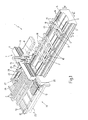
- Number 1 in Figure 1 indicates as a whole a machine for machining door and window frame component parts 2 of wood or similar, and which comprises an elongated, substantially U-shaped bed 3 extending in a horizontal direction 4 and having two lateral longitudinal members 5 extending parallel to direction 4 and each supporting a respective rail 6 also parallel to direction 4.
- Machine 1 also comprises a bridge 7, in turn comprising an upright 8 which is fitted in known manner to bed 3, is moved linearly in direction 4 along bed 3 by a known actuating device not shown, and is fitted on its free end with a cross member 9 extending over bed 3 in a horizontal direction 10 crosswise to direction 4, and bounded laterally by two opposite faces 11, 12 substantially perpendicular to direction 4.
- Bridge 7 supports a known machining head 13 which is fitted to face 11, is fitted in known manner to cross member 9 to move linearly along cross member 9 in direction 10, and comprises at least one tool spindle (not shown) fitted in known manner to head 13 to move in a vertical direction 14 perpendicular to directions 4 and 10.
- Machine 1 also comprises a number of cross members 15 - hereinafter referred to as "work surfaces” - which extend between rails 6 in direction 10, and are fitted to rails 6 to slide manually, or by means of respective known actuating devices not shown, along rails 6 in direction 4.
- Work surfaces 15 support a number of clamps 16, the arrangement of which on relative work surfaces 15 substantially depends on the size of, and the type of work to be carried out on, component parts 2.
- each clamp 16 comprises a fixed bottom jaw 17 fixed to relative work surface 15 and defining, with jaws 17 of the other clamps 16, a substantially horizontal supporting surface P1 for at least one component part 2; and a movable top jaw 18 which extends parallel to surface P1, is fitted to the free end of an output rod (not shown) of an actuating cylinder (not shown), and is moved by the actuating cylinder (not shown) between a clamped position ( Figure 1 ) and a release position respectively clamping and releasing component part 2.
- Machine 1 also comprises a feed device 19 for component parts 2, which comprises a bed 20 located alongside bed 3 in direction 4 and supporting a number of belt conveyors 21, which are aligned in direction 4, extend in respective vertical planes parallel to one another and to direction 10, and have respective coplanar top conveying branches defining a horizontal conveying surface P2 parallel to surface P1.
- a feed device 19 for component parts 2 which comprises a bed 20 located alongside bed 3 in direction 4 and supporting a number of belt conveyors 21, which are aligned in direction 4, extend in respective vertical planes parallel to one another and to direction 10, and have respective coplanar top conveying branches defining a horizontal conveying surface P2 parallel to surface P1.
- Conveyors 21 extend in direction 10 between a loading station 22 where component parts 2 for machining are loaded onto feed device 19, and an unloading station 23 where component parts 2 for machining are unloaded off feed device 19.
- Component parts 2 are transferred between clamps 16 and feed device 19 by a grip-and-carry assembly 24 comprising an arm 25, which projects in direction 4 from face 12 of cross member 9, is fitted in known manner to cross member 9 to move linearly along cross member 9 in direction 10 under the control of a known actuating device not shown, and is fitted, in the example shown, with two grip-and-carry devices 26, 27 movable with respect to each other in direction 4.
- a grip-and-carry assembly 24 comprising an arm 25, which projects in direction 4 from face 12 of cross member 9, is fitted in known manner to cross member 9 to move linearly along cross member 9 in direction 10 under the control of a known actuating device not shown, and is fitted, in the example shown, with two grip-and-carry devices 26, 27 movable with respect to each other in direction 4.
- device 26 is fixed to arm 25 in direction 4, while device 27 is fitted in known manner to arm 25 to move linearly along arm 25 in direction 4 under the control of a known actuating device not shown.
- each grip-and-carry device 26, 27 comprises a gripper, in turn comprising a substantially L-shaped bottom jaw 28 movable in direction 14 under the control of a known actuating device not shown; and a top jaw 29 which is fitted to the free end of an output rod 30 of an actuating cylinder 31 fixed to jaw 28, and is moved by actuating cylinder 31 between a grip position and a release position respectively gripping and releasing component part 2.
- component parts 2 are loaded successively onto feed device 19 at loading station 22, either manually or by means of a known loader not shown, are positioned contacting at least two known stops (not shown) located at loading station 22 to ensure each component part 2 is positioned correctly in direction 10, and are then fed successively in steps to unloading station 23.
- component parts 2 are loaded onto feed device 19, the component part 2 located at unloading station 23 is transferred by grip-and-carry assembly 24 to clamps 16 for machining by machining head 13, feed device 19 is operated to move another component part 2 into unloading station 23, and the machined component part 2 is transferred by assembly 24 from clamps 16 to loading station 22.
- the component part 2 unloaded at loading station 22 is then moved forward, behind the component parts 2 already unloaded at loading station 22 ( Figure 2 ), by a push device (not shown) operated independently of feed device 19 when device 19 is stopped.
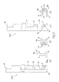
- the component part 2 for machining is picked up from station 23 by assembly 24; is inserted by assembly 24 inside at least one first clamp 16 (hereinafter indicated 16a) in an insertion direction 10a parallel to direction 10 ( Figure 3a ) to enable machining head 13 to machine a first side 2a of component part 2 ( Figure 3b ); is withdrawn from clamp 16a by assembly 24 ( Figure 3c ); and is inserted by assembly 24 inside at least one second clamp 16 (hereinafter indicated 16b) in an insertion direction 10b parallel to and opposite direction 10a, to enable machining head 13 to machine a second side 2b, opposite side 2a, of component part 2 ( Figure 3d ).
- component part 2 may be withdrawn from clamp 16a, moved in directions 10 and 14 onto the opposite side of clamp 16a, and inserted once more into the same clamp 16a in direction 10b to also machine side 2b.
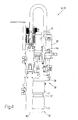
- grip-and-carry devices 26, 27 are replaced by respective dual grip-and-carry devices 32, 33, each comprising a respective slide 34, which is movable in direction 14 and supports two superimposed grippers 35, 36, with gripper 35 located over gripper 36.
- Gripper 35 comprises a bottom jaw 37 projecting in direction 10 from slide 34 and cooperating with a top jaw 38, which is movable in direction 14, with respect to slide 34 and under the control of an actuating cylinder 39 fixed to slide 34, between a grip position and a release position respectively gripping and releasing a first component part 2; and gripper 36 comprises a top jaw defined by bottom jaw 37 of gripper 35, and a bottom jaw 40, which is movable in direction 14, with respect to slide 34 and under the control of an actuating cylinder 41 fixed to slide 34, between a grip position and a release position respectively gripping and releasing a second component part 2.
- slide 34 of device 33 is in turn fitted to a slide (not shown) movable in direction 4 along arm 25.
- grip-and-carry assembly 24 in Figure 4 In actual use, at each operating cycle, grip-and-carry assembly 24 in Figure 4 :
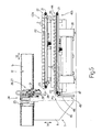
- feed device 19 is replaced by two feed devices 42, which are identical to device 19, define two parallel, superimposed supporting surfaces P2, and are located one (hereinafter indicated 42a) over the other (hereinafter indicated 42b).
- Device 42a extends between loading station 22 and unloading station 23, and successively feeds component parts 2 for machining from loading station 22 to unloading station 23; and device 42b feeds the machined component part 2 from an input station 43, projecting beyond unloading station 23 in direction 10, to an output station 44 opposite station 43 and located at loading station 22.
- device 42b is associated with a lifting device 45 comprising a substantially vertical supporting beam 46 facing bed 20 of devices 42a, 42b in direction 10; and a number of arms 47, which project from beam 46 in direction 10, are offset with respect to belt conveyors 21 of device 42b in direction 4, and define a supporting surface P3 for at least one machined component part 2.
- Beam 46 is movable in direction 14 between a raised position, in which device 45 receives the machined component part 2 from assembly 24, and a lowered position, in which arms 47 are positioned between conveyors 21, and surface P3 is positioned below surface P2 of device 42b.
- component parts 2 for machining are fed successively by device 42a from loading station 22 to unloading station 23, are picked up successively at station 23 by assembly 24, are transferred to clamps 16, and are machined by head 13.
- the machined component parts 2 are removed from clamps 16 by assembly 24, are released by assembly 24 onto surface P3 when device 45 is in the raised position, are lowered by device 45 at input station 43, are released by device 45 onto device 42b, and are fed by device 42b to output station 44.
- lifting device 45 may be eliminated, and the machined component parts 2 released directly by assembly 24 at input station 43 of device 42b.
- component parts 2 for machining may be loaded onto device 42a at station 22, and the machined component parts 2 unloaded off device 42b at station 44 either manually or automatically by means of respective feed devices, possibly associated with further machines identical to machine 1.
- bridge 7 supports machining head 13 only, and grip-and-carry assembly 24 is fitted to a further bridge identical to bridge 7.
Landscapes
- Engineering & Computer Science (AREA)
- Life Sciences & Earth Sciences (AREA)
- Mechanical Engineering (AREA)
- Wood Science & Technology (AREA)
- Forests & Forestry (AREA)
- Milling, Drilling, And Turning Of Wood (AREA)
- Feeding Of Workpieces (AREA)
- Chemical And Physical Treatments For Wood And The Like (AREA)
- Automatic Assembly (AREA)
- Door And Window Frames Mounted To Openings (AREA)
- Multi-Process Working Machines And Systems (AREA)
Claims (16)
- Procédé d'usinage d'articles (2) en bois ou similaire, en particulier de composants (2) de cadres de portes et fenêtres, sur une machine comprenant un tapis (3) s'étendant dans une première direction (4) ; au moins deux traverses (15) mobiles le long du tapis (3) dans la première direction (4) ; au moins un élément de serrage (16) équipant chaque traverse (15) pour serrer au moins un composant (2) à usiner ; un pont (7) ayant au moins une tête d'usinage (13) mobile le long du pont (7) dans une deuxième direction (10) transversale à la première direction (4) caractérisé en ce que le pont (7) se déplace le long du tapis (3) dans la première direction (4) ; un dispositif d'alimentation (19) pour l'alimentation des composants (2) par paliers entre une station de chargement (22) où les composants (2) à usiner sont chargés sur le dispositif d'alimentation (19), et une station de déchargement (23) où les composants (2) à usiner sont déchargés du dispositif d'alimentation (19) ; et un ensemble de saisie et de transport (24) pour saisir et transporter des composants (2), et qui est mobile dans lesdites première et deuxième directions (4, 10) ; le procédé comprenant les étapes qui consistent :à transférer au moins un composant (2) à usiner de la station de déchargement (23) jusqu'à au moins un élément de serrage (16) au moyen de l'ensemble de prise et de transport (24) ;à usiner le composant (2) ; età alimenter un autre composant (2) à usiner dans la station de déchargement (23) ;le procédé étant en outre caractérisé en ce qu'il comprend également l'étape qui consiste :à transférer le composant usiné (2) de l'élément de serrage (16) jusqu'à la station de chargement (22) au moyen de l'ensemble de prise et de transport (24).
- Procédé tel que revendiqué dans la revendication 1, et comprenant également les étapes qui consistent :à insérer, au moyen de l'ensemble de prise et de transport (24), le composant (2) à usiner dans au moins un élément de serrage (16) dans une première direction d'insertion (10a) ;à usiner un premier côté (2a) du composant (2) ;à retirer le composant (2) de l'élément de serrage (16) au moyen de l'ensemble de prise et de transport (24) ;à insérer le composant (2), au moyen de l'ensemble de prise et de transport (24), dans au moins un élément de serrage (16) dans une deuxième direction d'insertion (10b) opposée à la première direction d'insertion (10a) ; età usiner un deuxième côté (2b), opposé au premier côté (2a), du composant (2).
- Procédé tel que revendiqué dans la revendication 2, dans lequel le premier côté (2a) est usiné à l'intérieur d'au moins un élément de serrage (16a), et le deuxième côté (2b) est usiné à l'intérieur du même élément de serrage (16a).
- Procédé tel que revendiqué dans la revendication 2, dans lequel le premier côté (2a) est usiné à l'intérieur d'au moins un premier élément de serrage (16a), et le deuxième côté (2b) est usiné à l'intérieur d'au moins un deuxième élément de serrage (16b) différent du premier élément de serrage (16a).
- Procédé tel que revendiqué dans l'une quelconque des revendications précédentes, dans lequel l'ensemble de prise et de transport (24) comprend au moins deux dispositifs de prise et de transport (26, 27 ; 32, 33), chacun destiné à recevoir un composant relatif (2) ; le procédé comprenant également les étapes qui consistent :à retirer un composant usiné (2) d'au moins un élément de serrage (16) au moyen d'un premier desdits dispositifs de prise et de transport (26 ; 32) ;à insérer un composant (2) à usiner dans au moins un élément de serrage (16) au moyen d'un deuxième desdits dispositifs de prise et de transport (27 ; 33) ; età transférer le composant usinée (2) jusqu'à la station de chargement (22) au moyen du premier dispositif de prise et de transport (26 ; 32).
- Procédé tel que revendiqué dans la revendication 5, dans lequel les dispositifs de prise et de transport (32, 33) sont disposés de manière à définir deux surfaces de support essentiellement parallèles et superposées.
- Procédé tel que revendiqué dans l'une quelconque des revendications précédentes, dans lequel l'ensemble de prise et de transport (24) comprend un bras de support (25) s'étendant dans la première direction (4) ; et au moins deux dispositifs de prise et de transport (26, 27 ; 32, 33) mobiles le long du bras de support (25) dans la première direction (4) ; le procédé comprenant également l'étape qui consiste :à commander sélectivement la position des deux dispositifs de prise et de transport (26, 27 ; 32, 33) l'un par rapport à l'autre dans ladite première direction (4).
- Procédé tel que revendiqué dans l'une quelconque des revendications précédentes, dans lequel les éléments de serrage (16) sont fixés dans ladite deuxième direction (10).
- Procédé d'usinage d'articles (2) en bois ou similaire, en particulier de composants (2) de cadres de portes et fenêtres, sur une machine comprenant un tapis (3) s'étendant dans une première direction (4) ; au moins deux traverses (15) mobiles le long du tapis (3) dans la première direction (4) ; au moins un élément de serrage (16) équipant chaque traverse (15) pour serrer au moins un composant (2) à usiner ; un pont (7) ayant au moins une tête d'usinage (13) mobile le long du pont (7) dans une deuxième direction (10) transversale à la première direction (4) caractérisé en ce que le pont se déplace le long du tapis (3) dans la première direction (4) ; un premier dispositif d'alimentation (42a) pour l'alimentation des composants (2) par paliers entre une station de chargement (22) où les composants (2) à usiner sont chargés sur le dispositif d'alimentation (42a), et une station de déchargement (23) où les composants (2) à usiner sont déchargés du dispositif d'alimentation (42a) ; et un ensemble de prise et de transport (24) pour saisir et transporter les composants (2), et qui est mobile dans lesdites première et deuxième directions (4, 10) ; le procédé comprenant les étapes qui consistent :à transférer au moins un composant (2) à usiner de la station de déchargement (23) jusqu'à au moins un élément de serrage (16) au moyen de l'ensemble de prise et de transport (24) ; età usiner le composant (2) ;et le procédé étant en outre caractérisé en ce qu'il comprend également l'étape qui consiste :à transférer le composant usiné (2) de l'élément de serrage (16) jusqu'à une station d'entrée (43) d'un deuxième dispositif d'alimentation (42b) parallèle et superposé au premier dispositif d'alimentation (42a).
- Procédé tel que revendiqué dans la revendication 9, dans lequel le premier dispositif d'alimentation (42a) est placé sur le deuxième dispositif d'alimentation (42b).
- Procédé tel que revendiqué dans la revendication 9 ou 10, et comprenant également l'étape qui consiste :à transférer le composant usiné (2) de l'élément de serrage (16) jusqu'à la station d'entrée (43) au moyen de l'ensemble de prise et de transport (24).
- Procédé tel que revendiqué dans la revendication 9 ou 10, et comprenant également les étapes qui consistent :à transférer le composant usiné (2) de l'élément de serrage (16) jusqu'à un dispositif de levage (45) au moyen de l'ensemble de prise et de transport (24) ; età transférer le composant usiné (2) jusqu'à la station d'entrée (43) au moyen du dispositif de levage (45).
- Procédé tel que revendiqué dans la revendication 12, et comprenant également l'étape qui consiste à déplacer le dispositif de levage (45) vers et depuis une position de travail, où le dispositif de levage (45) se trouve pratiquement dans le même plan que le deuxième dispositif d'alimentation (42b).
- Procédé tel que revendiqué dans l'une quelconque des revendications 9 à 13, dans lequel le deuxième dispositif d'alimentation (42b) s'étend entre la station d'entrée (43) et une station de sortie (44) ; le procédé comprenant également l'étape qui consiste à alimenter le composant usiné (2) de la station d'entrée (43) jusqu'à la station de sortie (44) dans une première direction (4) parallèle et opposée à une deuxième direction (10) où le composant (2) à usiner est alimenté par la station de chargement (22) jusqu'à la station de déchargement (23).
- Procédé tel que revendiqué dans l'une quelconque des revendications 9 à 13, et comprenant également les étapes qui consistent à charger manuellement les composants (2) à usiner au niveau de la station de chargement (22), et à décharger manuellement les composants usinés (2) au niveau de la station de sortie (44).
- Procédé tel que revendiqué dans l'une quelconque des revendications 9 à 14, et comprenant en outre les étapes qui consistent à charger les composants (2) à usiner au niveau de la station de chargement (22), et à décharger les composants usinés (2) au niveau de la station de sortie (44) par l'intermédiaire de moyens d'alimentation automatiques.
Applications Claiming Priority (2)
| Application Number | Priority Date | Filing Date | Title |
|---|---|---|---|
| IT000356A ITBO20070356A1 (it) | 2007-05-14 | 2007-05-14 | Metodo per la lavorazione di componenti di legno o simili, in particolare componenti per infissi |
| EP07121372A EP1992464B1 (fr) | 2007-05-14 | 2007-11-22 | Méthode d'usinage d'un article en bois ou similaire, en particulier des composants de cadres de portes et fenêtres |
Related Parent Applications (1)
| Application Number | Title | Priority Date | Filing Date |
|---|---|---|---|
| EP07121372.2 Division | 2007-11-22 |
Publications (2)
| Publication Number | Publication Date |
|---|---|
| EP2241425A1 EP2241425A1 (fr) | 2010-10-20 |
| EP2241425B1 true EP2241425B1 (fr) | 2012-03-14 |
Family
ID=39639557
Family Applications (2)
| Application Number | Title | Priority Date | Filing Date |
|---|---|---|---|
| EP10172236A Active EP2241425B1 (fr) | 2007-05-14 | 2007-11-22 | Méthode d'usinage d'un article en bois ou similaire, en particulier des composants de cadres de portes et fenêtres |
| EP07121372A Active EP1992464B1 (fr) | 2007-05-14 | 2007-11-22 | Méthode d'usinage d'un article en bois ou similaire, en particulier des composants de cadres de portes et fenêtres |
Family Applications After (1)
| Application Number | Title | Priority Date | Filing Date |
|---|---|---|---|
| EP07121372A Active EP1992464B1 (fr) | 2007-05-14 | 2007-11-22 | Méthode d'usinage d'un article en bois ou similaire, en particulier des composants de cadres de portes et fenêtres |
Country Status (3)
| Country | Link |
|---|---|
| EP (2) | EP2241425B1 (fr) |
| AT (2) | ATE549142T1 (fr) |
| IT (1) | ITBO20070356A1 (fr) |
Families Citing this family (20)
| Publication number | Priority date | Publication date | Assignee | Title |
|---|---|---|---|---|
| ITBO20080140A1 (it) * | 2008-03-03 | 2009-09-04 | Biesse Spa | Metodo e macchina per la lavorazione di componenti di legno o simili |
| DE102008032302A1 (de) * | 2008-07-09 | 2010-01-14 | Weinmann Holzbausystemtechnik Gmbh | Vorrichtung zum Fördern eines Werkstücks |
| IT1391400B1 (it) * | 2008-09-02 | 2011-12-23 | Biesse Spa | Centro di lavoro per la lavorazione di componenti di legno o simili di forma allungata, in particolare componenti per infissi |
| WO2010041285A1 (fr) * | 2008-10-10 | 2010-04-15 | Working Process S.R.L. | Centre de travail |
| IT1408447B1 (it) * | 2010-10-21 | 2014-06-20 | Working Process S R L | Centro di lavoro con manipolatore perfezionato |
| IT1402597B1 (it) * | 2010-10-21 | 2013-09-13 | Working Process S R L | Centro di lavoro |
| IT1402782B1 (it) * | 2010-10-21 | 2013-09-18 | Working Process S R L | Centro di lavoro con piano di riscontro e raddrizzamento separato |
| DE102015212541A1 (de) * | 2014-09-22 | 2016-03-24 | Homag Holzbearbeitungssysteme Gmbh | Bearbeitungsvorrichtung |
| DE102014223910A1 (de) * | 2014-11-24 | 2016-05-25 | Homag Holzbearbeitungssysteme Gmbh | Werkstückzuführvorrichtung |
| DE102015204719A1 (de) * | 2015-03-16 | 2016-09-22 | Homag Holzbearbeitungssysteme Gmbh | Bearbeitungsvorrichtung |
| ITRN20150015A1 (it) * | 2015-04-22 | 2016-10-22 | Masterwood Spa | Centro di lavorazione automatico per componenti di infissi. |
| DE102015208618A1 (de) * | 2015-05-08 | 2016-11-10 | Homag Gmbh | Werkstückzuführvorrichtung bzw. Werkstückabführvorrichtung |
| DE102015218814A1 (de) | 2015-09-29 | 2017-03-30 | Homag Gmbh | Bearbeitungsvorrichtung |
| CN106625983A (zh) * | 2015-11-02 | 2017-05-10 | 东北林业大学 | 数控下回料两台封边机生产线 |
| CN106925804A (zh) * | 2017-04-07 | 2017-07-07 | 南兴装备股份有限公司 | 自动进出料自动扫条码的智能化通过式数控钻设备 |
| JP6704875B2 (ja) * | 2017-05-16 | 2020-06-03 | 株式会社平安コーポレーション | プレカット加工方法及びそのシステム |
| JP2020113293A (ja) * | 2020-02-27 | 2020-07-27 | 株式会社平安コーポレーション | プレカット加工方法及びそのシステム |
| EP3950217B1 (fr) * | 2020-08-03 | 2024-07-10 | F.O.M. Industrie S.r.l. | Procédé de configuration d'un poste de travail pour traiter des barres de section, fabriquées en particulier en aluminium, en alliages légers, en pvc ou analogues |
| EP3950218B1 (fr) * | 2020-08-03 | 2024-10-02 | F.O.M. Industrie S.r.l. | Centre de travail pour traiter des barres de section, en particulier en aluminium, en alliages légers, en pvc ou analogues |
| CN112705986A (zh) * | 2020-12-21 | 2021-04-27 | 常州工程职业技术学院 | 一种机械加工用自动化上料装置 |
Family Cites Families (8)
| Publication number | Priority date | Publication date | Assignee | Title |
|---|---|---|---|---|
| DE19503731A1 (de) * | 1995-02-04 | 1996-08-08 | Hans Hundegger | Abbundanlage zum Bearbeiten von Werkstücken, insbesondere Brettern, Kanthölzern und dergleichen |
| DE19733457C1 (de) * | 1997-08-02 | 1999-01-07 | Engelbert Guentert | Abbundanlage |
| DE19752685A1 (de) * | 1997-11-28 | 1999-07-01 | Ima Maschinenfabriken Klessmann Gmbh | Maschine zum Bearbeiten von Fensterrahmen-Holmen |
| IT1309312B1 (it) * | 1999-07-02 | 2002-01-22 | Biesse Spa | Impianto per la lavorazione di corpi piani. |
| IT1320885B1 (it) * | 2000-02-22 | 2003-12-10 | Biesse Spa | Macchina per la lavorazione di pannelli di legno o similari |
| ITBO20010643A1 (it) * | 2001-10-19 | 2003-04-19 | Impresa 2000 Di Sacchi Paride | Metodo e macchina per la lavorazione di componenti di legno o simili |
| ITMI20030247U1 (it) * | 2003-05-26 | 2004-11-27 | Celaschi S P A | Macchina per la lavorazione di elementi di infissi in legno |
| ITMO20060021A1 (it) * | 2006-01-20 | 2007-07-21 | Scm Group Spa | Macchina utensile |
-
2007
- 2007-05-14 IT IT000356A patent/ITBO20070356A1/it unknown
- 2007-11-22 AT AT10172236T patent/ATE549142T1/de active
- 2007-11-22 AT AT07121372T patent/ATE552953T1/de active
- 2007-11-22 EP EP10172236A patent/EP2241425B1/fr active Active
- 2007-11-22 EP EP07121372A patent/EP1992464B1/fr active Active
Also Published As
| Publication number | Publication date |
|---|---|
| EP1992464A3 (fr) | 2009-09-02 |
| ATE552953T1 (de) | 2012-04-15 |
| EP1992464A2 (fr) | 2008-11-19 |
| EP2241425A1 (fr) | 2010-10-20 |
| ATE549142T1 (de) | 2012-03-15 |
| ITBO20070356A1 (it) | 2008-11-15 |
| EP1992464B1 (fr) | 2012-04-11 |
Similar Documents
| Publication | Publication Date | Title |
|---|---|---|
| EP1992464B1 (fr) | Méthode d'usinage d'un article en bois ou similaire, en particulier des composants de cadres de portes et fenêtres | |
| EP1810803B1 (fr) | Machine pour l'usinage d'éléments constitués de bois avec chargement et déchargement automatiques desdits éléments et procédé de chargement desdits éléments | |
| CN106794594B (zh) | 加工装置 | |
| EP1810802A1 (fr) | Machine-outil | |
| AU2020217311B2 (en) | Processing machine for flat material parts with a support unit and method therefor | |
| CN101312805B (zh) | 机床 | |
| CN114786869B (zh) | 具有至少两个加工机器人的加工单元 | |
| EP2305440B1 (fr) | Procédé et appareil pour le traitement de composants en bois. | |
| EP2991811A1 (fr) | Centre d'usinage | |
| US11040426B2 (en) | Machine tool having a tool spindle and a loading portal | |
| EP2842705A1 (fr) | Procédé et machine pour traiter des composants en bois ou similaires | |
| JP2000515437A (ja) | 加工機 | |
| CN114453496A (zh) | 一种电动剃须刀刀片的冲压成型设备 | |
| EP1832402B1 (fr) | Moulurière pour mettre en forme longitudinalement des pièces de forme allongée en bois ou similaire, en particulier des parties de cadres de portes et fenêtres | |
| JP3650903B2 (ja) | トランスファ装置 | |
| EP1250213B1 (fr) | Machine-outil et procede d'usinage d'elements allonges, en particulier des elements profiles metalliques | |
| EP2098344B2 (fr) | Procédé et machine pour usiner des composants de bois ou similaire | |
| EP2025480A1 (fr) | Machine pour travailler de parties de portes et de fenêtres en bois ou similaire | |
| ITMO20100051A1 (it) | Apparato per la lavorazione di pezzi | |
| EP2105269A2 (fr) | Procédé et machine pour profiler des composants en bois allongé ou similaire, spécialement des composants pour les cadres de porte et de fenêtre | |
| EP2210723B1 (fr) | Machine et méthode pour le travail du bois ou de materiaux similaires | |
| EP4215327A1 (fr) | Machine de traitement de panneau et procédé de traitement de panneau avec ladite machine | |
| CN210125734U (zh) | 加工装置 | |
| CN220161817U (zh) | 夹具装置 | |
| JP2601408Y2 (ja) | 形鋼加工機 |
Legal Events
| Date | Code | Title | Description |
|---|---|---|---|
| PUAI | Public reference made under article 153(3) epc to a published international application that has entered the european phase |
Free format text: ORIGINAL CODE: 0009012 |
|
| AC | Divisional application: reference to earlier application |
Ref document number: 1992464 Country of ref document: EP Kind code of ref document: P |
|
| AK | Designated contracting states |
Kind code of ref document: A1 Designated state(s): AT BE BG CH CY CZ DE DK EE ES FI FR GB GR HU IE IS IT LI LT LU LV MC MT NL PL PT RO SE SI SK TR |
|
| 17P | Request for examination filed |
Effective date: 20110420 |
|
| RIC1 | Information provided on ipc code assigned before grant |
Ipc: B23Q 7/04 20060101ALI20110706BHEP Ipc: B27F 1/04 20060101ALI20110706BHEP Ipc: B27M 1/08 20060101AFI20110706BHEP |
|
| GRAP | Despatch of communication of intention to grant a patent |
Free format text: ORIGINAL CODE: EPIDOSNIGR1 |
|
| GRAS | Grant fee paid |
Free format text: ORIGINAL CODE: EPIDOSNIGR3 |
|
| GRAA | (expected) grant |
Free format text: ORIGINAL CODE: 0009210 |
|
| AC | Divisional application: reference to earlier application |
Ref document number: 1992464 Country of ref document: EP Kind code of ref document: P |
|
| AK | Designated contracting states |
Kind code of ref document: B1 Designated state(s): AT BE BG CH CY CZ DE DK EE ES FI FR GB GR HU IE IS IT LI LT LU LV MC MT NL PL PT RO SE SI SK TR |
|
| REG | Reference to a national code |
Ref country code: GB Ref legal event code: FG4D |
|
| REG | Reference to a national code |
Ref country code: AT Ref legal event code: REF Ref document number: 549142 Country of ref document: AT Kind code of ref document: T Effective date: 20120315 Ref country code: CH Ref legal event code: EP |
|
| REG | Reference to a national code |
Ref country code: IE Ref legal event code: FG4D |
|
| REG | Reference to a national code |
Ref country code: DE Ref legal event code: R096 Ref document number: 602007021389 Country of ref document: DE Effective date: 20120510 |
|
| REG | Reference to a national code |
Ref country code: NL Ref legal event code: VDEP Effective date: 20120314 |
|
| PG25 | Lapsed in a contracting state [announced via postgrant information from national office to epo] |
Ref country code: LT Free format text: LAPSE BECAUSE OF FAILURE TO SUBMIT A TRANSLATION OF THE DESCRIPTION OR TO PAY THE FEE WITHIN THE PRESCRIBED TIME-LIMIT Effective date: 20120314 |
|
| LTIE | Lt: invalidation of european patent or patent extension |
Effective date: 20120314 |
|
| PG25 | Lapsed in a contracting state [announced via postgrant information from national office to epo] |
Ref country code: FI Free format text: LAPSE BECAUSE OF FAILURE TO SUBMIT A TRANSLATION OF THE DESCRIPTION OR TO PAY THE FEE WITHIN THE PRESCRIBED TIME-LIMIT Effective date: 20120314 Ref country code: GR Free format text: LAPSE BECAUSE OF FAILURE TO SUBMIT A TRANSLATION OF THE DESCRIPTION OR TO PAY THE FEE WITHIN THE PRESCRIBED TIME-LIMIT Effective date: 20120615 Ref country code: LV Free format text: LAPSE BECAUSE OF FAILURE TO SUBMIT A TRANSLATION OF THE DESCRIPTION OR TO PAY THE FEE WITHIN THE PRESCRIBED TIME-LIMIT Effective date: 20120314 |
|
| PG25 | Lapsed in a contracting state [announced via postgrant information from national office to epo] |
Ref country code: CY Free format text: LAPSE BECAUSE OF FAILURE TO SUBMIT A TRANSLATION OF THE DESCRIPTION OR TO PAY THE FEE WITHIN THE PRESCRIBED TIME-LIMIT Effective date: 20120314 |
|
| PG25 | Lapsed in a contracting state [announced via postgrant information from national office to epo] |
Ref country code: BE Free format text: LAPSE BECAUSE OF FAILURE TO SUBMIT A TRANSLATION OF THE DESCRIPTION OR TO PAY THE FEE WITHIN THE PRESCRIBED TIME-LIMIT Effective date: 20120314 Ref country code: RO Free format text: LAPSE BECAUSE OF FAILURE TO SUBMIT A TRANSLATION OF THE DESCRIPTION OR TO PAY THE FEE WITHIN THE PRESCRIBED TIME-LIMIT Effective date: 20120314 Ref country code: IS Free format text: LAPSE BECAUSE OF FAILURE TO SUBMIT A TRANSLATION OF THE DESCRIPTION OR TO PAY THE FEE WITHIN THE PRESCRIBED TIME-LIMIT Effective date: 20120714 Ref country code: EE Free format text: LAPSE BECAUSE OF FAILURE TO SUBMIT A TRANSLATION OF THE DESCRIPTION OR TO PAY THE FEE WITHIN THE PRESCRIBED TIME-LIMIT Effective date: 20120314 Ref country code: SI Free format text: LAPSE BECAUSE OF FAILURE TO SUBMIT A TRANSLATION OF THE DESCRIPTION OR TO PAY THE FEE WITHIN THE PRESCRIBED TIME-LIMIT Effective date: 20120314 Ref country code: SE Free format text: LAPSE BECAUSE OF FAILURE TO SUBMIT A TRANSLATION OF THE DESCRIPTION OR TO PAY THE FEE WITHIN THE PRESCRIBED TIME-LIMIT Effective date: 20120314 Ref country code: CZ Free format text: LAPSE BECAUSE OF FAILURE TO SUBMIT A TRANSLATION OF THE DESCRIPTION OR TO PAY THE FEE WITHIN THE PRESCRIBED TIME-LIMIT Effective date: 20120314 Ref country code: PL Free format text: LAPSE BECAUSE OF FAILURE TO SUBMIT A TRANSLATION OF THE DESCRIPTION OR TO PAY THE FEE WITHIN THE PRESCRIBED TIME-LIMIT Effective date: 20120314 |
|
| PG25 | Lapsed in a contracting state [announced via postgrant information from national office to epo] |
Ref country code: SK Free format text: LAPSE BECAUSE OF FAILURE TO SUBMIT A TRANSLATION OF THE DESCRIPTION OR TO PAY THE FEE WITHIN THE PRESCRIBED TIME-LIMIT Effective date: 20120314 Ref country code: PT Free format text: LAPSE BECAUSE OF FAILURE TO SUBMIT A TRANSLATION OF THE DESCRIPTION OR TO PAY THE FEE WITHIN THE PRESCRIBED TIME-LIMIT Effective date: 20120716 |
|
| PLBE | No opposition filed within time limit |
Free format text: ORIGINAL CODE: 0009261 |
|
| STAA | Information on the status of an ep patent application or granted ep patent |
Free format text: STATUS: NO OPPOSITION FILED WITHIN TIME LIMIT |
|
| PG25 | Lapsed in a contracting state [announced via postgrant information from national office to epo] |
Ref country code: NL Free format text: LAPSE BECAUSE OF FAILURE TO SUBMIT A TRANSLATION OF THE DESCRIPTION OR TO PAY THE FEE WITHIN THE PRESCRIBED TIME-LIMIT Effective date: 20120314 Ref country code: DK Free format text: LAPSE BECAUSE OF FAILURE TO SUBMIT A TRANSLATION OF THE DESCRIPTION OR TO PAY THE FEE WITHIN THE PRESCRIBED TIME-LIMIT Effective date: 20120314 |
|
| 26N | No opposition filed |
Effective date: 20121217 |
|
| PG25 | Lapsed in a contracting state [announced via postgrant information from national office to epo] |
Ref country code: IT Free format text: LAPSE BECAUSE OF FAILURE TO SUBMIT A TRANSLATION OF THE DESCRIPTION OR TO PAY THE FEE WITHIN THE PRESCRIBED TIME-LIMIT Effective date: 20120314 |
|
| REG | Reference to a national code |
Ref country code: DE Ref legal event code: R097 Ref document number: 602007021389 Country of ref document: DE Effective date: 20121217 |
|
| PG25 | Lapsed in a contracting state [announced via postgrant information from national office to epo] |
Ref country code: ES Free format text: LAPSE BECAUSE OF FAILURE TO SUBMIT A TRANSLATION OF THE DESCRIPTION OR TO PAY THE FEE WITHIN THE PRESCRIBED TIME-LIMIT Effective date: 20120625 |
|
| REG | Reference to a national code |
Ref country code: CH Ref legal event code: PL |
|
| GBPC | Gb: european patent ceased through non-payment of renewal fee |
Effective date: 20121122 |
|
| PG25 | Lapsed in a contracting state [announced via postgrant information from national office to epo] |
Ref country code: BG Free format text: LAPSE BECAUSE OF FAILURE TO SUBMIT A TRANSLATION OF THE DESCRIPTION OR TO PAY THE FEE WITHIN THE PRESCRIBED TIME-LIMIT Effective date: 20120614 Ref country code: CH Free format text: LAPSE BECAUSE OF NON-PAYMENT OF DUE FEES Effective date: 20121130 Ref country code: LI Free format text: LAPSE BECAUSE OF NON-PAYMENT OF DUE FEES Effective date: 20121130 |
|
| REG | Reference to a national code |
Ref country code: IE Ref legal event code: MM4A |
|
| REG | Reference to a national code |
Ref country code: FR Ref legal event code: ST Effective date: 20130731 |
|
| PG25 | Lapsed in a contracting state [announced via postgrant information from national office to epo] |
Ref country code: IE Free format text: LAPSE BECAUSE OF NON-PAYMENT OF DUE FEES Effective date: 20121122 |
|
| PG25 | Lapsed in a contracting state [announced via postgrant information from national office to epo] |
Ref country code: MT Free format text: LAPSE BECAUSE OF FAILURE TO SUBMIT A TRANSLATION OF THE DESCRIPTION OR TO PAY THE FEE WITHIN THE PRESCRIBED TIME-LIMIT Effective date: 20120314 Ref country code: FR Free format text: LAPSE BECAUSE OF NON-PAYMENT OF DUE FEES Effective date: 20121130 Ref country code: GB Free format text: LAPSE BECAUSE OF NON-PAYMENT OF DUE FEES Effective date: 20121122 |
|
| PG25 | Lapsed in a contracting state [announced via postgrant information from national office to epo] |
Ref country code: MC Free format text: LAPSE BECAUSE OF NON-PAYMENT OF DUE FEES Effective date: 20121130 Ref country code: TR Free format text: LAPSE BECAUSE OF FAILURE TO SUBMIT A TRANSLATION OF THE DESCRIPTION OR TO PAY THE FEE WITHIN THE PRESCRIBED TIME-LIMIT Effective date: 20120314 |
|
| PG25 | Lapsed in a contracting state [announced via postgrant information from national office to epo] |
Ref country code: LU Free format text: LAPSE BECAUSE OF NON-PAYMENT OF DUE FEES Effective date: 20121122 |
|
| PG25 | Lapsed in a contracting state [announced via postgrant information from national office to epo] |
Ref country code: HU Free format text: LAPSE BECAUSE OF FAILURE TO SUBMIT A TRANSLATION OF THE DESCRIPTION OR TO PAY THE FEE WITHIN THE PRESCRIBED TIME-LIMIT Effective date: 20071122 |
|
| PGFP | Annual fee paid to national office [announced via postgrant information from national office to epo] |
Ref country code: DE Payment date: 20251126 Year of fee payment: 19 |
|
| PGFP | Annual fee paid to national office [announced via postgrant information from national office to epo] |
Ref country code: AT Payment date: 20251118 Year of fee payment: 19 |