EP2241489A2 - Mécanisme de direction sans pincement - Google Patents
Mécanisme de direction sans pincement Download PDFInfo
- Publication number
- EP2241489A2 EP2241489A2 EP10250784A EP10250784A EP2241489A2 EP 2241489 A2 EP2241489 A2 EP 2241489A2 EP 10250784 A EP10250784 A EP 10250784A EP 10250784 A EP10250784 A EP 10250784A EP 2241489 A2 EP2241489 A2 EP 2241489A2
- Authority
- EP
- European Patent Office
- Prior art keywords
- pair
- steering mechanism
- cross member
- attached
- tongue
- Prior art date
- Legal status (The legal status is an assumption and is not a legal conclusion. Google has not performed a legal analysis and makes no representation as to the accuracy of the status listed.)
- Withdrawn
Links
- 230000007246 mechanism Effects 0.000 title claims description 53
- 210000002105 tongue Anatomy 0.000 description 29
- 229910000831 Steel Inorganic materials 0.000 description 3
- 239000010959 steel Substances 0.000 description 3
- 230000009471 action Effects 0.000 description 2
- 239000000463 material Substances 0.000 description 2
- 239000004033 plastic Substances 0.000 description 2
- 230000008901 benefit Effects 0.000 description 1
- 230000004048 modification Effects 0.000 description 1
- 238000012986 modification Methods 0.000 description 1
- 239000002023 wood Substances 0.000 description 1
Images






Classifications
-
- B—PERFORMING OPERATIONS; TRANSPORTING
- B62—LAND VEHICLES FOR TRAVELLING OTHERWISE THAN ON RAILS
- B62B—HAND-PROPELLED VEHICLES, e.g. HAND CARTS OR PERAMBULATORS; SLEDGES
- B62B3/00—Hand carts having more than one axis carrying transport wheels; Steering devices therefor; Equipment therefor
- B62B3/001—Steering devices
-
- B—PERFORMING OPERATIONS; TRANSPORTING
- B62—LAND VEHICLES FOR TRAVELLING OTHERWISE THAN ON RAILS
- B62B—HAND-PROPELLED VEHICLES, e.g. HAND CARTS OR PERAMBULATORS; SLEDGES
- B62B3/00—Hand carts having more than one axis carrying transport wheels; Steering devices therefor; Equipment therefor
- B62B3/007—Coaster wagons
-
- B—PERFORMING OPERATIONS; TRANSPORTING
- B62—LAND VEHICLES FOR TRAVELLING OTHERWISE THAN ON RAILS
- B62B—HAND-PROPELLED VEHICLES, e.g. HAND CARTS OR PERAMBULATORS; SLEDGES
- B62B2301/00—Wheel arrangements; Steering; Stability; Wheel suspension
- B62B2301/04—Wheel arrangements; Steering; Stability; Wheel suspension comprising a wheel pivotable about a substantially vertical axis, e.g. swivelling castors
-
- B—PERFORMING OPERATIONS; TRANSPORTING
- B62—LAND VEHICLES FOR TRAVELLING OTHERWISE THAN ON RAILS
- B62B—HAND-PROPELLED VEHICLES, e.g. HAND CARTS OR PERAMBULATORS; SLEDGES
- B62B5/00—Accessories or details specially adapted for hand carts
- B62B5/0006—Bumpers; Safety devices
-
- B—PERFORMING OPERATIONS; TRANSPORTING
- B62—LAND VEHICLES FOR TRAVELLING OTHERWISE THAN ON RAILS
- B62B—HAND-PROPELLED VEHICLES, e.g. HAND CARTS OR PERAMBULATORS; SLEDGES
- B62B5/00—Accessories or details specially adapted for hand carts
- B62B5/06—Hand moving equipment, e.g. handle bars
- B62B5/067—Stowable or retractable handle bars
Definitions
- the present invention relates generally to children's vehicles and, more particularly, to a steering mechanism for children's vehicles such as wagons.
- Children's wagons have long been popular play items. They often feature a body constructed of steel, plastic or wood that includes a floor surrounded by sidewalls so that cargo may be hauled. Alternatively, a child may sit or kneel on the floor of the wagon.
- a pair of rear wheels are typically mounted to the underside of the rear portion of the wagon floor while a bolster is pivotally mounted in the fashion of a turntable to the underside of the front portion of the wagon floor.
- a pair of front wheels are mounted to the bolster as is a pivoting handle.
- the wagon may be pulled by the handle which may also be used to steer the front wheels by pivoting the bolster.
- the handle may also be rotated back towards the rear of the wagon so that the handle may be accessed by a wagon passenger when the wagon is used "coaster" style.
- Such wagons may only be pivoted a limited amount to protect against tipping the wagon during turning.
- such wagons are typically constructed with a "limited turning" feature, such as the one illustrated in U.S. Patent No. 4,744,575 to Tonelli .
- a disadvantage of including this feature is that the wagon has a larger turning radius. This makes the wagon more difficult to maneuver.
- such wagons may be difficult to turn, especially on rough surfaces, as each of the front wheels must traverse an arc as the bolster pivots during turning.
- FIG. 1A An example of such a steering mechanism is illustrated in Figs. 1A through 1C , where the wagon handle is pivotally attached to tongue 20. While such a mechanism functions well when the wagon is traveling generally straight forward, as illustrated in Fig. 1A , a pinching hazard exists when the wagon is turned, as illustrated in Figs. 1B and 1C . More specifically, as illustrated in Fig. 1B , as the wagon is turned, one of the mechanism torque arms 22 pivots towards cross member 24. In addition, the tie rod 26 moves toward the cross member 24. As illustrated in Fig.
- a steering mechanism for a children's vehicle comprising:
- the steering mechanism may further comprise a mount connected to the cross member and adapted to be attached to the children's vehicle.
- the tongue assembly may include a lower tongue and an upper tongue that may be connected together by their leading portions and trailing portions, said upper tongue may be pivotally connected to the mount and said low tongue may be pivotally connected to the cross member.
- the steering mechanism may further comprise a disk-shaped pinch shield attached to the cross member at a pivotal connection between the lower tongue and the cross member.
- the steering mechanism may further comprise a disk-shaped pinch shield attached to the upper tongue, said disk-shaped pinch shield pivotally connected to the mount.
- the steering mechanism may further comprise a clevis attached to the leading portion of the tongue assembly and pivotally attached to said handle.
- the steering mechanism may further comprise a pair of bearings positioned one each at opposite ends of the cross member; and wherein the pair of axle spindles may be generally L-shaped and each may include a generally vertical portion and a generally horizontal portion, with the vertical portions pivotally received one each by the pair of bearings and the pair of wheels rotatably mounted one each on the horizontal portions.
- Each vertical portion of the pair of axle spindles may feature a squared fitting that is engaged by one of the pair of generally S-shaped torque arms.
- the pair of generally S-shaped torque arms may each include a central portion, each of said pair of generally S-shaped torque arms may be sized and shaped so that a distance between the central portion of each torque arm and the tie rod is never less than approximately 12.0 mm.
- the cross member may feature a generally inverted U-shape so that said handle may be pivoted into a storage position under the vehicle.
- the steering mechanism may be attached to a children's vehicle.
- the children's vehicle may comprise a body and the steering mechanism may be attached to the body via the cross member.
- the body may be a wagon body and the cross member may be mounted to an underside of a floor of the wagon body.
- a vehicle comprising a steering mechanism according to the first aspect of the invention.
- a vehicle comprising:
- Figs. 1A-1B are bottom perspective views of a prior art wagon steering mechanism as it is actuated
- Fig. 2 is a perspective view of an embodiment of the steering mechanism of the present invention attached to a wagon body;
- Figs. 3A-3C are enlarged perspective views of the steering mechanism of Fig. 2 configured to direct the wagon straight, in a maximum right turn and in a maximum left turn, respectively;
- Fig. 4 is a bottom perspective view of the steering mechanism of Fig. 3C ;
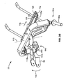
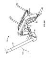
- Figs. 5A and 5B show steering mechanism of Figs. 2-4 with the handle in a use position and a storage position, respectively;
- Fig. 6 is a perspective view of a wagon equipped with the steering mechanism of Figs. 2-5B with the handle in the storage position of Fig. 5B .
- steering mechanism of the present invention is described below in terms of a children's wagon, it is to be understood that the steering mechanism of the invention may be used on other types of wagons and children's vehicles.
- An embodiment of the steering mechanism of the present invention is indicated in general at 32 in Fig. 2 and attached to the bottom of the body, indicated in general at 34, of a children's wagon.
- the body 34 may be constructed of steel, plastic, wood or any other durable rigid material and preferably features a floor 36 surrounded by a continuous sidewall 38.
- a handle is pivotally attached by its bottom end to the steering mechanism 32, as explained in greater detail below, and features a handgrip 44 at the top end.
- the handle may pivoted in the direction of arrow 46 from the "pulling" position illustrated in Fig. 2 to a "coaster wagon” position where the handle may be accessed by a child positioned in the wagon.
- the handle may be pivoted in the opposite direction into a storage position under the wagon body.
- a pair of front wheels 48a and 48b may be attached to the steering mechanism while a pairs of rear wheels 52a and 52b may be mounted to the underside of the rear portion of the wagon floor of the wagon body.
- the steering mechanism 32 includes a tongue assembly, indicated in general at 54.
- the tongue assembly includes a lower tongue 55 with a leading end that terminates in clevis 56.
- the lower tongue 55 and clevis 56 may be manufactured as a single piece or as multiple pieces that are attached together.
- the clevis 56 receives the bottom end of the wagon handle 42 in a pivotal fashion via a bolt or screw that passes through openings 58a and 58b ( Fig. 3A ).
- An upper tongue, indicated in general at 62 in Fig. 3A is attached by its leading end portion 64 to the clevis 56.
- the upper tongue 62 features leading and trailing ramp portions 66 and 68, respectively, that are secured to disk-shaped pinch shield 70.
- the upper tongue and pinch shield may be formed as a single piece.
- Pinch shield 70 is pivotally attached to the underside of the central portion 72 of a steering mechanism mount, indicated in general at 74 in Fig. 3A . More specifically, the underside of the central portion 72 features a bore (not shown) that receives a rivet, bolt or screw that passes through an opening formed in the center of the pinch shield 70.
- the steering mechanism mount 74 features downward extending leg portions 76a and 76b.
- the end portions of a cross member 82 are secured to the bottom ends of the steering mechanism mount legs 76a and 76b.
- the cross member 82 features a generally inverted U-shape and features a horizontal central portion 84.
- the central portion of lower tongue 55 is pivotally attached via a fastener such as a nut and bolt, screw or rivet to the underside of the horizontal central portion 84 of the cross member 82 (see also Fig. 4 ).
- a disk-shaped pinch shield 86 is mounted to the top side of the horizontal central portion of the cross member.
- Support braces 90a and 90b are also attached by their lower ends to the cross member 82.
- the upper ends of the support braces are secured to the underside of the wagon floor (36 in Fig. 2 ).
- the connections may be made by rivets, nuts and bolts, welds or other fastening arrangements known in the art.
- each axle spindle vertical portion is provided with a squared fitting, illustrated for spindle 94b at 96b in Fig. 3A and at 96a in Fig. 4 for spindle 94a.
- Each axle spindle also features a horizontal portion illustrated at 98a and 98b. As illustrated in Fig. 6 , each horizontal portion receives a front wheel of the wagon. As illustrated in Figs.
- each axle spindle is also provided with upper washers 102a and 102b and lower washers 104a and 104b which engage annular grooves formed in the vertical portions of the axle spindle so that each is secured within its respective bearing.
- the horizontal portions 98a and 98b are provided with flanges 106a and 106b to limit inward travel of the wagon front wheels mounted thereon.
- the wagon front wheels may be secured on the horizontal portions 98a and 98b by pressure-fit axle caps, illustrated at 107a and 107b in Fig. 2 .
- the trailing ends of the upper and lower tongues are pivotally connected to the central portion of a tie rod 108 by a fastener (which may be a bolt, screw, rivet or the like).
- the ends of generally S-shaped torque arms 112a and 112b are pivotally connected one each to the opposing ends of the tie rod 108.
- the other ends of the S-shaped torque arms feature square openings which engage the squared fittings 96a ( Fig. 4 ) and 96b ( Fig. 3A ) of the axle spindles.
- All of the components of the steering mechanism described above are preferably constructed from steel. Other high-strength and rigid materials may alternatively be used.
- the steering mechanism 32 features the configuration of Figs. 2 and 3A when the wagon is being steered straight forward or backward by handle 42.
- the steering mechanism is configured as illustrated in Fig. 3B . More specifically, with reference to Fig. 3B , when the clevis 56 is moved in the direction of arrow 114 (via the handle 42 of Fig. 2 ), the tongue assembly pivots clockwise about axis 116 (illustrated in phantom) so that the trailing end of the tongue assembly, and thus tie rod 108, moves in the direction of arrow 118.
- the movement of tie rod 108 causes torque arms 112a and 112b to pivot clockwise about the vertical portions of axle spindles 94a and 94b.
- the horizontal portions of the axle spindles 98a and 98b, and thus the wagon front wheels also pivot clockwise about the vertical portions of axle spindles 94a and 94b so that the wagon turns.
- the steering mechanism is configured as illustrated in Figs. 3C and 4 . More specifically, as is apparent from the above paragraph, the tongue assembly pivots counterclockwise about axis 116 ( Fig. 3C ) when the clevis 56 is moved in the direction of arrow 122 (via the handle 42 of Fig. 2 ) so that tie rod 108 moves in the direction of arrow 124. This causes the torque arms 112a and 112b to pivot counterclockwise about the vertical portions of axle spindles 94a and 94b. As a result, the horizontal portions of the axle spindles 98a and 98b, and thus the wagon front wheels, also pivot counterclockwise about the vertical portions of axle spindles 94a and 94b so that the wagon turns.
- the shape of the torque arms 112a and 112b prevent the occurrence of "scissor" actions and thus pinch points between the tie rod 108 and the torque arms 112a and 112b when the wagon is steered in a sharp right or left turn.
- the generally S-shaped torque arm 112a causes a space 126 to be formed between the torque arm 112a and the tie rod 108.
- the space 126 is sized so that the distance between the central portion 128a of the torque arm 112a and the tie rod 108, indicated at 130 in Fig. 3B , is at least approximately 12.0 mm.
- the generally S-shaped torque arm 112b causes a space 132 to be formed between the torque arm 112b and the tie rod 108.
- the space 132 is sized so that the distance between the central portion 128b of the torque arm 112b and the tie rod 108, indicated at 134 in Fig. 4 , is at least approximately 12.0 mm. This prevents children's fingers from being pinched in the steering mechanism.
- Figs. 5A , 5B and 6 illustrate a further benefit of the steering mechanism 32 of Figs. 1-4 .
- the wagon handle 42 may pivot from a use position, such as the one illustrated in Fig. 5A , in the direction of arrow 136 to the storage position illustrated in Figs. 5B and 6 , where the handle is positioned beneath the wagon body 34 ( Fig. 6 ).
- the generally inverted U-shape of cross member 82 permits the handle to pass under the horizontal central portion 84 to a position adjacent to the wagon body. This permits the wagon to assume a compact configuration for ease of loading, transport and/or storage.
Landscapes
- Engineering & Computer Science (AREA)
- Chemical & Material Sciences (AREA)
- Combustion & Propulsion (AREA)
- Transportation (AREA)
- Mechanical Engineering (AREA)
- Carriages For Children, Sleds, And Other Hand-Operated Vehicles (AREA)
- Steering-Linkage Mechanisms And Four-Wheel Steering (AREA)
- Handcart (AREA)
- Toys (AREA)
Applications Claiming Priority (1)
| Application Number | Priority Date | Filing Date | Title |
|---|---|---|---|
| US12/424,912 US8020880B2 (en) | 2009-04-16 | 2009-04-16 | No-pinch steering mechanism |
Publications (2)
| Publication Number | Publication Date |
|---|---|
| EP2241489A2 true EP2241489A2 (fr) | 2010-10-20 |
| EP2241489A3 EP2241489A3 (fr) | 2011-11-02 |
Family
ID=42320532
Family Applications (1)
| Application Number | Title | Priority Date | Filing Date |
|---|---|---|---|
| EP10250784A Withdrawn EP2241489A3 (fr) | 2009-04-16 | 2010-04-15 | Mécanisme de direction sans pincement |
Country Status (6)
| Country | Link |
|---|---|
| US (1) | US8020880B2 (fr) |
| EP (1) | EP2241489A3 (fr) |
| JP (1) | JP5647431B2 (fr) |
| CN (1) | CN101863281B (fr) |
| CA (1) | CA2700156A1 (fr) |
| TW (1) | TW201040058A (fr) |
Families Citing this family (12)
| Publication number | Priority date | Publication date | Assignee | Title |
|---|---|---|---|---|
| US11788650B1 (en) | 2019-02-22 | 2023-10-17 | Santiva Outdoors, L.L.C. | Outdoor apparatus |
| US11008030B2 (en) * | 2019-02-22 | 2021-05-18 | Santiva Outdoors, L.L.C.—Series Ip | Adaptable modular attachment and accessory system for use with coolers, bait buckets and other containers |
| IT1396073B1 (it) * | 2009-10-01 | 2012-11-09 | Co Ge Car S N C Di Montano & Sanvido | Carrello di trasporto per impianti industriali |
| CN103661540B (zh) * | 2013-12-17 | 2016-02-24 | 于法周 | 一种旋转式车轮推柄 |
| US9187109B2 (en) * | 2014-04-01 | 2015-11-17 | Active Products Inc. | Folding travel wagon |
| CN105946945A (zh) * | 2016-05-09 | 2016-09-21 | 苏州先锋物流装备科技有限公司 | 一种转向系统 |
| CN109795602A (zh) * | 2019-01-22 | 2019-05-24 | 平湖市小明星儿童用品有限公司 | 一种童车的转向辅助件 |
| CN214325200U (zh) * | 2020-06-29 | 2021-10-01 | 宁波脉趣贸易有限公司 | 一种儿童手推车 |
| CN112722046A (zh) * | 2020-12-29 | 2021-04-30 | 李志强 | 一种混凝土试块养护搬运装置 |
| CN113212510A (zh) * | 2021-05-28 | 2021-08-06 | 永嘉县吉明水泵有限公司 | 一种立式多级泵维修装置 |
| USD1094462S1 (en) | 2021-12-23 | 2025-09-23 | Imperial Industrial Supply Co. | Portable generator frame |
| USD1086631S1 (en) * | 2025-04-09 | 2025-07-29 | Xincan Technology (Hangzhou) Co., LTD | Wagon |
Citations (1)
| Publication number | Priority date | Publication date | Assignee | Title |
|---|---|---|---|---|
| US4744575A (en) | 1986-06-30 | 1988-05-17 | Radio Steel & Mfg. Co. | Coaster wagon with anti-tipping features |
Family Cites Families (39)
| Publication number | Priority date | Publication date | Assignee | Title |
|---|---|---|---|---|
| US678144A (en) * | 1900-09-17 | 1901-07-09 | Thomas B Jeffery | Carriage-steering mechanism. |
| US781238A (en) * | 1904-09-07 | 1905-01-31 | Clement Smith | Steering apparatus for motor-vehicles. |
| US810679A (en) * | 1905-03-07 | 1906-01-23 | George K Rudert | Steering device for vehicles. |
| US1131254A (en) * | 1914-09-09 | 1915-03-09 | Charles A Longman | Child's and toy wagon. |
| US1156023A (en) * | 1914-09-28 | 1915-10-05 | Kirk Latty Mfg Company | Combined front gear and steering connection for children's vehicles. |
| US1197581A (en) * | 1915-10-18 | 1916-09-05 | Int Motor Co | Steering mechanism for motor-vehicles. |
| US1550049A (en) * | 1922-12-15 | 1925-08-18 | George W Rundle | Bolster for children's vehicles |
| US2542433A (en) * | 1948-08-09 | 1951-02-20 | Walter H Rockman | Coaster wagon |
| US2913250A (en) * | 1957-09-18 | 1959-11-17 | Nathan C Hale | Toy wagon steering and braking system |
| US3066945A (en) * | 1961-04-24 | 1962-12-04 | Prescott Wilmar Lewis | Steerable hand cart |
| US3295622A (en) * | 1965-01-13 | 1967-01-03 | Arthur H Pitchford | Steerable load-carrying vehicle |
| US3315976A (en) * | 1965-03-22 | 1967-04-25 | William E Thiermann | Two wheel dolly |
| US3430975A (en) * | 1967-02-08 | 1969-03-04 | Lloyd J Wolf | Trailer steering arrangement |
| US3477742A (en) * | 1968-03-13 | 1969-11-11 | Robert W Barrington | Wear compensating bearings for trailer hitch |
| US3608659A (en) * | 1969-04-07 | 1971-09-28 | Norman S Gardner | Motorized golf cart |
| US3695628A (en) * | 1970-07-01 | 1972-10-03 | James C Fisher | Farm wagon steering stabilizer |
| CA960243A (en) * | 1974-03-05 | 1974-12-31 | Marcel Houle | Wagon for transporting an erected scaffold |
| US4098519A (en) * | 1977-07-18 | 1978-07-04 | Reid Jr Thomas J | Wheeled sled |
| US4222582A (en) * | 1978-09-18 | 1980-09-16 | Radio Steel & Mfg. Co. | Coaster wagon with safety cap |
| US4192525A (en) * | 1978-09-22 | 1980-03-11 | Clarke-Gravely Corporation | Steering sulky for two-wheel tractors |
| US4655467A (en) * | 1985-03-19 | 1987-04-07 | Airstream, Inc. | Steerable torsion axle |
| US5340142A (en) * | 1993-03-10 | 1994-08-23 | E-Z Trail, Inc. | Towing tongue assembly |
| FR2707277B1 (fr) * | 1993-07-05 | 1995-10-06 | Aerospatiale | Train amovible pour le roulage directif d'une charge. |
| JPH08326446A (ja) * | 1995-05-31 | 1996-12-10 | Tateyama Alum Ind Co Ltd | 伸縮リンク |
| US6079721A (en) * | 1997-07-18 | 2000-06-27 | Brown Manufacturing Corporation | Steering mechanism for non-riding ground engaging equipment |
| WO1999019198A1 (fr) * | 1997-10-15 | 1999-04-22 | Igc (Australia) Pty. Ltd. | Ensemble porte-charge a deplacement dirige |
| US5947493A (en) * | 1997-12-04 | 1999-09-07 | Radio Flyer, Inc. | Children's wagon front bolster |
| US6158759A (en) * | 1998-11-02 | 2000-12-12 | Perry; Duane L. | Wagon steering control mechanism |
| US6186524B1 (en) * | 1999-02-16 | 2001-02-13 | Radio Flyer, Inc. | Children's wagon with improved bolster |
| US6601860B2 (en) * | 2000-04-10 | 2003-08-05 | Angie Potter | Wagon for use in a hospital |
| US6302421B1 (en) * | 2000-05-15 | 2001-10-16 | Aaron Lee | Vehicle with swivel control of casters for enabling rider or external steering |
| DE20121758U1 (de) * | 2000-06-30 | 2003-04-17 | BEBECAR Utilidades para Criança Lda., Caldas de Sao Jorge | Verbundschwenksystem mit eingebauter Aufhängung für Kinderwagen |
| US6325403B1 (en) * | 2000-07-19 | 2001-12-04 | Wayne A. Brutger | Helicopter dolly |
| US6641149B2 (en) * | 2001-08-27 | 2003-11-04 | Radio Flyer Inc. | Children's wagon with improved removable walls |
| US6619680B2 (en) * | 2001-10-30 | 2003-09-16 | Wellmaster Pipe And Supply Inc. | Agricultural wagon having all-wheel steering |
| US7114732B1 (en) * | 2003-11-21 | 2006-10-03 | Jeffery A Ismail | All-terrain welding cart |
| JP2007245843A (ja) * | 2006-03-15 | 2007-09-27 | Hitachi Ltd | ステアリング装置のタイロッド構造 |
| CN201102563Y (zh) * | 2007-09-29 | 2008-08-20 | 好孩子儿童用品有限公司 | 童车防夹手结构 |
| US7926833B2 (en) * | 2009-09-14 | 2011-04-19 | Hellbusch James A | All-wheels steer trailer |
-
2009
- 2009-04-16 US US12/424,912 patent/US8020880B2/en not_active Expired - Fee Related
-
2010
- 2010-04-14 JP JP2010092886A patent/JP5647431B2/ja not_active Expired - Fee Related
- 2010-04-15 CA CA2700156A patent/CA2700156A1/fr not_active Abandoned
- 2010-04-15 EP EP10250784A patent/EP2241489A3/fr not_active Withdrawn
- 2010-04-16 TW TW099112006A patent/TW201040058A/zh unknown
- 2010-04-16 CN CN201010163626.6A patent/CN101863281B/zh not_active Expired - Fee Related
Patent Citations (1)
| Publication number | Priority date | Publication date | Assignee | Title |
|---|---|---|---|---|
| US4744575A (en) | 1986-06-30 | 1988-05-17 | Radio Steel & Mfg. Co. | Coaster wagon with anti-tipping features |
Also Published As
| Publication number | Publication date |
|---|---|
| TW201040058A (en) | 2010-11-16 |
| US8020880B2 (en) | 2011-09-20 |
| JP2010247827A (ja) | 2010-11-04 |
| US20100264625A1 (en) | 2010-10-21 |
| CN101863281B (zh) | 2015-05-20 |
| EP2241489A3 (fr) | 2011-11-02 |
| CN101863281A (zh) | 2010-10-20 |
| CA2700156A1 (fr) | 2010-10-16 |
| JP5647431B2 (ja) | 2014-12-24 |
Similar Documents
| Publication | Publication Date | Title |
|---|---|---|
| EP2241489A2 (fr) | Mécanisme de direction sans pincement | |
| US12503147B2 (en) | Tip limiting member for wheeled cart and assemblies thereof | |
| US6554298B1 (en) | Steerable load-carrying assemblies | |
| US8413999B2 (en) | Wheeled apparatus having multiple wheelbase configurations | |
| US6499750B1 (en) | Wagon with improved handle attachment arrangement | |
| WO1994018049A1 (fr) | Voiture-jouet | |
| US9623778B2 (en) | Transport system | |
| EP2528799A1 (fr) | Chariot à plate-formes, muni d'une plate-forme pouvant basculer vers le haut de deux côtés | |
| NL1042519B1 (nl) | Multifunctionele transportinrichting, rijwiel voorzien daarvan en werkwijze daarvoor | |
| US7316413B2 (en) | Steering mechanism for wheelbarrow | |
| US8562003B2 (en) | Cart brake and cart with user-operable brake | |
| US7011485B2 (en) | Tiltable hand truck | |
| NL1017961C1 (nl) | Kinderwagen met bestuurbare wielen. | |
| US20140334904A1 (en) | Dump cart | |
| HK1145307A (en) | No-pinch steering mechanism | |
| DE10257932B4 (de) | Hankkarren | |
| JP2003104208A (ja) | ブレーキ付き手押運搬車 | |
| DE41249C (de) | Neuerung an Fahrrädern | |
| NL1015809C2 (nl) | Kinderwagen met bestuurbare wielen. | |
| AU750530B2 (en) | Steering system | |
| CN2196577Y (zh) | 多功能变形小推车 | |
| AU746765B2 (en) | Steerable load-carrying assemblies | |
| DE202023107436U1 (de) | Fahrradanhänger und Gespann | |
| EP4370401A2 (fr) | Porteur de charges roulant à entraînement électrique, système de commande et/ou de régulation de porteur de charges roulant, procédé de commande et/ou de régulation d'un porteur de charges roulant à commande électrique et produit-programme informatique pour mettre en oeuvre ledit procédé au moyen d'un ordinateur | |
| CN110422210A (zh) | 一种布料运输车 |
Legal Events
| Date | Code | Title | Description |
|---|---|---|---|
| PUAI | Public reference made under article 153(3) epc to a published international application that has entered the european phase |
Free format text: ORIGINAL CODE: 0009012 |
|
| AK | Designated contracting states |
Kind code of ref document: A2 Designated state(s): AT BE BG CH CY CZ DE DK EE ES FI FR GB GR HR HU IE IS IT LI LT LU LV MC MK MT NL NO PL PT RO SE SI SK SM TR |
|
| AX | Request for extension of the european patent |
Extension state: AL BA ME RS |
|
| PUAL | Search report despatched |
Free format text: ORIGINAL CODE: 0009013 |
|
| AK | Designated contracting states |
Kind code of ref document: A3 Designated state(s): AT BE BG CH CY CZ DE DK EE ES FI FR GB GR HR HU IE IS IT LI LT LU LV MC MK MT NL NO PL PT RO SE SI SK SM TR |
|
| AX | Request for extension of the european patent |
Extension state: AL BA ME RS |
|
| RIC1 | Information provided on ipc code assigned before grant |
Ipc: B62B 3/00 20060101AFI20110928BHEP |
|
| 17P | Request for examination filed |
Effective date: 20120109 |
|
| RIC1 | Information provided on ipc code assigned before grant |
Ipc: B62B 5/00 20060101ALI20130812BHEP Ipc: B62B 3/00 20060101AFI20130812BHEP Ipc: B62B 5/06 20060101ALI20130812BHEP |
|
| GRAP | Despatch of communication of intention to grant a patent |
Free format text: ORIGINAL CODE: EPIDOSNIGR1 |
|
| INTG | Intention to grant announced |
Effective date: 20130927 |
|
| STAA | Information on the status of an ep patent application or granted ep patent |
Free format text: STATUS: THE APPLICATION IS DEEMED TO BE WITHDRAWN |
|
| 18D | Application deemed to be withdrawn |
Effective date: 20131101 |