EP2241752A2 - Système de pompe - Google Patents
Système de pompe Download PDFInfo
- Publication number
- EP2241752A2 EP2241752A2 EP10170292A EP10170292A EP2241752A2 EP 2241752 A2 EP2241752 A2 EP 2241752A2 EP 10170292 A EP10170292 A EP 10170292A EP 10170292 A EP10170292 A EP 10170292A EP 2241752 A2 EP2241752 A2 EP 2241752A2
- Authority
- EP
- European Patent Office
- Prior art keywords
- pump
- pump system
- rotary drive
- pump unit
- drive device
- Prior art date
- Legal status (The legal status is an assumption and is not a legal conclusion. Google has not performed a legal analysis and makes no representation as to the accuracy of the status listed.)
- Granted
Links
- 238000005086 pumping Methods 0.000 title claims abstract 3
- 230000005540 biological transmission Effects 0.000 claims abstract description 12
- 239000012530 fluid Substances 0.000 claims abstract description 5
- 238000011010 flushing procedure Methods 0.000 claims abstract 2
- 238000005553 drilling Methods 0.000 claims description 6
- 230000008878 coupling Effects 0.000 claims description 3
- 238000010168 coupling process Methods 0.000 claims description 3
- 238000005859 coupling reaction Methods 0.000 claims description 3
- 239000007788 liquid Substances 0.000 description 4
- 238000005520 cutting process Methods 0.000 description 2
- 230000000712 assembly Effects 0.000 description 1
- 238000000429 assembly Methods 0.000 description 1
- 238000005461 lubrication Methods 0.000 description 1
- 238000000034 method Methods 0.000 description 1
Images

Classifications
-
- F—MECHANICAL ENGINEERING; LIGHTING; HEATING; WEAPONS; BLASTING
- F04—POSITIVE - DISPLACEMENT MACHINES FOR LIQUIDS; PUMPS FOR LIQUIDS OR ELASTIC FLUIDS
- F04B—POSITIVE-DISPLACEMENT MACHINES FOR LIQUIDS; PUMPS
- F04B1/00—Multi-cylinder machines or pumps characterised by number or arrangement of cylinders
- F04B1/005—Pumps with cylinder axis arranged substantially tangentially to a circle centred on main shaft axis
-
- F—MECHANICAL ENGINEERING; LIGHTING; HEATING; WEAPONS; BLASTING
- F04—POSITIVE - DISPLACEMENT MACHINES FOR LIQUIDS; PUMPS FOR LIQUIDS OR ELASTIC FLUIDS
- F04B—POSITIVE-DISPLACEMENT MACHINES FOR LIQUIDS; PUMPS
- F04B9/00—Piston machines or pumps characterised by the driving or driven means to or from their working members
- F04B9/02—Piston machines or pumps characterised by the driving or driven means to or from their working members the means being mechanical
-
- E—FIXED CONSTRUCTIONS
- E21—EARTH OR ROCK DRILLING; MINING
- E21B—EARTH OR ROCK DRILLING; OBTAINING OIL, GAS, WATER, SOLUBLE OR MELTABLE MATERIALS OR A SLURRY OF MINERALS FROM WELLS
- E21B21/00—Methods or apparatus for flushing boreholes, e.g. by use of exhaust air from motor
- E21B21/08—Controlling or monitoring pressure or flow of drilling fluid, e.g. automatic filling of boreholes, automatic control of bottom pressure
-
- F—MECHANICAL ENGINEERING; LIGHTING; HEATING; WEAPONS; BLASTING
- F01—MACHINES OR ENGINES IN GENERAL; ENGINE PLANTS IN GENERAL; STEAM ENGINES
- F01C—ROTARY-PISTON OR OSCILLATING-PISTON MACHINES OR ENGINES
- F01C21/00—Component parts, details or accessories not provided for in groups F01C1/00 - F01C20/00
- F01C21/007—General arrangements of parts; Frames and supporting elements
-
- F—MECHANICAL ENGINEERING; LIGHTING; HEATING; WEAPONS; BLASTING
- F04—POSITIVE - DISPLACEMENT MACHINES FOR LIQUIDS; PUMPS FOR LIQUIDS OR ELASTIC FLUIDS
- F04B—POSITIVE-DISPLACEMENT MACHINES FOR LIQUIDS; PUMPS
- F04B17/00—Pumps characterised by combination with, or adaptation to, specific driving engines or motors
- F04B17/03—Pumps characterised by combination with, or adaptation to, specific driving engines or motors driven by electric motors
-
- F—MECHANICAL ENGINEERING; LIGHTING; HEATING; WEAPONS; BLASTING
- F04—POSITIVE - DISPLACEMENT MACHINES FOR LIQUIDS; PUMPS FOR LIQUIDS OR ELASTIC FLUIDS
- F04C—ROTARY-PISTON, OR OSCILLATING-PISTON, POSITIVE-DISPLACEMENT MACHINES FOR LIQUIDS; ROTARY-PISTON, OR OSCILLATING-PISTON, POSITIVE-DISPLACEMENT PUMPS
- F04C15/00—Component parts, details or accessories of machines, pumps or pumping installations, not provided for in groups F04C2/00 - F04C14/00
- F04C15/0057—Driving elements, brakes, couplings, transmission specially adapted for machines or pumps
- F04C15/0061—Means for transmitting movement from the prime mover to driven parts of the pump, e.g. clutches, couplings, transmissions
Definitions
- the invention relates to a pump system for conveying rinsing fluid during propulsion or when drilling holes, with a pump unit and with a rotary drive device for driving the pump unit.
- the drilling fluid is supplied to the bore during the drilling process.
- the rinsing liquid serves on the one hand for the lubrication of the working at the working face or on the hole sole drilling tools and the support of the working face or the bore wall.
- the rinsing liquid and dissolved cuttings are brought out of the hole in which, for example centrally through a hollow drill string fresh rinse liquid in the area of the borehole bottom or the working face is supplied and thus a rinsing liquid flow is generated, entrains the dissolved cuttings and from the Bring out bore.
- Particularly powerful pump systems are required to generate the rinsing fluid flow required for dispensing.
- the delivery rate of such pump systems is regularly in the range of a maximum of 3000 l / min and a maximum pressure of 500 bar.
- the invention is therefore based on the object to provide a pump system which does not have the aforementioned disadvantages.
- the rotary drive means via a drive and a driven gear comprehensive gear transmission is operatively connected to the pump unit, which is a chain drive own noise is avoided. Furthermore, it has surprisingly been found that it is sufficient for the transmission of the power and torques required for the operation of the pump unit to provide a gear transmission only on one side of the pump system.
- an embodiment of the pump system according to the invention is particularly preferred, in which the rotary drive device has only a single shaft end, with which the drive wheel is preferably wooverbindbar via a coupling.
- the noise level produced by the gear transmission can be further reduced if, as is particularly preferred, the gears of the gear transmission are helically toothed.
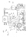
- the pump system 100 comprises a pump unit 1 of conventional design.
- This pump unit 1 comprises a housing 2, from whose side facing the observer one end of a pump drive shaft 3 protrudes. With this shaft end the driven gear 4 of a gear transmission 5 is rotatably connected.
- the gear transmission 5 serves to produce the operative connection of the pump assembly with a rotary drive device 6, which comprises a rotation motor R, which is indicated only in the drawing, for example hydraulically or electrically driven.
- the rotary drive device 6 comprises a housing 7, which is flanged to the housing 2 of the pump unit 1.
- a shaft end of a driven shaft 8 projects out of the housing 7 of the rotary drive device 6. It is connected via a clutch 12 with a drive wheel 9, which selectively rotatably connects or disconnects the drive wheel 9 with the shaft end.
- the drive wheel 9 is coupled to the output gear 4 via an intermediate gear 10, which is rotatably mounted in a housing 11 of the gear transmission.
- an elastic, non-shiftable coupling can be provided, which permanently connects the shaft end with the drive wheel.
- the teeth of the idler gear 10 is in engagement with the teeth of the drive wheel 9 and the output gear 4.
- the wheels of the gear transmission are helically toothed.
Landscapes
- Engineering & Computer Science (AREA)
- Mechanical Engineering (AREA)
- General Engineering & Computer Science (AREA)
- Geology (AREA)
- Life Sciences & Earth Sciences (AREA)
- Mining & Mineral Resources (AREA)
- General Life Sciences & Earth Sciences (AREA)
- Fluid Mechanics (AREA)
- Environmental & Geological Engineering (AREA)
- Geochemistry & Mineralogy (AREA)
- Physics & Mathematics (AREA)
- Details And Applications Of Rotary Liquid Pumps (AREA)
- Rotary Pumps (AREA)
- Fluid-Driven Valves (AREA)
- Eye Examination Apparatus (AREA)
- Reciprocating Pumps (AREA)
Applications Claiming Priority (3)
| Application Number | Priority Date | Filing Date | Title |
|---|---|---|---|
| DE102005016884A DE102005016884A1 (de) | 2005-04-12 | 2005-04-12 | Pumpensystem |
| EP06707001.1A EP1869284B1 (fr) | 2005-04-12 | 2006-02-16 | Systeme de pompe |
| PCT/EP2006/001400 WO2006108466A1 (fr) | 2005-04-12 | 2006-02-16 | Systeme de pompe |
Related Parent Applications (3)
| Application Number | Title | Priority Date | Filing Date |
|---|---|---|---|
| EP06707001.1 Division | 2006-02-16 | ||
| EP06707001.1A Division-Into EP1869284B1 (fr) | 2005-04-12 | 2006-02-16 | Systeme de pompe |
| EP06707001.1A Division EP1869284B1 (fr) | 2005-04-12 | 2006-02-16 | Systeme de pompe |
Publications (4)
| Publication Number | Publication Date |
|---|---|
| EP2241752A2 true EP2241752A2 (fr) | 2010-10-20 |
| EP2241752A3 EP2241752A3 (fr) | 2015-12-09 |
| EP2241752B1 EP2241752B1 (fr) | 2019-06-12 |
| EP2241752B2 EP2241752B2 (fr) | 2022-07-20 |
Family
ID=36354140
Family Applications (2)
| Application Number | Title | Priority Date | Filing Date |
|---|---|---|---|
| EP10170292.6A Ceased EP2241752B2 (fr) | 2005-04-12 | 2006-02-16 | Système de pompe |
| EP06707001.1A Revoked EP1869284B1 (fr) | 2005-04-12 | 2006-02-16 | Systeme de pompe |
Family Applications After (1)
| Application Number | Title | Priority Date | Filing Date |
|---|---|---|---|
| EP06707001.1A Revoked EP1869284B1 (fr) | 2005-04-12 | 2006-02-16 | Systeme de pompe |
Country Status (7)
| Country | Link |
|---|---|
| US (1) | US8186977B2 (fr) |
| EP (2) | EP2241752B2 (fr) |
| CN (1) | CN101160446B (fr) |
| DE (1) | DE102005016884A1 (fr) |
| NO (1) | NO343827B1 (fr) |
| RU (1) | RU2392414C2 (fr) |
| WO (1) | WO2006108466A1 (fr) |
Families Citing this family (4)
| Publication number | Priority date | Publication date | Assignee | Title |
|---|---|---|---|---|
| US8920146B2 (en) * | 2005-04-12 | 2014-12-30 | Mhwirth Gmbh | Pump system |
| EP2362116B1 (fr) * | 2010-02-18 | 2017-02-01 | Grundfos Management A/S | Roue dentée ainsi qu'agrégat de pompe doté d'une telle roue dentée |
| JP5934543B2 (ja) * | 2012-03-29 | 2016-06-15 | Kyb株式会社 | 流体圧駆動ユニット |
| GB2585681B (en) | 2019-07-11 | 2022-04-06 | Mhwirth As | Drilling rig systems |
Citations (4)
| Publication number | Priority date | Publication date | Assignee | Title |
|---|---|---|---|---|
| GB1034058A (en) | 1964-05-21 | 1966-06-29 | William Stewart Robinson | Improvements in sun-and-planet gearing |
| US20040028540A1 (en) | 1998-10-01 | 2004-02-12 | Peck Julian Claude | Manually operated pump or compressor |
| US20040060717A1 (en) | 2002-09-30 | 2004-04-01 | Jarmo Leppanen | Drilling rig having a compact compressor/pump assembly |
| US20040219040A1 (en) | 2003-04-30 | 2004-11-04 | Vladimir Kugelev | Direct drive reciprocating pump |
Family Cites Families (17)
| Publication number | Priority date | Publication date | Assignee | Title |
|---|---|---|---|---|
| US2899247A (en) * | 1959-08-11 | Feed water pump | ||
| US879560A (en) * | 1905-10-05 | 1908-02-18 | Daniel F Lepley | Triplex pump. |
| US2131749A (en) * | 1936-06-29 | 1938-10-04 | Homestead Valve Mfg Co | Pump |
| US2331513A (en) * | 1937-12-18 | 1943-10-12 | Emsco Derrick & Equip Co | Slush pump |
| US2755739A (en) * | 1953-07-20 | 1956-07-24 | Lever Brothers Ltd | Proportioning pump |
| US2883874A (en) * | 1958-02-03 | 1959-04-28 | Halliburton Oil Well Cementing | Heavy duty pump |
| US4118151A (en) * | 1974-04-03 | 1978-10-03 | Tokico Ltd. | Pump device |
| US4009971A (en) * | 1974-06-07 | 1977-03-01 | Binks Manufacturing Company | Electric motor-driven, double-acting pump having pressure-responsive actuation |
| US4435990A (en) * | 1980-09-11 | 1984-03-13 | Chalmers Samuel A | Power take off gear box |
| CA1205327A (fr) * | 1981-12-04 | 1986-06-03 | Gordon M. Sommer | Entrainement pour pompe sur forage |
| US5246355A (en) | 1992-07-10 | 1993-09-21 | Special Projects Manufacturing, Inc. | Well service pumping assembly |
| RU5224U1 (ru) * | 1997-02-26 | 1997-10-16 | Андрей Петрович Донодин | Насосный агрегат |
| RU2146777C1 (ru) * | 1998-08-12 | 2000-03-20 | Валерий Николаевич Петрухин | Насосный агрегат |
| CN2385075Y (zh) * | 1999-08-23 | 2000-06-28 | 石油地球物理勘探局装备制造总厂 | 石油地质勘探钻机用泥浆泵 |
| CN2612816Y (zh) * | 2003-03-30 | 2004-04-21 | 泰安市水利机械厂 | 高压柱塞泥浆泵 |
| US20040213677A1 (en) * | 2003-04-24 | 2004-10-28 | Matzner Mark D. | Monitoring system for reciprocating pumps |
| US7404704B2 (en) | 2003-04-30 | 2008-07-29 | S.P.M. Flow Control, Inc. | Manifold assembly for reciprocating pump |
-
2005
- 2005-04-12 DE DE102005016884A patent/DE102005016884A1/de not_active Ceased
-
2006
- 2006-02-16 WO PCT/EP2006/001400 patent/WO2006108466A1/fr not_active Ceased
- 2006-02-16 EP EP10170292.6A patent/EP2241752B2/fr not_active Ceased
- 2006-02-16 CN CN2006800120030A patent/CN101160446B/zh not_active Expired - Fee Related
- 2006-02-16 EP EP06707001.1A patent/EP1869284B1/fr not_active Revoked
- 2006-02-16 US US11/918,310 patent/US8186977B2/en active Active
- 2006-02-16 RU RU2007141682/03A patent/RU2392414C2/ru active
-
2007
- 2007-10-09 NO NO20075108A patent/NO343827B1/no unknown
Patent Citations (4)
| Publication number | Priority date | Publication date | Assignee | Title |
|---|---|---|---|---|
| GB1034058A (en) | 1964-05-21 | 1966-06-29 | William Stewart Robinson | Improvements in sun-and-planet gearing |
| US20040028540A1 (en) | 1998-10-01 | 2004-02-12 | Peck Julian Claude | Manually operated pump or compressor |
| US20040060717A1 (en) | 2002-09-30 | 2004-04-01 | Jarmo Leppanen | Drilling rig having a compact compressor/pump assembly |
| US20040219040A1 (en) | 2003-04-30 | 2004-11-04 | Vladimir Kugelev | Direct drive reciprocating pump |
Non-Patent Citations (1)
| Title |
|---|
| BEITZ W. ET AL: "DUBBEL - TASCHENBUCH FÜR DEN MASCHINENBAU", 1990, SPRINGER-VERLAG, pages: 115 - 117, XP003023378 |
Also Published As
| Publication number | Publication date |
|---|---|
| EP1869284B1 (fr) | 2018-12-26 |
| EP2241752A3 (fr) | 2015-12-09 |
| CN101160446B (zh) | 2013-07-03 |
| CN101160446A (zh) | 2008-04-09 |
| NO20075108L (no) | 2007-11-07 |
| EP1869284A1 (fr) | 2007-12-26 |
| RU2392414C2 (ru) | 2010-06-20 |
| RU2007141682A (ru) | 2009-05-20 |
| DE102005016884A1 (de) | 2006-10-19 |
| NO343827B1 (no) | 2019-06-17 |
| US20090038852A1 (en) | 2009-02-12 |
| EP2241752B1 (fr) | 2019-06-12 |
| EP2241752B2 (fr) | 2022-07-20 |
| WO2006108466A1 (fr) | 2006-10-19 |
| US8186977B2 (en) | 2012-05-29 |
Similar Documents
| Publication | Publication Date | Title |
|---|---|---|
| DE60219033T2 (de) | Spülrohranordnung | |
| EP0866210B1 (fr) | Méthode d'actionnement d'un outil et dispositif pour la transmission de couple et de vitesse de rotation d'un organe d'entraínement vers cet outil | |
| EP0324870B1 (fr) | Tube de trains de tiges autoguidés pour trains de tiges de machines de forage de roche | |
| DE19581945B4 (de) | Antriebskopf für eine Bohrlochpumpe | |
| DE60207109T2 (de) | Flüssigkeitsgetriebene bohrloch-bohrmaschine | |
| EP2241752A2 (fr) | Système de pompe | |
| DE2824441C2 (de) | Erdbohrer | |
| DE1946400A1 (de) | Bohrvorrichtung,insbesondere fuer schwache und mittlere Tiefen | |
| DE112013004544T5 (de) | Antriebseinheit für Kettenantriebe im Bergbau | |
| DE2733199A1 (de) | Bohrvorrichtung zum einbringen von tiefbohrungen in erdreich, gestein u.dgl. | |
| DE4113986A1 (de) | Hydraulisch angetriebener bohrmotor zum tiefbohren | |
| DE102011109330B4 (de) | Steuerbare Bohrvorrichtung | |
| DE4402487A1 (de) | Kompaktbohreinheit für gegenläufiges Überlagerungsbohren auf Kleinbohrgeräten | |
| DE102008034083B4 (de) | Erdbohrvorrichtung | |
| DE330888C (de) | Tragbare Antriebsmaschine | |
| DE19617213C1 (de) | Biegestabverbindung | |
| AU2022200150B2 (en) | Arrangement of a ground drilling device, method for operating a ground drilling device and use of an arrangement of a ground drilling device | |
| AT510314B1 (de) | Schneidvorrichtung für verfahrbare abbaumaschinen für den unterwassereinsatz | |
| DE389505C (de) | Einrichtung zum Foerdern von Erdoel, Sole und anderen Fluessigkeiten aus Bohrloechern | |
| EP4606987A1 (fr) | Dispositif pour percer des trous de forage au moyen d'un système de forage | |
| DE9110496U1 (de) | Bohrgerät | |
| DE3130762A1 (de) | Swabwinde zur verwendung bei der erdoel- bzw. erdgasfoerderung | |
| DE600536C (de) | Selbsttaetige hydraulische Nachlassvorrichtung fuer das Rotarybohren | |
| AT211764B (de) | Hydraulische Turbine für Drehbohrantriebe in Tiefbohrlöchern und Verfahren zu ihrem Betrieb | |
| AT244264B (de) | Vorrichtung und Verfahren zum Niederbringen eines Bohrloches |
Legal Events
| Date | Code | Title | Description |
|---|---|---|---|
| PUAI | Public reference made under article 153(3) epc to a published international application that has entered the european phase |
Free format text: ORIGINAL CODE: 0009012 |
|
| AC | Divisional application: reference to earlier application |
Ref document number: 1869284 Country of ref document: EP Kind code of ref document: P |
|
| AK | Designated contracting states |
Kind code of ref document: A2 Designated state(s): DE IT |
|
| TPAC | Observations filed by third parties |
Free format text: ORIGINAL CODE: EPIDOSNTIPA |
|
| RAP1 | Party data changed (applicant data changed or rights of an application transferred) |
Owner name: MHWIRTH GMBH |
|
| PUAL | Search report despatched |
Free format text: ORIGINAL CODE: 0009013 |
|
| RIC1 | Information provided on ipc code assigned before grant |
Ipc: E21B 21/08 20060101AFI20151020BHEP |
|
| AK | Designated contracting states |
Kind code of ref document: A3 Designated state(s): DE IT |
|
| TPAC | Observations filed by third parties |
Free format text: ORIGINAL CODE: EPIDOSNTIPA |
|
| 17P | Request for examination filed |
Effective date: 20160607 |
|
| RBV | Designated contracting states (corrected) |
Designated state(s): DE IT |
|
| 17Q | First examination report despatched |
Effective date: 20160914 |
|
| STAA | Information on the status of an ep patent application or granted ep patent |
Free format text: STATUS: EXAMINATION IS IN PROGRESS |
|
| TPAC | Observations filed by third parties |
Free format text: ORIGINAL CODE: EPIDOSNTIPA |
|
| TPAC | Observations filed by third parties |
Free format text: ORIGINAL CODE: EPIDOSNTIPA |
|
| GRAP | Despatch of communication of intention to grant a patent |
Free format text: ORIGINAL CODE: EPIDOSNIGR1 |
|
| STAA | Information on the status of an ep patent application or granted ep patent |
Free format text: STATUS: GRANT OF PATENT IS INTENDED |
|
| INTG | Intention to grant announced |
Effective date: 20190104 |
|
| GRAS | Grant fee paid |
Free format text: ORIGINAL CODE: EPIDOSNIGR3 |
|
| GRAA | (expected) grant |
Free format text: ORIGINAL CODE: 0009210 |
|
| STAA | Information on the status of an ep patent application or granted ep patent |
Free format text: STATUS: THE PATENT HAS BEEN GRANTED |
|
| AC | Divisional application: reference to earlier application |
Ref document number: 1869284 Country of ref document: EP Kind code of ref document: P |
|
| AK | Designated contracting states |
Kind code of ref document: B1 Designated state(s): DE IT |
|
| REG | Reference to a national code |
Ref country code: DE Ref legal event code: R096 Ref document number: 502006016271 Country of ref document: DE |
|
| REG | Reference to a national code |
Ref country code: DE Ref legal event code: R026 Ref document number: 502006016271 Country of ref document: DE |
|
| PLBI | Opposition filed |
Free format text: ORIGINAL CODE: 0009260 |
|
| PLAX | Notice of opposition and request to file observation + time limit sent |
Free format text: ORIGINAL CODE: EPIDOSNOBS2 |
|
| 26 | Opposition filed |
Opponent name: BENTEC GMBH DRILLING & OILFIELD SYSTEMS Effective date: 20200310 |
|
| PLBB | Reply of patent proprietor to notice(s) of opposition received |
Free format text: ORIGINAL CODE: EPIDOSNOBS3 |
|
| RIC2 | Information provided on ipc code assigned after grant |
Ipc: F04C 15/00 20060101ALI20210818BHEP Ipc: F04B 9/02 20060101ALI20210818BHEP Ipc: F01C 21/00 20060101ALI20210818BHEP Ipc: E21B 21/08 20060101AFI20210818BHEP |
|
| PUAH | Patent maintained in amended form |
Free format text: ORIGINAL CODE: 0009272 |
|
| STAA | Information on the status of an ep patent application or granted ep patent |
Free format text: STATUS: PATENT MAINTAINED AS AMENDED |
|
| 27A | Patent maintained in amended form |
Effective date: 20220720 |
|
| AK | Designated contracting states |
Kind code of ref document: B2 Designated state(s): DE IT |
|
| REG | Reference to a national code |
Ref country code: DE Ref legal event code: R102 Ref document number: 502006016271 Country of ref document: DE |
|
| PGFP | Annual fee paid to national office [announced via postgrant information from national office to epo] |
Ref country code: IT Payment date: 20230103 Year of fee payment: 18 Ref country code: DE Payment date: 20230104 Year of fee payment: 18 |
|
| REG | Reference to a national code |
Ref country code: DE Ref legal event code: R119 Ref document number: 502006016271 Country of ref document: DE |
|
| PG25 | Lapsed in a contracting state [announced via postgrant information from national office to epo] |
Ref country code: DE Free format text: LAPSE BECAUSE OF NON-PAYMENT OF DUE FEES Effective date: 20240903 |
|
| PG25 | Lapsed in a contracting state [announced via postgrant information from national office to epo] |
Ref country code: DE Free format text: LAPSE BECAUSE OF NON-PAYMENT OF DUE FEES Effective date: 20240903 |
|
| PG25 | Lapsed in a contracting state [announced via postgrant information from national office to epo] |
Ref country code: IT Free format text: LAPSE BECAUSE OF NON-PAYMENT OF DUE FEES Effective date: 20240216 |