EP2241771A2 - Linear axis - Google Patents
Linear axis Download PDFInfo
- Publication number
- EP2241771A2 EP2241771A2 EP10159624A EP10159624A EP2241771A2 EP 2241771 A2 EP2241771 A2 EP 2241771A2 EP 10159624 A EP10159624 A EP 10159624A EP 10159624 A EP10159624 A EP 10159624A EP 2241771 A2 EP2241771 A2 EP 2241771A2
- Authority
- EP
- European Patent Office
- Prior art keywords
- guide
- brake
- wedge
- linear axis
- guide rail
- Prior art date
- Legal status (The legal status is an assumption and is not a legal conclusion. Google has not performed a legal analysis and makes no representation as to the accuracy of the status listed.)
- Granted
Links
Images




Classifications
-
- F—MECHANICAL ENGINEERING; LIGHTING; HEATING; WEAPONS; BLASTING
- F16—ENGINEERING ELEMENTS AND UNITS; GENERAL MEASURES FOR PRODUCING AND MAINTAINING EFFECTIVE FUNCTIONING OF MACHINES OR INSTALLATIONS; THERMAL INSULATION IN GENERAL
- F16C—SHAFTS; FLEXIBLE SHAFTS; ELEMENTS OR CRANKSHAFT MECHANISMS; ROTARY BODIES OTHER THAN GEARING ELEMENTS; BEARINGS
- F16C29/00—Bearings for parts moving only linearly
- F16C29/10—Arrangements for locking the bearings
-
- F—MECHANICAL ENGINEERING; LIGHTING; HEATING; WEAPONS; BLASTING
- F16—ENGINEERING ELEMENTS AND UNITS; GENERAL MEASURES FOR PRODUCING AND MAINTAINING EFFECTIVE FUNCTIONING OF MACHINES OR INSTALLATIONS; THERMAL INSULATION IN GENERAL
- F16C—SHAFTS; FLEXIBLE SHAFTS; ELEMENTS OR CRANKSHAFT MECHANISMS; ROTARY BODIES OTHER THAN GEARING ELEMENTS; BEARINGS
- F16C29/00—Bearings for parts moving only linearly
- F16C29/04—Ball or roller bearings
- F16C29/06—Ball or roller bearings in which the rolling bodies circulate partly without carrying load
- F16C29/0633—Ball or roller bearings in which the rolling bodies circulate partly without carrying load with a bearing body defining a U-shaped carriage, i.e. surrounding a guide rail or track on three sides
-
- F—MECHANICAL ENGINEERING; LIGHTING; HEATING; WEAPONS; BLASTING
- F16—ENGINEERING ELEMENTS AND UNITS; GENERAL MEASURES FOR PRODUCING AND MAINTAINING EFFECTIVE FUNCTIONING OF MACHINES OR INSTALLATIONS; THERMAL INSULATION IN GENERAL
- F16D—COUPLINGS FOR TRANSMITTING ROTATION; CLUTCHES; BRAKES
- F16D63/00—Brakes not otherwise provided for; Brakes combining more than one of the types of groups F16D49/00 - F16D61/00
- F16D63/008—Brakes acting on a linearly moving member
-
- F—MECHANICAL ENGINEERING; LIGHTING; HEATING; WEAPONS; BLASTING
- F16—ENGINEERING ELEMENTS AND UNITS; GENERAL MEASURES FOR PRODUCING AND MAINTAINING EFFECTIVE FUNCTIONING OF MACHINES OR INSTALLATIONS; THERMAL INSULATION IN GENERAL
- F16D—COUPLINGS FOR TRANSMITTING ROTATION; CLUTCHES; BRAKES
- F16D2121/00—Type of actuator operation force
- F16D2121/02—Fluid pressure
- F16D2121/12—Fluid pressure for releasing a normally applied brake, the type of actuator being irrelevant or not provided for in groups F16D2121/04 - F16D2121/10
-
- F—MECHANICAL ENGINEERING; LIGHTING; HEATING; WEAPONS; BLASTING
- F16—ENGINEERING ELEMENTS AND UNITS; GENERAL MEASURES FOR PRODUCING AND MAINTAINING EFFECTIVE FUNCTIONING OF MACHINES OR INSTALLATIONS; THERMAL INSULATION IN GENERAL
- F16D—COUPLINGS FOR TRANSMITTING ROTATION; CLUTCHES; BRAKES
- F16D2125/00—Components of actuators
- F16D2125/18—Mechanical mechanisms
- F16D2125/58—Mechanical mechanisms transmitting linear movement
- F16D2125/66—Wedges
-
- F—MECHANICAL ENGINEERING; LIGHTING; HEATING; WEAPONS; BLASTING
- F16—ENGINEERING ELEMENTS AND UNITS; GENERAL MEASURES FOR PRODUCING AND MAINTAINING EFFECTIVE FUNCTIONING OF MACHINES OR INSTALLATIONS; THERMAL INSULATION IN GENERAL
- F16D—COUPLINGS FOR TRANSMITTING ROTATION; CLUTCHES; BRAKES
- F16D2127/00—Auxiliary mechanisms
- F16D2127/02—Release mechanisms
- F16D2127/04—Release mechanisms for manual operation
-
- Y—GENERAL TAGGING OF NEW TECHNOLOGICAL DEVELOPMENTS; GENERAL TAGGING OF CROSS-SECTIONAL TECHNOLOGIES SPANNING OVER SEVERAL SECTIONS OF THE IPC; TECHNICAL SUBJECTS COVERED BY FORMER USPC CROSS-REFERENCE ART COLLECTIONS [XRACs] AND DIGESTS
- Y10—TECHNICAL SUBJECTS COVERED BY FORMER USPC
- Y10T—TECHNICAL SUBJECTS COVERED BY FORMER US CLASSIFICATION
- Y10T74/00—Machine element or mechanism
- Y10T74/20—Control lever and linkage systems
- Y10T74/20207—Multiple controlling elements for single controlled element
- Y10T74/20341—Power elements as controlling elements
- Y10T74/20354—Planar surface with orthogonal movement only
Definitions
- the invention relates to a linear axis with at least one vertical guide rail and with a along the guide rail or the guide rails by means of a drive movable, a housing having guide carriage.
- linear axes in question are u.a. installed in automation systems.
- linear axes are equipped with guide carriages which are moved along a spatial coordinate system.
- the problem with such linear axes the method in the direction of the so-called Z-axis, which is determined by the vertical guide rail or by the vertical guide rails. If the linear axes are equipped with more than one guide rail, they run parallel to each other.
- drives for the guide carriage the proven in drive technology components can be used. Regardless of the type of drive these drives must be designed so that the guide carriage is held in each position independently and redundantly by the engine brake.
- the invention has for its object to make a linear axis of the type described in more detail so that during normal operation of the load-carrying guide carriage is free to move, but that in the event of an interruption in operation, for example, during maintenance, repair work, a fault or the like, For example, by a power failure, the guide carriage either braked can be moved further, but that remains in case of need, the guide carriage after a relatively short braking distance in this position.
- each guide rail is associated with at least one movable in the longitudinal direction of the guide rail brake wedge, that in normal operation each brake wedge is moved by means of a linear drive in an inoperative position, and that in the event of an interruption of operation of the linear drive ineffective and the brake wedge means of a mechanical energy storage can be moved in the operative position.
- the guide carriage can be moved in a controlled manner along the vertical guide rail or along the vertical guide rails, while in the event of an interruption in operation, the guide carriage either traverses decelerated or remains in its position.
- the brake wedge could then also be referred to as a retaining wedge, so that a safeguard against unintentional lowering is ensured, namely independently and redundantly of the engine brake of the drive for the guide carriage.
- the advantage of the linear drive is the fact that it is activated in normal operation and holds the brake wedge in the ineffective position, while in an operation interruption or a defect in the mechanical energy storage the wedge moves into the operative position or braking or holding position.
- the mechanical energy storage is therefore independent of the function of the drive for the guide carriage or from the power supply.
- the plant having the linear axis is de-energized. In this case, the linear drive is ineffective, so that the mechanical energy storage can relax and moves the associated retaining wedge in the operative position.
- piston-cylinder unit preferably in the form of a pneumatic cylinder into consideration.
- piston-cylinder unit preferably in the form of a pneumatic cylinder into consideration.
- it can also be electric cylinders and hydraulic piston-cylinder units and the like are used.
- the force acting on the brake wedge by each linear drive during normal operation is greater than the force to be applied by the force store.
- the force acting on the brake wedge by each linear drive is to be regarded as a continuous force.
- the linear axis is provided with a guide rail or with two parallel and spaced guide rails.
- at least one guide rail is assigned two opposing brake wedges.
- each guide rail an inclined surface is provided on the housing of the guide carriage, which is in operative connection with the wedge surface of the brake wedge.
- the inclined surface opposite surface comes with the guide rail over the entire length in contact.
- each brake wedge consists of a base and a brake pad.
- the base is facing in this embodiment, the associated inclined surface of the housing of the guide carriage and the brake pad is located on the side facing the guide rail.
- the brake pad is made of a conventional material with a corresponding coefficient of friction. Thus, the brake pad does not detach from the base even with relatively large forces, it is provided that it is inserted in a recess of the base.
- the thrust force acting on the brake wedge from the force accumulator is adjustable. This adjustment also affects the frictional forces between the guide rail and the brake pad.
- the energy accumulator is in a preferred embodiment, a compression spring or a gas spring. This is done for example by a stronger bias of the energy storage. If the power storage in a preferred embodiment is a compression spring, the bias is changed by adjusting screws. In this embodiment, damping rings are then still provided between the associated surface of the housing and the screw heads.
- guide pins are used for fixing each brake wedge.
- two spaced apart guide pins are expediently provided for each brake wedge. These guide pins are perpendicular to the sliding surfaces for the brake wedges.
- the wedge angle of the brake wedge is less than 5 degrees.
- At least two guide carriages are placed on each guide rail. This then makes it possible for the braking forces applied by the brake wedges to be increased in accordance with the number of guide carriages. If each guide carriage is equipped with two brake wedges, the number of brake wedges is twice as high as the number of guide carriages. One can, however, of it assume that the braking forces do not double with two guide carriages or triple with three guide carriages.
- the number of guide carriages is an even number. It is particularly advantageous that the guide carriages arranged in series are arranged alternately mirror-inverted. If two guide slides are mounted on the guide rail, there is the great advantage that the braking effect of the guide carriage can be effective in both directions of the guide carriage or that the braking effect can be generated both when lowering and when lifting the guide carriage.
- each guide carriage is designed in cross-section U-shaped. On one side, the housing is then provided with a slot-like opening, so that the housing can be viewed from this side.
- each brake wedge is adjustable by at least one adjusting screw.
- These adjusting screws are opposite the force accumulators, so that the braking or holding force can be adjusted according to the particular circumstances by the force of the energy accumulator.
- each guide carriage is equipped with a brake wedge associated with the guide rail, and that the guide carriage is movable transversely to the guide rail.
- this simplified version may be sufficient to hold the load or to slow it down.
- a movable support member is mounted, which contributes to the stabilization of the guide rail, so that a bending of the guide rail can be excluded when the brake wedge in the Acting position is driven.
- a housing of identical design can be used, in which the second brake wedge is replaced by the support element.
- each guide carriage is moved in the direction of the longitudinal axis of the guide rail.
- each guide carriage is fixedly or stationarily arranged, and that each guide rail can be moved in its longitudinal direction.
- FIG. 1 shows the guide carriage 10 of the longitudinally of two parallel and spaced apart guide rails 11, 12 is movable.
- the guide rail 11 is a reference to the figure 2 explained in more detail brake and holding device 13 assigned.
- the guide rail 12 could still be assigned a braking and holding device 13.
- a plurality of braking and holding devices 13 can be used.
- the Indian FIG. 1 shown guide carriage 10 is designed so that each guide rail 11, 12 are associated with two spaced apart, not further explained carriage 29.
- the this brake and holding device 13 associated track 11 is according to the FIG. 2 also not drawn in this area for reasons of simplified presentation.
- the guide carriage 11 is moved in a manner not shown and explained by a drive along the two guide rails 11, 12. Such a drive would be, for example, a toothed belt drive or a spindle drive.
- the guide carriage 10 is equipped with a housing 14 which is closed by two opposing covers 15, 16.
- the housing 14 is provided with a groove-like guide for two on both sides of the guide rail, not shown, brake wedges 17.
- the brake wedges 17 are moved in a manner explained in more detail in their longitudinal direction.
- the two brake wedges 17 are provided on the opposite sides with inclined surfaces 18. Parallel and at a distance from these inclined surfaces 18, the housing 14 is also provided with inclined surfaces 19.
- the half-section according to the FIG. 2 shows, between the two spaced inclined surfaces 18, 19 arranged a roller guide 20 formed of a plurality of spaced needles or rollers.
- Each brake wedge 17 consists of a base 17a and a brake pad 17b. As the FIG. 2 shows, the brake pads 17b are parallel and spaced from each other.
- the brake wedges 17 are drive-coupled with linear drives in the form of pneumatic cylinders 21, 22.
- the pistons or the piston rods of these pneumatic cylinders 21, 22 are coupled via thrust pieces 23 with the brake wedges 17.
- the pneumatic cylinders 21, 22 are seen in the upward direction of the guide carriage 10 forward.
- On the opposite side acts on each brake wedge 17 an energy storage in the form of a compression spring 24, which may also be a gas spring.
- Each compression spring 24 can be relaxed or relaxed to produce a different biasing force by means of a respective adjusting screw 25, 26.
- Between the end face of the lid 16 and the heads of the adjusting screws 25, 26 are still damping rings 27, 28 are provided which prevent the activation of the compression spring 24 a sudden placement of the heads of the adjusting screws 25, 26.
- the pneumatic cylinders 21, 22 are pressurized.
- the pressure is adjusted so that the brake wedges 17 are moved in the direction of the compression springs 24, since the forces applied by the pneumatic cylinders 21, 22 forces are greater than the forces of the prestressed compression springs 24.
- the brake wedges 17 are ineffective in this position.
- the pneumatic cylinders 21, 22 suddenly depressurized. Due to the relaxation of the compression springs 24, the brake wedges 17 are displaced in the direction of the pneumatic cylinders 21, 22.
- FIG. 2 then clearly shows that the brake wedges 17 are moved towards each other in the radial direction and that they then come into contact with the respective guide rail 11, 12.
- the helix angles of the inclined surfaces of the brake pads 17 and the housing 10 are relatively small, so that an enormous braking or holding force is applied.
- the tension of the compression springs 24 can be set via the adjusting screws 25, 26 so that the brake wedges 17 are pressed against the guide rail 11 or 12 only with such a force, so that a braked movement of the guide carriage 10 is possible.
- the setting can be selected so that it comes after covering a minimum distance to the stop of the guide carriage.
- the holding forces applied by the brake wedges 17 are then so great that the guide carriage 10 remains in its position.
- the linear axis is also referred to in the industry as a linear unit.
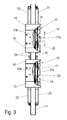
- the Figures 3 and 4 show an embodiment in which on a guide rail 11, two guide carriages 10 are placed, which are mirror images of each other.
- the execution according to the Figures 3 and 4 corresponds essentially to the embodiment according to the FIG. 2
- on the piston rods of the linear drives 21, 22 are still placed on the brake wedges 17 acting plungers.
- adjusting screws 30, 31 are provided on the regions containing the force accumulators 24 in order to adjust or set the displacement path of each brake wedge 17.
- the linear drives 21, 22 on the opposite sides, but are arranged in mirror image, as the figure shows.
- the guide carriage 10 are identical to the guide carriage according to the FIG. 3 , however, these guide slides 10 are again arranged in mirror image to one another, but the linear drives 21, 22 are located on the mutually facing sides, so that the adjusting screws 30, 31 are provided on the sides facing away from each other.
- the linear axis is equipped with a guide carriage 10, which is equipped with only one brake wedge 17, which lies on one side of the guide rail 11.
- a support member 32 On the opposite side of the guide rail 11 is associated with a support member 32, which may be a floating caliper.
- a plurality of guide carriages 10 could also be placed on the guide rail 11, which are arranged in series, and in which two successive guide carriages 10 are again set in mirror image with respect to one another.
- the guide carriage 10 moves away from the guide rail 11 when the brake wedge 17 is moved to the operative position, and it moves in the opposite direction, ie towards the guide rail 11 when the brake wedge 17 is moved to the release position, such as indicated by the double arrow A.
- each guide rail 11, 12 is stationary, and the guide carriage 10 is moved in the longitudinal direction
- the guide rail 11 could be moved in the inversion and the guide carriage 10 and the guide carriage 10 are arranged stationary.
- each guide rail 11, 12 at least one brake wedge 17 is assigned, but that preferably each side of each guide rail 11, 12 a respective brake wedge 17 is arranged.
- each brake wedge 17 is positioned by means of the linear drive in the form of a pneumatic cylinder 21, 22 so that the brake wedges become ineffective.
- the compression springs 24 are relaxed and the brake wedges 17 contact the respective guide rail 11, 12.
Landscapes
- Engineering & Computer Science (AREA)
- General Engineering & Computer Science (AREA)
- Mechanical Engineering (AREA)
- Braking Arrangements (AREA)
- Bearings For Parts Moving Linearly (AREA)
Abstract
Description
Die Erfindung betrifft eine Linearachse mit mindestens einer vertikalen Führungsschiene und mit einem längs der Führungsschiene bzw. der Führungsschienen mittels eines Antriebs verfahrbaren, ein Gehäuse aufweisenden Führungsschlitten.The invention relates to a linear axis with at least one vertical guide rail and with a along the guide rail or the guide rails by means of a drive movable, a housing having guide carriage.
Die in Rede stehenden Linearachsen werden u.a. in Automatisierungsanlagen eingebaut. Üblicherweise sind derartige Linearachsen mit Führungsschlitten ausgerüstet, die längs eines räumlichen Koordinatensystems verfahren werden. Problematisch ist bei solchen Linearachsen das Verfahren in Richtung der sogenannten Z-Achse, die durch die vertikale Führungsschiene bzw. durch die vertikalen Führungsschienen bestimmt ist. Sofern die Linearachsen mit mehr als einer Führungsschiene ausgerüstet sind, verlaufen diese achsparallel zueinander.The linear axes in question are u.a. installed in automation systems. Usually, such linear axes are equipped with guide carriages which are moved along a spatial coordinate system. The problem with such linear axes, the method in the direction of the so-called Z-axis, which is determined by the vertical guide rail or by the vertical guide rails. If the linear axes are equipped with more than one guide rail, they run parallel to each other.
Als Antriebe für die Führungsschlitten können die in der Antriebstechnik bewährten Bauelemente eingesetzt werden. Unabhängig von der Art des Antriebes müssen diese Antriebe so ausgelegt sein, dass der Führungsschlitten in jeder Stellung unabhängig und redundant von der Motorbremse gehalten wird.As drives for the guide carriage, the proven in drive technology components can be used. Regardless of the type of drive these drives must be designed so that the guide carriage is held in each position independently and redundantly by the engine brake.
Bei Wartungsarbeiten ist es üblich, die Führungsschlitten zusätzlich zu sichern, beispielsweise durch eine separate Fixierung über eine Hilfsvorrichtung bzw. störende Aufbauten außerhalb der Linearachse, wie z.B. eine Stütze. Diese Maßnahmen sind jedoch von der Handhabung her recht umständlich und erfüllen in ungenügender Weise die Sicherheitsvorschriften. Im Falle einer Betriebsunterbrechung, beispielsweise durch Energieausfall, fährt der Führungsschlitten ungebremst entlang der die Z-Achse bildenden Führungsschiene bzw. der Führungsschienen. Die Unfallgefahr ist in einem solchen Falle entsprechend hoch.During maintenance work, it is customary to additionally secure the guide carriages, for example by means of a separate fixing via an auxiliary device or disruptive structures outside the linear axis, such as, for example, a prop. However, these measures are quite cumbersome to handle and inadequate fulfill the safety requirements. In the event of an interruption in operation, for example due to power failure, the guide carriage runs unrestrained along the Z-axis forming guide rail or the guide rails. The risk of accidents is correspondingly high in such a case.
Der Erfindung liegt die Aufgabe zugrunde, eine Linearachse der eingangs näher beschriebenen Art so zu gestalten, dass im Normalbetrieb der die Last tragende Führungsschlitten frei beweglich ist, dass jedoch im Falle einer Betriebsunterbrechung, beispielsweise bei Wartungs-, Reparaturarbeiten, einer Störung oder dergleichen, beispielsweise durch einen Energieausfall, der Führungsschlitten entweder gebremst noch weiter verfahren werden kann, dass jedoch auch im Bedarfsfalle der Führungsschlitten nach einem relativ kurzen Bremsweg in dieser Stellung verbleibt.The invention has for its object to make a linear axis of the type described in more detail so that during normal operation of the load-carrying guide carriage is free to move, but that in the event of an interruption in operation, for example, during maintenance, repair work, a fault or the like, For example, by a power failure, the guide carriage either braked can be moved further, but that remains in case of need, the guide carriage after a relatively short braking distance in this position.
Die gestellte Aufgabe wird dadurch gelöst, dass jeder Führungsschiene mindestens ein in der Längsrichtung der Führungsschiene verfahrbarer Bremskeil zugeordnet ist, dass im Normalbetrieb jeder Bremskeil mittels eines Linearantriebes in eine Außerbetriebsstellung verfahren ist, und dass im Falle einer Betriebsunterbrechung der Linearantrieb wirkungslos und der Bremskeil mittels eines mechanischen Kraftspeichers in die Wirkstellung verfahrbar ist.The stated object is achieved in that each guide rail is associated with at least one movable in the longitudinal direction of the guide rail brake wedge, that in normal operation each brake wedge is moved by means of a linear drive in an inoperative position, and that in the event of an interruption of operation of the linear drive ineffective and the brake wedge means of a mechanical energy storage can be moved in the operative position.
Unter dem Normalbetrieb wird verstanden, dass der Führungsschlitten längs der vertikalen Führungsschiene oder längs der vertikalen Führungsschienen gesteuert verfahrbar ist, während im Falle einer Betriebsunterbrechung der Führungsschlitten entweder gebremst verfahren oder in seiner Stellung verbleibt. Der Bremskeil könnte dann auch als Haltekeil bezeichnet werden, so dass eine Sicherung gegen unbeabsichtigtes Absenken gewährleistet ist, und zwar unabhängig und redundant von der Motorbremse des Antriebes für den Führungsschlitten.Under normal operation, it is understood that the guide carriage can be moved in a controlled manner along the vertical guide rail or along the vertical guide rails, while in the event of an interruption in operation, the guide carriage either traverses decelerated or remains in its position. The brake wedge could then also be referred to as a retaining wedge, so that a safeguard against unintentional lowering is ensured, namely independently and redundantly of the engine brake of the drive for the guide carriage.
Der Vorteil des Linearantriebes ist darin zu sehen, dass dieser im Normalbetrieb aktiviert ist und den Bremskeil in der wirkungslosen Position hält, während bei einer Betriebsunterbrechung oder einem Defekt der mechanische Kraftspeicher den Bremskeil in die Wirkstellung bzw. Brems- oder Haltestellung verfährt. Der mechanische Kraftspeicher ist demzufolge unabhängig von der Funktion des Antriebes für den Führungsschlitten oder von der Stromversorgung. Bei notwendigen Wartungsarbeiten an der Linearachse wird beispielsweise über einen Hauptschalter die die Linearachse aufweisende Anlage stromlos geschaltet. In diesem Falle wird auch der Linearantrieb wirkungslos, so dass der mechanische Kraftspeicher sich entspannen kann und den zugeordneten Haltekeil in die Wirkstellung verfährt.The advantage of the linear drive is the fact that it is activated in normal operation and holds the brake wedge in the ineffective position, while in an operation interruption or a defect in the mechanical energy storage the wedge moves into the operative position or braking or holding position. The mechanical energy storage is therefore independent of the function of the drive for the guide carriage or from the power supply. When necessary maintenance work on the linear axis, for example, via a main switch, the plant having the linear axis is de-energized. In this case, the linear drive is ineffective, so that the mechanical energy storage can relax and moves the associated retaining wedge in the operative position.
Als Linearantriebe kommen die in der Antriebstechnik bekannten Ausführungen zum Einsatz. Bevorzugt kommt jedoch eine Kolbenzylindereinheit, vorzugsweise in Form eines Pneumatikzylinders in Betracht. Es können jedoch auch Elektrozylinder sowie hydraulische Kolbenzylindereinheiten und dergleichen eingesetzt werden.As linear drives known in the drive technology designs are used. Preferably, however, comes a piston-cylinder unit, preferably in the form of a pneumatic cylinder into consideration. However, it can also be electric cylinders and hydraulic piston-cylinder units and the like are used.
Für die Funktion der Linearachse ist es vorteilhaft, wenn die im Normalbetrieb von jedem Linearantrieb auf den Bremskeil einwirkende Kraft größer ist als die von dem Kraftspeicher aufzubringende Kraft. Im Normalbetrieb ist die von jedem Linearantrieb auf den Bremskeil einwirkende Kraft als Dauerkraft anzusehen.For the function of the linear axis, it is advantageous if the force acting on the brake wedge by each linear drive during normal operation is greater than the force to be applied by the force store. In normal operation, the force acting on the brake wedge by each linear drive is to be regarded as a continuous force.
In bevorzugter Ausführung ist die Linearachse mit einer Führungsschiene oder mit zwei parallel und im Abstand zueinander stehenden Führungsschienen versehen. Um ein Kräftegleichgewicht zu erzielen, wenn mittels des mechanischen Kraftspeichers bei einer Betriebsunterbrechung der Haltekeil in die Wirkstellung verfahren wird, ist vorgesehen, dass zumindest einer Führungsschiene zwei einander gegenüberliegende Bremskeile zugeordnet sind.In a preferred embodiment, the linear axis is provided with a guide rail or with two parallel and spaced guide rails. In order to achieve an equilibrium of forces when the retaining wedge is moved into the active position by means of the mechanical force accumulator in the event of an interruption in operation, it is provided that at least one guide rail is assigned two opposing brake wedges.
Zur Minimierung der Teilevielfalt ist vorgesehen, dass an dem Gehäuse des Führungsschlittens beidseitig jeder Führungsschiene jeweils eine Schrägfläche vorgesehen ist, die mit der Keilfläche des Bremskeiles in Wirkverbindung steht. Beim Verfahren des Bremskeiles mittels des Kraftspeichers kommt dann die der Schrägfläche gegenüberliegende Fläche mit der Führungsschiene über die gesamte Länge in Kontakt. In weiterer Ausgestaltung dieser Ausführung ist dann noch vorgesehen, dass zwischen den Schrägflächen des Gehäuses des Führungsschlittens und den Schrägflächen der Bremskeile jeweils eine aus mehreren beabstandeten Rollen oder Nadeln gebildete Rollenführung vorgesehen ist. Dadurch wird sinngemäß ein Linearwälzlager geschaffen, so dass sichergestellt ist, dass jeder Bremskeil auch durch den sich entspannenden mechanischen Kraftspeicher mit minimierten Reibkräften verfahrbar ist, so dass der Linearantrieb mit minimalen Axialkräften betrieben werden kann. Des Weiteren wird durch diese konstruktive Ausführung eine relativ große Brems- und Haltekraft erzeugt, bedingt durch die relativ große Differenz zwischen der Rollreibung und der Gleit- bzw. Haftreibung an den Kontaktflächen der Führungsschiene zum Bremsbelag. Ein weiterer Vorteil ist noch darin zu sehen, dass die Wirkungen der Bremskeile auch dann voll erhalten bleiben, wenn die einander kontaktierenden Flächen mit einem Film aus einem Schmierstoff versehen sind.To minimize the variety of parts is provided that on each side of each guide rail an inclined surface is provided on the housing of the guide carriage, which is in operative connection with the wedge surface of the brake wedge. When moving the brake wedge by means of the energy storage then the inclined surface opposite surface comes with the guide rail over the entire length in contact. In a further embodiment of this embodiment is then still provided that is provided between the inclined surfaces of the housing of the guide carriage and the inclined surfaces of the brake wedges each formed of a plurality of spaced rollers or needles roller guide. As a result, a linear roller bearing is created, so that it is ensured that each brake wedge can also be moved by the relaxing mechanical energy accumulator with minimized frictional forces, so that the linear drive can be operated with minimal axial forces. Furthermore, a relatively large braking and holding force is generated by this structural design, due to the relatively large difference between the rolling friction and the sliding or static friction at the contact surfaces of the guide rail to the brake pad. Another advantage is to be seen in the fact that the effects of the brake wedges remain fully intact even when the surfaces which are in contact with one another are provided with a film of a lubricant.
In weiterer Ausgestaltung ist noch vorgesehen, dass jeder Bremskeil aus einem Sockel und aus einem Bremsbelag besteht. Der Sockel liegt bei dieser Ausführung der zugeordneten Schrägfläche des Gehäuses des Führungsschlittens zugewandt und der Bremsbelag liegt an der der Führungsschiene zugewandten Seite. Der Bremsbelag ist aus einem üblichen Material mit einem entsprechenden Reibwert gefertigt. Damit sich der Bremsbelag auch bei relativ großen Kräften nicht vom Sockel löst, ist vorgesehen, dass er in einer Aussparung des Sockels eingesetzt ist.In a further embodiment, it is also provided that each brake wedge consists of a base and a brake pad. The base is facing in this embodiment, the associated inclined surface of the housing of the guide carriage and the brake pad is located on the side facing the guide rail. The brake pad is made of a conventional material with a corresponding coefficient of friction. Thus, the brake pad does not detach from the base even with relatively large forces, it is provided that it is inserted in a recess of the base.
Da die auf die Führungsschlitten einwirkenden Kräfte je nach Verwendungszweck unterschiedlich sind bzw. sich je nach dem Einsatz ändern, ist vorgesehen, dass die von dem Kraftspeicher auf den Bremskeil einwirkende Schubkraft einstellbar ist. Diese Einstellung beeinflusst außerdem die Reibkräfte zwischen der Führungsschiene und dem Bremsbelag. Der Kraftspeicher ist in bevorzugter Ausführung eine Druckfeder oder eine Gasfeder. Dies erfolgt beispielsweise durch eine stärkere Vorspannung des Kraftspeichers. Sofern der Kraftspeicher in bevorzugter Ausführung eine Druckfeder ist, wird durch Stellschrauben die Vorspannung verändert. Bei dieser Ausführung sind dann noch zwischen der zugeordneten Fläche des Gehäuses und den Schraubenköpfen Dämpfungsringe vorgesehen.Since the forces acting on the guide slides are different depending on the intended use or change depending on the use, it is provided that the thrust force acting on the brake wedge from the force accumulator is adjustable. This adjustment also affects the frictional forces between the guide rail and the brake pad. The energy accumulator is in a preferred embodiment, a compression spring or a gas spring. This is done for example by a stronger bias of the energy storage. If the power storage in a preferred embodiment is a compression spring, the bias is changed by adjusting screws. In this embodiment, damping rings are then still provided between the associated surface of the housing and the screw heads.
Zur Erleichterung der Montage der Bremskeile ist vorgesehen, dass in das Gehäuse der Linearachse Führungsstifte zum Fixieren jedes Bremskeiles eingesetzt sind. Dabei sind zweckmäßigerweise für jeden Bremskeil zwei im Abstand zueinander stehende Führungsstifte vorgesehen. Diese Führungsstifte stehen senkrecht zu den Gleitflächen für die Bremskeile.To facilitate the assembly of the brake wedges is provided that in the housing of the linear axis guide pins are used for fixing each brake wedge. In this case, two spaced apart guide pins are expediently provided for each brake wedge. These guide pins are perpendicular to the sliding surfaces for the brake wedges.
Die Keilwinkel des Bremskeiles liegt unter 5 Grad.The wedge angle of the brake wedge is less than 5 degrees.
In weiterer Ausgestaltung der vorliegenden Erfindung ist vorgesehen, dass auf jede Führungsschiene mindestens zwei Führungsschlitten aufgesetzt sind. Dadurch besteht dann die Möglichkeit, dass die von den Bremskeilen aufgebrachten Bremskräfte entsprechend der Anzahl der Führungsschlitten erhöht wird. Sofern jeder Führungsschlitten mit zwei Bremskeilen ausgestattet ist, ist die Anzahl der Bremskeile doppelt so hoch wie die Anzahl der Führungsschlitten. Man kann jedoch davon ausgehen, dass sich die Bremskräfte bei zwei Führungsschlitten nicht verdoppeln bzw. bei drei Führungsschlitten verdreifachen.In a further embodiment of the present invention, it is provided that at least two guide carriages are placed on each guide rail. This then makes it possible for the braking forces applied by the brake wedges to be increased in accordance with the number of guide carriages. If each guide carriage is equipped with two brake wedges, the number of brake wedges is twice as high as the number of guide carriages. One can, however, of it assume that the braking forces do not double with two guide carriages or triple with three guide carriages.
Es ist besonders vorteilhaft, wenn die Anzahl der Führungsschlitten eine gerade Zahl ist. Besonders vorteilhaft ist, dass die in Reihe angeordneten Führungsschlitten wechselweise spiegelbildlich zueinander angeordnet sind. Sofern zwei Führungsschlitten auf die Führungsschiene aufgesetzt sind, ergibt sich der große Vorteil, dass die Bremswirkung der Führungsschlitten in beiden Richtungen der Führungsschlitten wirksam werden kann bzw., dass die Bremswirkung sowohl beim Absenken als auch beim Anheben der Führungsschlitten erzeugt werden kann.It is particularly advantageous if the number of guide carriages is an even number. It is particularly advantageous that the guide carriages arranged in series are arranged alternately mirror-inverted. If two guide slides are mounted on the guide rail, there is the great advantage that the braking effect of the guide carriage can be effective in both directions of the guide carriage or that the braking effect can be generated both when lowering and when lifting the guide carriage.
Besonders vorteilhaft ist, wenn beispielsweise zwei spiegelbildlich zueinander auf die Führungsschiene aufgesetzten Führungsschlitten im Falle einer Betriebsunterbrechung die Bremskeile eines Führungsschlittens in der Außerbetriebsstellung und die Bremskeile des anderen Führungsschlittens in die Wirkstellung gefahren sind.It is particularly advantageous if, for example, two mirror images of each other placed on the guide rail guide carriage in the event of an operational interruption, the brake wedges of a guide carriage in the inoperative position and the brake wedges of the other guide carriage are moved into the active position.
In besonders vorteilhafter Weise ist das Gehäuse jedes Führungsschlittens im Querschnitt U-förmig gestaltet. An einer Seite ist dann das Gehäuse mit einer schlitzartigen Öffnung versehen, so dass das Gehäuse von dieser Seite aus eingesehen werden kann.In a particularly advantageous manner, the housing of each guide carriage is designed in cross-section U-shaped. On one side, the housing is then provided with a slot-like opening, so that the housing can be viewed from this side.
Ferner ist noch vorgesehen, dass der Verschiebeweg jedes Bremskeiles durch mindestens eine Einstellschraube justierbar ist. Diese Einstellschrauben liegen den Kraftspeichern gegenüber, so dass durch die Kraft der Kraftspeicher die Brems- bzw. Haltekraft entsprechend den jeweiligen Gegebenheiten einstellbar ist.Furthermore, it is provided that the displacement of each brake wedge is adjustable by at least one adjusting screw. These adjusting screws are opposite the force accumulators, so that the braking or holding force can be adjusted according to the particular circumstances by the force of the energy accumulator.
Gemäß einer weiteren Ausführungsform ist vorgesehen, dass jeder Führungsschlitten mit einem der Führungsschiene zugeordneten Bremskeil ausgestattet ist, und dass der Führungsschlitten quer zur Führungsschiene bewegbar ist. Je nach den Einsatzmöglichkeiten kann diese vereinfachte Ausführung ausreichend sein, um die Last zu halten bzw. gebremst zu bewegen. Dabei ist es dann vorteilhaft, wenn an der dem Bremskeil abgewandten Seite ein bewegliches Stützelement angebracht ist, welches zur Stabilisierung der Führungsschiene beiträgt, so dass eine Biegung der Führungsschiene ausgeschlossen werden kann, wenn der Bremskeil in die Wirkstellung gefahren wird. Außerdem kann ein baugleiches Gehäuse verwendet werden, bei dem der zweite Bremskeil durch das Stützelement ersetzt ist.According to a further embodiment, it is provided that each guide carriage is equipped with a brake wedge associated with the guide rail, and that the guide carriage is movable transversely to the guide rail. Depending on the applications, this simplified version may be sufficient to hold the load or to slow it down. It is advantageous if on the side facing away from the brake wedge, a movable support member is mounted, which contributes to the stabilization of the guide rail, so that a bending of the guide rail can be excluded when the brake wedge in the Acting position is driven. In addition, a housing of identical design can be used, in which the second brake wedge is replaced by the support element.
Bei den zuvor beschriebenen Ausführungen wird jeder Führungsschlitten in Richtung der Längsachse der Führungsschiene verfahren. In Umkehrung dieser Ausführung ist es jedoch auch denkbar, dass bei einer Linearachse der zuvor beschriebenen Art jeder Führungsschlitten fest bzw. ortsfest angeordnet ist, und dass jede Führungsschiene in ihrer Längsrichtung verfahrbar ist.In the embodiments described above, each guide carriage is moved in the direction of the longitudinal axis of the guide rail. In a reversal of this embodiment, however, it is also conceivable that in the case of a linear axis of the type described above each guide carriage is fixedly or stationarily arranged, and that each guide rail can be moved in its longitudinal direction.
Anhand der beiliegenden Zeichnungen wird die Erfindung noch näher erläutert.Reference to the accompanying drawings, the invention will be explained in more detail.
Es zeigen:
- Figur 1
- eine erfindungsgemäße Linearachse in einer Teilansicht, den Füh- rungsschlitten zeigend
- Figur 2
- die Brems- und Halteeinrichtung der erfindungsgemäßen Linearachse als Einzelheit im Halbschnitt
- Figur 3
- eine Linearachse in einer zweiten Ausführung mit zwei auf eine Füh- rungsschiene aufgesetzten Führungsschlitten in Ansicht, teilweise auf- gebrochen
- Figur 4
- eine der
Figur 3 entsprechende Darstellung, bei der jedoch die Füh- rungsschlitten gegenüber der Ausführung nach derFigur 3 um 180° versetzt sind und - Figur 5
- die Linearachse in einer dritten Ausführung mit nur einem Bremskeil, in Ansicht teilweise aufgeschnitten.
- FIG. 1
- a linear axis according to the invention in a partial view, showing the guide carriage
- FIG. 2
- the braking and holding device of the linear axis according to the invention as a detail in half section
- FIG. 3
- a linear axis in a second embodiment with two mounted on a guide rail guide carriage in view, partially broken
- FIG. 4
- one of the
FIG. 3 corresponding representation, but in which the guide carriage compared to the execution of theFIG. 3 are offset by 180 ° and - FIG. 5
- the linear axis in a third version with only one brake wedge, in view partially cut open.
In der vereinfachten Darstellung ist in der
Der in der
Die dieser Brems- und Halteeinrichtung 13 zugeordnete Laufschiene 11 ist gemäß der
Jeder Bremskeil 17 besteht aus einem Sockel 17a und einem Bremsbelag 17b. Wie die
Die Bremskeile 17 sind mit Linearantrieben in Form von Pneumatikzylindern 21, 22 antriebstechnisch gekoppelt. Die Kolben bzw. die Kolbenstangen dieser Pneumatikzylinder 21, 22 sind über Druckstücke 23 mit den Bremskeilen 17 gekoppelt. Die Pneumatikzylinder 21, 22 liegen in Aufwärtsrichtung des Führungsschlittens 10 gesehen vorn. An der gegenüberliegenden Seite wirkt auf jeden Bremskeil 17 ein Kraftspeicher in Form einer Druckfeder 24, der jedoch auch eine Gasfeder sein kann. Jede Druckfeder 24 kann zur Erzeugung einer unterschiedlichen Vorspannkraft mittels jeweils einer Einstellschraube 25, 26 ge- oder entspannt werden. Zwischen der Stirnfläche des Deckels 16 und den Köpfen der Einstellschrauben 25, 26 sind noch Dämpfungsringe 27, 28 vorgesehen, die beim Aktivieren der Druckfeder 24 ein schlagartiges Aufsetzen der Köpfe der Einstellschrauben 25, 26 verhindern.The
Im Normalbetrieb, d.h., wenn die mit der Linearachse ausgerüstete Anlage in Funktion ist, werden die Pneumatikzylinder 21, 22 druckbeaufschlagt. Der Druck ist so eingestellt, dass die Bremskeile 17 in Richtung zu den Druckfedern 24 verfahren werden, da die von den Pneumatikzylindern 21, 22 aufgebrachten Kräfte größer sind als die Kräfte der vorgespannten Druckfedern 24. Die Bremskeile 17 sind in dieser Stellung wirkungslos. Wird jedoch beispielsweise die elektrische Versorgung der Anlage unterbrochen, werden die Pneumatikzylinder 21, 22 schlagartig drucklos. Durch die Entspannung der Druckfedern 24 werden die Bremskeile 17 in Richtung zu den Pneumatikzylindern 21, 22 verschoben.In normal operation, i.e. when the equipment equipped with the linear axis is in operation, the
Die
Die
Bei der Ausführung gemäß der
Bei der Ausführung gemäß der
Entgegen den beschriebenen Ausführungen, bei denen jede Führungsschiene 11, 12 ortsfest ist, und die Führungsschlitten 10 in deren Längsrichtung verfahren wird, könnte in der Umkehrung auch die Führungsschiene 11 verfahren werden und der Führungsschlitten 10 bzw. die Führungsschlitten 10 sind ortsfest angeordnet.Contrary to the described embodiments, in which each
Die Erfindung ist nicht auf das dargestellte Ausführungsbeispiel beschränkt. Wesentlich ist, dass jeder Führungsschiene 11, 12 mindestens ein Bremskeil 17 zugeordnet ist, dass jedoch vorzugsweise beidseitig jeder Führungsschiene 11, 12 jeweils ein Bremskeil 17 angeordnet ist. Im Normalbetrieb einer mit der Linearachse ausgerüsteten Anlage wird jeder Bremskeil 17 mittels des Linearantriebes in Form eines Pneumatikzylinders 21, 22 so positioniert, dass die Bremskeile unwirksam werden. Kommt es jedoch zu einer Betriebsunterbrechung, werden die Druckfedern 24 entspannt und die Bremskeile 17 kontaktieren die jeweilige Führungsschiene 11, 12.The invention is not limited to the illustrated embodiment. It is essential that each
Claims (15)
Applications Claiming Priority (2)
| Application Number | Priority Date | Filing Date | Title |
|---|---|---|---|
| DE202009002076U DE202009002076U1 (en) | 2009-04-17 | 2009-04-17 | linear axis |
| DE202009012485U DE202009012485U1 (en) | 2009-04-17 | 2009-09-14 | linear axis |
Publications (3)
| Publication Number | Publication Date |
|---|---|
| EP2241771A2 true EP2241771A2 (en) | 2010-10-20 |
| EP2241771A3 EP2241771A3 (en) | 2011-08-31 |
| EP2241771B1 EP2241771B1 (en) | 2012-12-19 |
Family
ID=40794845
Family Applications (1)
| Application Number | Title | Priority Date | Filing Date |
|---|---|---|---|
| EP10159624A Not-in-force EP2241771B1 (en) | 2009-04-17 | 2010-04-12 | Linear axis |
Country Status (4)
| Country | Link |
|---|---|
| US (1) | US20100263472A1 (en) |
| EP (1) | EP2241771B1 (en) |
| DE (2) | DE202009002076U1 (en) |
| ES (1) | ES2401574T3 (en) |
Families Citing this family (5)
| Publication number | Priority date | Publication date | Assignee | Title |
|---|---|---|---|---|
| DE102009036978B4 (en) * | 2009-08-12 | 2014-04-03 | Hema Maschinen- Und Apparateschutz Gmbh | Brake element for vertical linear guides |
| DE202010005769U1 (en) | 2010-04-16 | 2010-07-29 | ACE Stoßdämpfer GmbH | linear axis |
| DE102010018183A1 (en) * | 2010-04-22 | 2011-10-27 | Günther Zimmer | Device with various gears and functional sequence of the device |
| DE202011050644U1 (en) | 2011-07-06 | 2011-08-25 | Rk Rose + Krieger Gmbh Verbindungs- Und Positioniersysteme | linear axis |
| CN110566580B (en) * | 2019-09-16 | 2024-05-14 | 吉林大学 | Guide rail type actuator travel protection device |
Family Cites Families (16)
| Publication number | Priority date | Publication date | Assignee | Title |
|---|---|---|---|---|
| GB1301471A (en) * | 1968-10-29 | 1972-12-29 | ||
| GB1226439A (en) * | 1968-12-09 | 1971-03-31 | ||
| GB1488374A (en) * | 1974-06-21 | 1977-10-12 | Coal Ind | Brakes for vehicles |
| DE2744986A1 (en) * | 1977-10-06 | 1979-04-12 | Wyhlen Ag Eisenbau | CATCH BRAKE |
| FI74686C (en) * | 1986-05-06 | 1988-03-10 | Kone Oy | Prisoner, for example for lift basket or counterweight. |
| FI85129C (en) * | 1989-12-14 | 1992-03-10 | Kone Oy | catching device |
| DE4116795C2 (en) * | 1991-05-23 | 1998-09-03 | Schaeffler Waelzlager Ohg | Clamping device for a table or the like movable along one or more guide rails |
| JP3090809B2 (en) * | 1993-03-05 | 2000-09-25 | 株式会社東芝 | Self-propelled elevator |
| DE19715014A1 (en) * | 1997-04-11 | 1998-10-15 | Schaeffler Waelzlager Ohg | Linear guide |
| DE19805449A1 (en) * | 1998-02-11 | 1999-08-12 | Schaeffler Waelzlager Ohg | Braking device for a linear guide |
| KR100279363B1 (en) * | 1998-12-12 | 2001-01-15 | 장병우 | Emergency stop of elevator |
| JP2001192184A (en) * | 2000-01-11 | 2001-07-17 | Toshiba Corp | Elevator emergency stop device |
| TW513374B (en) * | 2000-12-08 | 2002-12-11 | Inventio Ag | Safety brake with retardation-dependent braking force |
| ATE491662T1 (en) * | 2003-10-07 | 2011-01-15 | Otis Elevator Co | REMOTE-RESETABLE CABLE-LESS EMERGENCY STOP DEVICE FOR AN ELEVATOR |
| US7124861B2 (en) * | 2004-02-20 | 2006-10-24 | Nexen Group, Inc. | Motion control apparatus |
| DE102005016719B4 (en) * | 2005-04-11 | 2009-04-09 | Zimmer, Günther | Brake and clamping device with partially wedge-shaped friction pads |
-
2009
- 2009-04-17 DE DE202009002076U patent/DE202009002076U1/en not_active Expired - Lifetime
- 2009-09-14 DE DE202009012485U patent/DE202009012485U1/en not_active Expired - Lifetime
-
2010
- 2010-04-12 EP EP10159624A patent/EP2241771B1/en not_active Not-in-force
- 2010-04-12 ES ES10159624T patent/ES2401574T3/en active Active
- 2010-04-14 US US12/760,100 patent/US20100263472A1/en not_active Abandoned
Non-Patent Citations (1)
| Title |
|---|
| None |
Also Published As
| Publication number | Publication date |
|---|---|
| DE202009012485U1 (en) | 2010-02-04 |
| ES2401574T3 (en) | 2013-04-22 |
| DE202009002076U1 (en) | 2009-06-25 |
| US20100263472A1 (en) | 2010-10-21 |
| EP2241771B1 (en) | 2012-12-19 |
| EP2241771A3 (en) | 2011-08-31 |
Similar Documents
| Publication | Publication Date | Title |
|---|---|---|
| DE19880452B4 (en) | linear guide | |
| DE102004004348B4 (en) | Linear guide device | |
| DE102007013421A1 (en) | Braking device with a wedge mechanism | |
| EP2241771B1 (en) | Linear axis | |
| EP1483515A1 (en) | Brake, especially for wind farms | |
| DE102020210860A1 (en) | Multi-part spring for a ball screw | |
| DE102011084177A1 (en) | Gripping or clamping device | |
| EP3468908B1 (en) | Lifting mechanism with safety brake | |
| EP2813722A2 (en) | Rail driven carriage braking and/or clamping device with cage integrated in the piston rod | |
| WO2007122077A1 (en) | Floating-caliper brake | |
| DE10225353A1 (en) | Electromagnetically liftable brake has a coil and armature to lift against a spring whose force depends on a tapering in the brake body | |
| DE102013226826A1 (en) | Linear motor assembly and machine tool with a linear motor assembly | |
| DE19957939C2 (en) | Electromagnetic brake device | |
| DE102006062295A1 (en) | Clamping device for attachment to carriage, has clamping element to provide braking force acting on rail and defining bisecting line having direction corresponding with direction of drive force acting on clamping element | |
| EP4038002B1 (en) | Braking device | |
| DE102008032522A1 (en) | Rolling device with adjusting device | |
| DE102010021859B4 (en) | Braking and / or locking device of a slide movable on a rail | |
| EP1782914B1 (en) | Telescopic cover for a machine-tool | |
| DE29807438U1 (en) | Magnetically preloaded linear guide | |
| EP4104966B1 (en) | Clamping device | |
| DE9401049U1 (en) | Clamping element for a linear guide | |
| DE102011017757B4 (en) | Concept for sealing a linear guide | |
| DE102005055673A1 (en) | Disk brake for motor vehicle, has brake caliper such as pin-slide caliper, formed as multipart and including two shanks that are misaligned against each other in normal direction running perpendicular to friction surfaces | |
| DE102014113486B4 (en) | Rope clamp | |
| EP1249410A2 (en) | Air cushion apparatus with a platform and a support |
Legal Events
| Date | Code | Title | Description |
|---|---|---|---|
| PUAI | Public reference made under article 153(3) epc to a published international application that has entered the european phase |
Free format text: ORIGINAL CODE: 0009012 |
|
| AK | Designated contracting states |
Kind code of ref document: A2 Designated state(s): AT BE BG CH CY CZ DE DK EE ES FI FR GB GR HR HU IE IS IT LI LT LU LV MC MK MT NL NO PL PT RO SE SI SK SM TR |
|
| AX | Request for extension of the european patent |
Extension state: AL BA ME RS |
|
| PUAL | Search report despatched |
Free format text: ORIGINAL CODE: 0009013 |
|
| AK | Designated contracting states |
Kind code of ref document: A3 Designated state(s): AT BE BG CH CY CZ DE DK EE ES FI FR GB GR HR HU IE IS IT LI LT LU LV MC MK MT NL NO PL PT RO SE SI SK SM TR |
|
| AX | Request for extension of the european patent |
Extension state: AL BA ME RS |
|
| RIC1 | Information provided on ipc code assigned before grant |
Ipc: F16C 29/10 20060101AFI20110728BHEP |
|
| 17P | Request for examination filed |
Effective date: 20120228 |
|
| 17Q | First examination report despatched |
Effective date: 20120504 |
|
| GRAP | Despatch of communication of intention to grant a patent |
Free format text: ORIGINAL CODE: EPIDOSNIGR1 |
|
| RIC1 | Information provided on ipc code assigned before grant |
Ipc: F16C 29/06 20060101ALI20120626BHEP Ipc: F16D 65/14 20060101ALI20120626BHEP Ipc: F16D 63/00 20060101ALI20120626BHEP Ipc: F16C 29/10 20060101AFI20120626BHEP |
|
| GRAS | Grant fee paid |
Free format text: ORIGINAL CODE: EPIDOSNIGR3 |
|
| GRAA | (expected) grant |
Free format text: ORIGINAL CODE: 0009210 |
|
| AK | Designated contracting states |
Kind code of ref document: B1 Designated state(s): AT BE BG CH CY CZ DE DK EE ES FI FR GB GR HR HU IE IS IT LI LT LU LV MC MK MT NL NO PL PT RO SE SI SK SM TR |
|
| REG | Reference to a national code |
Ref country code: GB Ref legal event code: FG4D Free format text: NOT ENGLISH |
|
| REG | Reference to a national code |
Ref country code: CH Ref legal event code: EP |
|
| REG | Reference to a national code |
Ref country code: AT Ref legal event code: REF Ref document number: 589582 Country of ref document: AT Kind code of ref document: T Effective date: 20130115 |
|
| REG | Reference to a national code |
Ref country code: DE Ref legal event code: R096 Ref document number: 502010001890 Country of ref document: DE Effective date: 20130207 |
|
| REG | Reference to a national code |
Ref country code: ES Ref legal event code: FG2A Ref document number: 2401574 Country of ref document: ES Kind code of ref document: T3 Effective date: 20130422 |
|
| PG25 | Lapsed in a contracting state [announced via postgrant information from national office to epo] |
Ref country code: SE Free format text: LAPSE BECAUSE OF FAILURE TO SUBMIT A TRANSLATION OF THE DESCRIPTION OR TO PAY THE FEE WITHIN THE PRESCRIBED TIME-LIMIT Effective date: 20121219 Ref country code: NO Free format text: LAPSE BECAUSE OF FAILURE TO SUBMIT A TRANSLATION OF THE DESCRIPTION OR TO PAY THE FEE WITHIN THE PRESCRIBED TIME-LIMIT Effective date: 20130319 Ref country code: HR Free format text: LAPSE BECAUSE OF FAILURE TO SUBMIT A TRANSLATION OF THE DESCRIPTION OR TO PAY THE FEE WITHIN THE PRESCRIBED TIME-LIMIT Effective date: 20121219 Ref country code: FI Free format text: LAPSE BECAUSE OF FAILURE TO SUBMIT A TRANSLATION OF THE DESCRIPTION OR TO PAY THE FEE WITHIN THE PRESCRIBED TIME-LIMIT Effective date: 20121219 Ref country code: LT Free format text: LAPSE BECAUSE OF FAILURE TO SUBMIT A TRANSLATION OF THE DESCRIPTION OR TO PAY THE FEE WITHIN THE PRESCRIBED TIME-LIMIT Effective date: 20121219 |
|
| REG | Reference to a national code |
Ref country code: NL Ref legal event code: VDEP Effective date: 20121219 |
|
| REG | Reference to a national code |
Ref country code: LT Ref legal event code: MG4D |
|
| PG25 | Lapsed in a contracting state [announced via postgrant information from national office to epo] |
Ref country code: GR Free format text: LAPSE BECAUSE OF FAILURE TO SUBMIT A TRANSLATION OF THE DESCRIPTION OR TO PAY THE FEE WITHIN THE PRESCRIBED TIME-LIMIT Effective date: 20130320 Ref country code: LV Free format text: LAPSE BECAUSE OF FAILURE TO SUBMIT A TRANSLATION OF THE DESCRIPTION OR TO PAY THE FEE WITHIN THE PRESCRIBED TIME-LIMIT Effective date: 20121219 Ref country code: SI Free format text: LAPSE BECAUSE OF FAILURE TO SUBMIT A TRANSLATION OF THE DESCRIPTION OR TO PAY THE FEE WITHIN THE PRESCRIBED TIME-LIMIT Effective date: 20121219 |
|
| PG25 | Lapsed in a contracting state [announced via postgrant information from national office to epo] |
Ref country code: CZ Free format text: LAPSE BECAUSE OF FAILURE TO SUBMIT A TRANSLATION OF THE DESCRIPTION OR TO PAY THE FEE WITHIN THE PRESCRIBED TIME-LIMIT Effective date: 20121219 Ref country code: BG Free format text: LAPSE BECAUSE OF FAILURE TO SUBMIT A TRANSLATION OF THE DESCRIPTION OR TO PAY THE FEE WITHIN THE PRESCRIBED TIME-LIMIT Effective date: 20130319 Ref country code: EE Free format text: LAPSE BECAUSE OF FAILURE TO SUBMIT A TRANSLATION OF THE DESCRIPTION OR TO PAY THE FEE WITHIN THE PRESCRIBED TIME-LIMIT Effective date: 20121219 Ref country code: IS Free format text: LAPSE BECAUSE OF FAILURE TO SUBMIT A TRANSLATION OF THE DESCRIPTION OR TO PAY THE FEE WITHIN THE PRESCRIBED TIME-LIMIT Effective date: 20130419 Ref country code: SK Free format text: LAPSE BECAUSE OF FAILURE TO SUBMIT A TRANSLATION OF THE DESCRIPTION OR TO PAY THE FEE WITHIN THE PRESCRIBED TIME-LIMIT Effective date: 20121219 |
|
| PG25 | Lapsed in a contracting state [announced via postgrant information from national office to epo] |
Ref country code: RO Free format text: LAPSE BECAUSE OF FAILURE TO SUBMIT A TRANSLATION OF THE DESCRIPTION OR TO PAY THE FEE WITHIN THE PRESCRIBED TIME-LIMIT Effective date: 20121219 Ref country code: NL Free format text: LAPSE BECAUSE OF FAILURE TO SUBMIT A TRANSLATION OF THE DESCRIPTION OR TO PAY THE FEE WITHIN THE PRESCRIBED TIME-LIMIT Effective date: 20121219 Ref country code: PL Free format text: LAPSE BECAUSE OF FAILURE TO SUBMIT A TRANSLATION OF THE DESCRIPTION OR TO PAY THE FEE WITHIN THE PRESCRIBED TIME-LIMIT Effective date: 20121219 Ref country code: PT Free format text: LAPSE BECAUSE OF FAILURE TO SUBMIT A TRANSLATION OF THE DESCRIPTION OR TO PAY THE FEE WITHIN THE PRESCRIBED TIME-LIMIT Effective date: 20130419 |
|
| PLBE | No opposition filed within time limit |
Free format text: ORIGINAL CODE: 0009261 |
|
| STAA | Information on the status of an ep patent application or granted ep patent |
Free format text: STATUS: NO OPPOSITION FILED WITHIN TIME LIMIT |
|
| BERE | Be: lapsed |
Owner name: RK ROSE + KRIEGER G.M.B.H. VERBINDUNGS- UND POSIT Effective date: 20130430 |
|
| PG25 | Lapsed in a contracting state [announced via postgrant information from national office to epo] |
Ref country code: DK Free format text: LAPSE BECAUSE OF FAILURE TO SUBMIT A TRANSLATION OF THE DESCRIPTION OR TO PAY THE FEE WITHIN THE PRESCRIBED TIME-LIMIT Effective date: 20121219 |
|
| 26N | No opposition filed |
Effective date: 20130920 |
|
| PG25 | Lapsed in a contracting state [announced via postgrant information from national office to epo] |
Ref country code: CY Free format text: LAPSE BECAUSE OF FAILURE TO SUBMIT A TRANSLATION OF THE DESCRIPTION OR TO PAY THE FEE WITHIN THE PRESCRIBED TIME-LIMIT Effective date: 20121219 Ref country code: MC Free format text: LAPSE BECAUSE OF FAILURE TO SUBMIT A TRANSLATION OF THE DESCRIPTION OR TO PAY THE FEE WITHIN THE PRESCRIBED TIME-LIMIT Effective date: 20121219 |
|
| REG | Reference to a national code |
Ref country code: DE Ref legal event code: R097 Ref document number: 502010001890 Country of ref document: DE Effective date: 20130920 |
|
| REG | Reference to a national code |
Ref country code: IE Ref legal event code: MM4A |
|
| PG25 | Lapsed in a contracting state [announced via postgrant information from national office to epo] |
Ref country code: BE Free format text: LAPSE BECAUSE OF NON-PAYMENT OF DUE FEES Effective date: 20130430 |
|
| PG25 | Lapsed in a contracting state [announced via postgrant information from national office to epo] |
Ref country code: IE Free format text: LAPSE BECAUSE OF NON-PAYMENT OF DUE FEES Effective date: 20130412 |
|
| REG | Reference to a national code |
Ref country code: CH Ref legal event code: PL |
|
| PG25 | Lapsed in a contracting state [announced via postgrant information from national office to epo] |
Ref country code: LI Free format text: LAPSE BECAUSE OF NON-PAYMENT OF DUE FEES Effective date: 20140430 Ref country code: CH Free format text: LAPSE BECAUSE OF NON-PAYMENT OF DUE FEES Effective date: 20140430 |
|
| PG25 | Lapsed in a contracting state [announced via postgrant information from national office to epo] |
Ref country code: MT Free format text: LAPSE BECAUSE OF FAILURE TO SUBMIT A TRANSLATION OF THE DESCRIPTION OR TO PAY THE FEE WITHIN THE PRESCRIBED TIME-LIMIT Effective date: 20121219 |
|
| PG25 | Lapsed in a contracting state [announced via postgrant information from national office to epo] |
Ref country code: SM Free format text: LAPSE BECAUSE OF FAILURE TO SUBMIT A TRANSLATION OF THE DESCRIPTION OR TO PAY THE FEE WITHIN THE PRESCRIBED TIME-LIMIT Effective date: 20121219 |
|
| PG25 | Lapsed in a contracting state [announced via postgrant information from national office to epo] |
Ref country code: TR Free format text: LAPSE BECAUSE OF FAILURE TO SUBMIT A TRANSLATION OF THE DESCRIPTION OR TO PAY THE FEE WITHIN THE PRESCRIBED TIME-LIMIT Effective date: 20121219 |
|
| PG25 | Lapsed in a contracting state [announced via postgrant information from national office to epo] |
Ref country code: MK Free format text: LAPSE BECAUSE OF FAILURE TO SUBMIT A TRANSLATION OF THE DESCRIPTION OR TO PAY THE FEE WITHIN THE PRESCRIBED TIME-LIMIT Effective date: 20121219 Ref country code: HU Free format text: LAPSE BECAUSE OF FAILURE TO SUBMIT A TRANSLATION OF THE DESCRIPTION OR TO PAY THE FEE WITHIN THE PRESCRIBED TIME-LIMIT; INVALID AB INITIO Effective date: 20100412 Ref country code: LU Free format text: LAPSE BECAUSE OF NON-PAYMENT OF DUE FEES Effective date: 20130412 |
|
| REG | Reference to a national code |
Ref country code: FR Ref legal event code: PLFP Year of fee payment: 7 |
|
| REG | Reference to a national code |
Ref country code: AT Ref legal event code: MM01 Ref document number: 589582 Country of ref document: AT Kind code of ref document: T Effective date: 20150412 |
|
| PG25 | Lapsed in a contracting state [announced via postgrant information from national office to epo] |
Ref country code: AT Free format text: LAPSE BECAUSE OF NON-PAYMENT OF DUE FEES Effective date: 20150412 |
|
| REG | Reference to a national code |
Ref country code: FR Ref legal event code: PLFP Year of fee payment: 8 |
|
| REG | Reference to a national code |
Ref country code: FR Ref legal event code: PLFP Year of fee payment: 9 |
|
| PGFP | Annual fee paid to national office [announced via postgrant information from national office to epo] |
Ref country code: GB Payment date: 20220303 Year of fee payment: 13 |
|
| PGFP | Annual fee paid to national office [announced via postgrant information from national office to epo] |
Ref country code: IT Payment date: 20220429 Year of fee payment: 13 Ref country code: FR Payment date: 20220407 Year of fee payment: 13 Ref country code: ES Payment date: 20220509 Year of fee payment: 13 Ref country code: DE Payment date: 20220414 Year of fee payment: 13 |
|
| P01 | Opt-out of the competence of the unified patent court (upc) registered |
Effective date: 20230418 |
|
| REG | Reference to a national code |
Ref country code: DE Ref legal event code: R119 Ref document number: 502010001890 Country of ref document: DE |
|
| GBPC | Gb: european patent ceased through non-payment of renewal fee |
Effective date: 20230412 |
|
| PG25 | Lapsed in a contracting state [announced via postgrant information from national office to epo] |
Ref country code: GB Free format text: LAPSE BECAUSE OF NON-PAYMENT OF DUE FEES Effective date: 20230412 |
|
| PG25 | Lapsed in a contracting state [announced via postgrant information from national office to epo] |
Ref country code: GB Free format text: LAPSE BECAUSE OF NON-PAYMENT OF DUE FEES Effective date: 20230412 Ref country code: FR Free format text: LAPSE BECAUSE OF NON-PAYMENT OF DUE FEES Effective date: 20230430 Ref country code: DE Free format text: LAPSE BECAUSE OF NON-PAYMENT OF DUE FEES Effective date: 20231103 |
|
| PG25 | Lapsed in a contracting state [announced via postgrant information from national office to epo] |
Ref country code: IT Free format text: LAPSE BECAUSE OF NON-PAYMENT OF DUE FEES Effective date: 20230412 |
|
| REG | Reference to a national code |
Ref country code: ES Ref legal event code: FD2A Effective date: 20240528 |
|
| PG25 | Lapsed in a contracting state [announced via postgrant information from national office to epo] |
Ref country code: ES Free format text: LAPSE BECAUSE OF NON-PAYMENT OF DUE FEES Effective date: 20230413 |
|
| PG25 | Lapsed in a contracting state [announced via postgrant information from national office to epo] |
Ref country code: ES Free format text: LAPSE BECAUSE OF NON-PAYMENT OF DUE FEES Effective date: 20230413 |