EP2241794B1 - Auslassventil für ein Löschsystem - Google Patents
Auslassventil für ein Löschsystem Download PDFInfo
- Publication number
- EP2241794B1 EP2241794B1 EP10002743A EP10002743A EP2241794B1 EP 2241794 B1 EP2241794 B1 EP 2241794B1 EP 10002743 A EP10002743 A EP 10002743A EP 10002743 A EP10002743 A EP 10002743A EP 2241794 B1 EP2241794 B1 EP 2241794B1
- Authority
- EP
- European Patent Office
- Prior art keywords
- chamber
- pressure
- plug
- gas
- valve
- Prior art date
- Legal status (The legal status is an assumption and is not a legal conclusion. Google has not performed a legal analysis and makes no representation as to the accuracy of the status listed.)
- Active
Links
Images

Classifications
-
- F—MECHANICAL ENGINEERING; LIGHTING; HEATING; WEAPONS; BLASTING
- F16—ENGINEERING ELEMENTS AND UNITS; GENERAL MEASURES FOR PRODUCING AND MAINTAINING EFFECTIVE FUNCTIONING OF MACHINES OR INSTALLATIONS; THERMAL INSULATION IN GENERAL
- F16K—VALVES; TAPS; COCKS; ACTUATING-FLOATS; DEVICES FOR VENTING OR AERATING
- F16K1/00—Lift valves or globe valves, i.e. cut-off apparatus with closure members having at least a component of their opening and closing motion perpendicular to the closing faces
- F16K1/30—Lift valves or globe valves, i.e. cut-off apparatus with closure members having at least a component of their opening and closing motion perpendicular to the closing faces specially adapted for pressure containers
- F16K1/304—Shut-off valves with additional means
- F16K1/306—Shut-off valves with additional means with a valve member, e.g. stem or shaft, passing through the seat
-
- A—HUMAN NECESSITIES
- A62—LIFE-SAVING; FIRE-FIGHTING
- A62C—FIRE-FIGHTING
- A62C35/00—Permanently-installed equipment
- A62C35/58—Pipe-line systems
- A62C35/68—Details, e.g. of pipes or valve systems
-
- F—MECHANICAL ENGINEERING; LIGHTING; HEATING; WEAPONS; BLASTING
- F16—ENGINEERING ELEMENTS AND UNITS; GENERAL MEASURES FOR PRODUCING AND MAINTAINING EFFECTIVE FUNCTIONING OF MACHINES OR INSTALLATIONS; THERMAL INSULATION IN GENERAL
- F16K—VALVES; TAPS; COCKS; ACTUATING-FLOATS; DEVICES FOR VENTING OR AERATING
- F16K31/00—Actuating devices; Operating means; Releasing devices
- F16K31/12—Actuating devices; Operating means; Releasing devices actuated by fluid
- F16K31/122—Actuating devices; Operating means; Releasing devices actuated by fluid the fluid acting on a piston
- F16K31/124—Actuating devices; Operating means; Releasing devices actuated by fluid the fluid acting on a piston servo actuated
Definitions
- the present invention relates to a discharge valve for an extinguishing system of the type intended for their use in centralized extinguishing systems, allowing the adaptation of the high pressure storage to a low or medium pressure distribution.
- the extinguishing agent is generally an inert gas, such as argon, nitrogen or carbon dioxide or an active gas, such as halons.
- the extinguishing agent is generally an inert gas, such as argon, nitrogen or carbon dioxide or an active gas, such as halons.
- the pressure decreases considerably, therefore the gas flow rate also decreases undesirably over time, since the ideal situation would be that the flow rate is constant during a predetermined time period for the venting of the inert gas in the room or enclosure which is to be protected.
- the valve is formed by a body with a high pressure inlet port which can be coupled to a high pressure extinguishing gas source and a low or medium pressure outlet port to distribution means for distributing said gas. Between both ports there is a passage of gas and a plug of said passage, said plug being movable by a piston type shiftable actuator between two positions for closing, opening and regulating the gas outlet.
- the body comprises a first chamber communicated with an effective surface of pressure on the shiftable actuator, and operatively suitable for causing the shifting of the plug in an opening movement, and a second chamber communicated with an effective surface of pressure on the shiftable actuator, this second chamber being opposite the first chamber and operatively suitable for shifting said plug in a closing movement.
- the valve comprises an assembly guided by a spring of the shiftable actuator to the closing and opening positions of the passage of gas.
- the shiftable actuator is counterbalanced by the pressure of the gas in the two chambers.
- the valve is operated by drainage of the gas from one of the chambers allowing the gas to flow from the cylinder. As the gas is discharged, it flows inside and outside the chambers to achieve the desired constant low or medium pressure exit.
- This system has the problem that in a rest position the entire valve is subjected to high pressure, including the two chambers, which forces an oversized and more expensive construction.
- the pressure regulation depends on the passage of gas through both chambers in a cascade, which involves said regulation being pulsating.
- the discharge valve for an extinguishing system object of this invention, has technical particularities intended to allow a more regulated operation, enabling the use of more cost-effective medium and low pressure distributors and channels.
- the valve comprises: - a first conduit with passageways, arranged between a point of the body of the valve subjected to high pressure and a first chamber, there being in said first conduit a blocking means operable from the exterior, - a second conduit for continuous communication between the second chamber and the low and medium pressure outlet port.
- Both chambers applied in an opposite manner on the shiftable actuator allow said first conduit to be suitable in an inoperative condition for enabling the closing of the valve by the effect of the spring and the low pressure in the effective surface of pressure in the first chamber and in an operative condition for the opening of the plug in the passage of gas by the increase of pressure on the effective surface of pressure in the first chamber, the regulation of the position of the plug by the pressure in the effective surface of pressure of the shiftable actuator of the second chamber and the effect of the mentioned spring being enabled.
- a second advantage consists of the fact that the regulation of the pressure is performed by differences of pressure between both chambers and the loading of the spring, whereby the flow of inert gas only occurs through the passage between the high pressure inlet port and the low or medium pressure outlet port, in a direct manner.
- the blocking means of the first conduit are formed by a perforable membrane and striker means for causing its rupture from a remote device, such as an electric trigger or any other trigger, enabling the passage of gas at high pressure to the first chamber in an operative position of the valve.
- the perforable membrane and the striker means are arranged on a threaded seat of the body of the valve, which affects the passage of the first conduit, which allows the use of a standardized striker.
- a check valve has been provided in the conduit of the one-way flow pressure circuit between a high pressure point and the first chamber, and a pressure venting conduit of said first chamber through an equalizing valve loaded with a spring for fixing the overpressure has been provided in said first chamber.
- the check valve assures that the chamber always has a minimum overpressure once the mechanism is triggered. At this moment, the pressure can reach up to 300 bars, although the operation concept is applicable to any pressure, which is the storage pressure which the inert gas storage tanks and bottles commonly have. However, it is necessary that said high pressure in the first chamber is not constant and equal to the maximum value achieved in the triggering, but rather that it is reduced and adapted as the pressure inside the gas tanks or bottles decreases.
- the equalizing valve complies with this mission by releasing pressure from the first chamber and always maintaining in said first chamber a more or less constant overpressure or differential pressure, whereby the operation of the valve by the action on the actuator is assured.
- the venting conduit is connected to a point of the inlet passageway to the first chamber, before the check valve, whereby the excess of pressure returns to the entrance in said passageway.
- the equalizing valve assures that the difference of pressure at which it is adjusted is constant between the first chamber and said passageway, or better said the pressure in the inlet port.
- the venting conduit is arranged between the first chamber and an intermediate chamber existing between the first chamber and the second chamber.
- said intermediate chamber acts on the plunger of the actuator by means of difference of effective surfaces with the second chamber.
- venting conduit simply faces the exterior of the valve, the difference of pressure occurring simply by the loading of the spring with reference to the ambient pressure.
- the first conduit is associated with a safety device against overpressure connected at a high pressure point prior to the blocking means, which prevents the bottle from being able to be subjected to overpressure.
- the shiftable actuator is arranged in a longitudinal housing of the body for its shifting, the first chamber and the second chamber being defined in said housing.
- the spring is a coil spring or another equivalent element housed on the shiftable actuator.
- This spring is housed inside the second chamber whereby the first chamber is compensated during the operation of the valve by means of the internal pressure of the second chamber and the force of the spring, as has been mentioned.
- the body comprises an upper lid of access to the housing of the shiftable actuator; this lid forms the rear part of the first chamber.
- the shiftable actuator is laterally fixed in said housing by a closing collar screwed on the body of the valve, separating in a tight manner the first chamber from an intermediate chamber.
- This collar has an O-ring gasket for tightness of the first upper chamber.
- the intermediate chamber limits the possible longitudinal movement of the shiftable actuator, and therefore of the plug in the opening and closing of the valve.
- This chamber is communicated with the exterior of the body of the valve by means of a ventilation passageway.
- the plug is arranged in a closing position before a seat configured in the passage of the extinguishing gas, suitable for said plug to be shifted towards the high pressure area defined between the high pressure port and said seat in an operative position.
- the plug is formed by a receptacle coupled on an end of the shiftable actuator, for example by screwing, and having a closing gasket and a rear ring with a variable section for adjusting the passage section of the gas with the seat of the passage.
- the width of the passage of gas is variable, a more progressive and dynamically effective regulation of the pressure drop produced being obtained.
- the seat of the passage area has a projecting flange for sealing against the gasket of the plug, which allows a good tightness of the valve in its closed position.
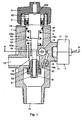
- the valve is formed by a tubular body (1) which has at one end a high pressure gas inlet port (11) connectable to a storage bottle (not depicted) and on one side a medium or low pressure gas outlet port (12), connected to distribution means (not depicted) for distributing said gas to the expelling points.
- a longitudinal housing (13) in which a shiftable actuator (2) is assembled.
- Said housing (13) is open at one end, in which there is a lid (3), and at the opposite end it has an access of the shiftable actuator (2) towards a passage (14) of gas which communicates the inlet port (11) and the outlet port (12).
- the shiftable element (2) has in its middle part an expanded collar or plunger (21) with a gasket for tightness with the side wall and is blocked at the upper part by a closing collar (4), also with a gasket for tightness with respect to the contour of said shiftable actuator (2).
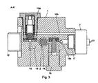
- the housing is divided into a first chamber (22) defined between the lid (3) and the assembly of the closing collar (4) and the effective surface (22a) of the end of the shiftable actuator (2), a second chamber (23) defined between the effective surface (23a), the plunger (21) of the shiftable actuator (2) and the bottom of the housing (13) and an intermediate chamber (24) defined between the mentioned plunger (21) and the closing collar (4), this intermediate chamber (24) being communicated with the exterior through a ventilation passageway (15).
- a spring (5), coil spring or compression element coaxially arranged on the shiftable actuator (2) and supported against the inner effective surface (23a) of the plunger (21).
- the shiftable actuator (2) has at its end close to the inlet port (11) a plug (6), configured in front of the passage (14) of gas between both ports (11 and 12) and which can be coupled on a projecting seat (14a) of said passage (14).
- the plug (6) allows the opening of the passage (14) when the shiftable actuator (2) moves towards the inlet port (11), and the closing of the passage (14) when said shiftable actuator (2) moves in the opposite direction.
- This plug (6) is formed by a receptacle (61) coupled to the end of the shiftable actuator (2), there being a closing gasket (62) in its inner part for its coupling on the seat (14a) and a rear ring (63), this rear ring (63) having a variable section to define a passage which can be regulated with the seat (14a) in the event of opening of the valve.
- the body (1) of the valve has a first conduit defined by three passageways (16a, 16b and 16c), the first passageway (16a) being arranged between a high pressure point close to the gas inlet port (11) and an outer threaded seat (17).
- the second passageway (16b) is arranged between the threaded seat (17) and a check valve (16) for the passage of the pressurized fluid.
- the third passageway (16c) is between the check valve (16) and the first chamber (22).
- blocking means (7) defined by a standard trigger, with a perforable membrane (71) and striker means (72) which can be remotely operated, the rupture of the perforable membrane (71) enabling the passage of the gas at high pressure to the first chamber (22) and the opening of the valve.
- the chamber (22) is connected by means of a venting conduit (10) to the second passageway (16b) through an equalizing valve (10a), this equalizing valve (10a) being loaded with a spring to create a certain overpressure in the first chamber (22) with respect to the pressure in said second passageway (16b).
- This venting conduit (10) is an extension of the air transmission leading the third conduit (16c) to the equalizing valve (10a).
- the body (1) of the valve has a second direct conduit (19) between the second chamber (23) and the low or medium pressure outlet port (12), which enables, in an operative position of the valve, that in said second chamber (23) there is a pressure approximately equal to the low or medium exit pressure, whereby there is a regulating negative pressure on the shiftable actuator.
Landscapes
- Engineering & Computer Science (AREA)
- General Engineering & Computer Science (AREA)
- Mechanical Engineering (AREA)
- Health & Medical Sciences (AREA)
- Public Health (AREA)
- Business, Economics & Management (AREA)
- Emergency Management (AREA)
- Safety Valves (AREA)
- Fluid-Driven Valves (AREA)
Claims (12)
- Auslassventil für eine Löschanlage, besonders ein Ventil, welches aus einem Körper (1), mit einer Hochdruck-Eintrittsöffnung (11), welche mit einer Hochdruck-Löschgasquelle gekoppelt werden kann und einer Nieder- oder Mitteldruck-Austrittsöffnung (12), welche mit Verteilungsmitteln für die Verteilung des genannten Gases gekoppelt werden kann, gebildet ist, wobei sich ein Gasdurchgang (14) und ein Stopper (6) des genannten Durchgangs (14) zwischen beiden Öffnungen (11 und 12) befinden, wobei der genannte Stopper (6) durch einen verstellbaren Aktuator (2) zwischen zwei Stellungen zum Schließen, Öffnen und Regulieren des Gasausgangs verstellbar ist, wobei der Körper (1) Folgendes umfasst: eine erste Kammer (22), welche mit einer effektiven Druckfläche (22a) auf dem verstellbaren Aktuator (2) in Verbindung steht, und betriebsmäßig geeignet ist, um die Verstellung des Stoppers (6) mit einer Öffnungsbewegung zu bewirken, eine zweite Kammer (23), welche mit einer effektiven Druckfläche (23a) auf dem verstellbaren Aktuator (2) in Verbindung steht, wobei diese zweite Kammer (23) der ersten Kammer (22) gegenübersteht und betriebsmäßig geeignet ist, um den genannten Stopper (6) mit einer Schließbewegung zu verstellen, und gegebenenfalls eine Feder (5), um den verstellbaren Aktuator (2) in Richtung der Schließstellung des Gasdurchgangs (14) durch den Stopper (6) zu verstellen, dadurch gekennzeichnet, dass es Folgendes umfasst: - eine erste Leitung mit Passagen (16a, 16b, 16c), welche zwischen einem Punkt des Körpers (1) des Ventils, welcher einem Hochdruck ausgesetzt ist, und der ersten Kammer (22) angeordnet ist, wobei es in der genannten ersten Leitung von Außen bedienbare Blockierungsmittel (7) gibt, - eine zweite Leitung (19) zur durchgängigen Verbindung zwischen der zweiten Kammer (23) und der Nieder- und Mitteldruck-Austrittsöffnung (12); wobei die genannte erste Leitung in einer nicht betriebsbereiten Bedingung für das Schließen des Stoppers (6) durch die optionale Wirkung der Feder (5) und den Niederdruck auf der effektiven Druckfläche (22a) in der ersten Kammer (22) geeignet ist, und in einer Betriebsbedingung für das Öffnen des Stoppers (6) in dem Gasdurchgang durch die Druckerhöhung auf der effektiven Druckfläche (22a) in der ersten Kammer (22), wobei die Regulierung der Stellung des Stoppers (6) durch den Druck auf der effektiven Druckfläche (23a) des verstellbaren Aktuators (2) der zweiten Kammer (23) und die optionale Wirkung der genannten Feder (5) ermöglicht wird, und dass es ein Rückschlagventil (16) in den Passagen (16a, 16b, 16c) der ersten Leitung des unidirektionalen Strömungsdruckkreislaufs zwischen einem Hochdruckpunkt und der Kammer (22), und eine Druckabführungsleitung (10) der genannten Kammer (22) durch ein mit einem federbelasteten Ausgleichsventil (10a) zur Festlegung des gesteuerten Überdrucks in der genannten Kammer (22) umfasst, und dass der Stopper (6) in einer Schließstellung vor einem im Gasdurchgang (14) ausgebildeten Sitz (14a) angeordnet ist, wobei der genannte Stopper (6) dazu geeignet ist, in einer Betriebsposition zur zwischen der Hochdrucköffnung und dem genannten Sitz (14a) definierten Hochdruckfläche verstellt zu werden.
- Ventil nach Anspruch 1, dadurch gekennzeichnet, dass die Blockierungsmittel (7) der ersten Leitung aus einer perforierbaren Membran (71) und Schlagmitteln (72), um diese von einer Femvorrichtung aus durchzubrechen, gebildet sind, wobei der Durchgang eines Hochdruckgases zur ersten Kammer (22) in einer Betriebsstellung des Ventils ermöglicht wird.
- Ventil nach Anspruch 2, dadurch gekennzeichnet, dass die perforierbare Membran (71) und die Schlagmittel (72) auf einem Gewindesitz (17) des Körpers (1) des Ventils angeordnet sind.
- Ventil nach Anspruch 1, dadurch gekennzeichnet, dass die erste Leitung einer Sicherheitsvorrichtung (8) gegen Überdruck (8), welche bei einem Hochdruckpunkt vor den Blockierungsmitteln (7) verbunden ist, zugeordnet ist.
- Ventil nach Anspruch 1, dadurch gekennzeichnet, dass der verstellbare Aktuator (2) in einem länglichen Gehäuse (13) des Körpers (1) für dessen Verstellung angeordnet ist, wobei die erste Kammer (22) und die zweite Kammer (23) in dem genannten Gehäuse (13) definiert sind.
- Ventil nach Anspruch 1, dadurch gekennzeichnet, dass die Feder (5) eine auf dem verstellbaren Aktuator (2) gelagerte Schraubenfeder ist.
- Ventil nach Anspruch 6, dadurch gekennzeichnet, dass die Feder im Inneren der zweiten Kammer (23) gelagert ist.
- Ventil nach Anspruch 6, dadurch gekennzeichnet, dass der Körper (1) einen oberen Deckel (3) für den Zugang zu dem Gehäuse des verstellbaren Aktuators (2) umfasst.
- Ventil nach Anspruch 5, dadurch gekennzeichnet, dass der verstellbare Aktuator (2) seitlich durch einen auf dem Körper (1) des Ventils geschraubten Schließring (4) befestigt ist, wobei die erste Kammer (22) von einer Zwischenkammer (24) dichtend getrennt wird.
- Ventil nach Anspruch 9, dadurch gekennzeichnet, dass die Zwischenkammer (24) mit dem Äußeren des Körpers (1) des Ventils mittels einer Lüftungspassage (15) in Verbindung steht.
- Ventil nach Anspruch 1, dadurch gekennzeichnet, dass der Stopper (6) aus einem auf einem Ende des verstellbaren Aktuators (2) gekoppelten Gefäß (61) gebildet ist und welcher eine Schließfuge (62) und einen hinteren Ring (63) mit variablem Querschnitt aufweist, um den Strömungsabschnitt des Gases auf den Sitz (14a) des Durchgangs (14) einzustellen.
- Ventil nach Anspruch 11, dadurch gekennzeichnet, dass der Sitz (14a) der Durchgangsfläche (14) einen vorspringenden Flansch für die Versiegelung gegen die Schließfuge (62) des Stoppers (6) aufweist.
Applications Claiming Priority (1)
| Application Number | Priority Date | Filing Date | Title |
|---|---|---|---|
| ES200900517U ES1070013Y (es) | 2009-03-17 | 2009-03-17 | Valvula de descarga para sistema de extincion |
Publications (2)
| Publication Number | Publication Date |
|---|---|
| EP2241794A1 EP2241794A1 (de) | 2010-10-20 |
| EP2241794B1 true EP2241794B1 (de) | 2012-05-09 |
Family
ID=40723312
Family Applications (1)
| Application Number | Title | Priority Date | Filing Date |
|---|---|---|---|
| EP10002743A Active EP2241794B1 (de) | 2009-03-17 | 2010-03-16 | Auslassventil für ein Löschsystem |
Country Status (3)
| Country | Link |
|---|---|
| EP (1) | EP2241794B1 (de) |
| AT (1) | ATE557223T1 (de) |
| ES (2) | ES1070013Y (de) |
Families Citing this family (5)
| Publication number | Priority date | Publication date | Assignee | Title |
|---|---|---|---|---|
| CN104455562A (zh) * | 2014-12-19 | 2015-03-25 | 艾赛孚消防科技(天津)有限公司 | 用于惰性混合气体灭火系统的低压稳流释放容器阀 |
| WO2015188284A2 (de) * | 2015-04-09 | 2015-12-17 | Taconova Group AG | Ventil für die verwendung im zu- oder rücklauf eines wasserkreislaufs zum heizen oder kühlen |
| ES1143033Y (es) | 2015-08-06 | 2015-11-26 | Residuos Y Gas Systems S L | Válvula de flujo constante para instalaciones de protección contra incendios. |
| DE102017110380A1 (de) * | 2017-05-12 | 2018-11-15 | Avl List Gmbh | Ablassventil für hohe Drücke |
| CN107327580B (zh) * | 2017-06-28 | 2019-04-26 | 扬中市第一蝶阀厂有限公司 | 一种抗冲刷的调节阀 |
Family Cites Families (3)
| Publication number | Priority date | Publication date | Assignee | Title |
|---|---|---|---|---|
| BR7404428A (pt) * | 1974-05-30 | 1976-02-03 | M Thomas | Valvula para controle de fluxo de gases sob alta pressao aplicavel a recipientes (cilindros) ou tubulacoes |
| US6871802B2 (en) | 2003-02-27 | 2005-03-29 | Fike Corporation | Self-modulating inert gas fire suppression system |
| DE602005018686D1 (de) * | 2005-04-13 | 2010-02-11 | Siemens Sas | Ventileinstelleinrichtung für feuerlöschsysteme |
-
2009
- 2009-03-17 ES ES200900517U patent/ES1070013Y/es not_active Expired - Fee Related
-
2010
- 2010-03-16 ES ES10002743T patent/ES2385139T3/es active Active
- 2010-03-16 EP EP10002743A patent/EP2241794B1/de active Active
- 2010-03-16 AT AT10002743T patent/ATE557223T1/de active
Also Published As
| Publication number | Publication date |
|---|---|
| EP2241794A1 (de) | 2010-10-20 |
| ES1070013Y (es) | 2009-10-05 |
| ATE557223T1 (de) | 2012-05-15 |
| ES2385139T3 (es) | 2012-07-18 |
| ES1070013U (es) | 2009-06-02 |
Similar Documents
| Publication | Publication Date | Title |
|---|---|---|
| CN100402156C (zh) | 阀单元及具有该阀单元的危险抑制系统 | |
| US10907749B2 (en) | Solenoid valve for controlling fluid | |
| EP2241794B1 (de) | Auslassventil für ein Löschsystem | |
| CN102883782B (zh) | 阀门 | |
| IL188014A0 (en) | Diaphragm latch valve | |
| US20160084394A1 (en) | Noise reduction relief valve for cryogenic liquid containers | |
| WO2009010177A1 (en) | Safety valve for releasing gas in overpressure, particularly for lpg vehicles propulsion apparatus | |
| US20190168607A1 (en) | Ventilation flow rate regulator for a pressurised tank of a vehicle | |
| EP2165099B1 (de) | Flüssigkeitskontollierte betätigungsvorrichtung eines selbstschliessenden absperrventils | |
| US7677262B2 (en) | Safety valve of a high pressure storage, in particular a hydrogen storage tank | |
| US5209253A (en) | Emergency shutoff valve and regulator assembly | |
| AU2013225962B2 (en) | Pneumatic gate valve with integrated pressurized gas reservoir | |
| EP1803488A1 (de) | Feuerlöschvorrichtung mit Löschmittelbehälter sowie entsprechende Druckgasflasche | |
| US3580274A (en) | Combined pressurizing and relief valve for fire extinguishers | |
| US8079567B2 (en) | Regulated valve assembly for fire extinguishing systems | |
| EP3128388B1 (de) | Konstantflussventil für feuerschutzinstallationen | |
| EP3983091B1 (de) | Manueller rücksetzaktuator | |
| KR101491837B1 (ko) | 지연 밸브 | |
| JP2013013478A (ja) | 乾式流水検知装置 | |
| JP2023095315A (ja) | 水没検知遮断装置 | |
| US20120193557A1 (en) | Shutoff fitting | |
| JPH07317933A (ja) | スプール型噴出防止弁 | |
| JP2009017997A (ja) | 流水検知装置および一斉開放弁 | |
| HK1118324B (en) | Self-modulating inert gas gire suppression system |
Legal Events
| Date | Code | Title | Description |
|---|---|---|---|
| PUAI | Public reference made under article 153(3) epc to a published international application that has entered the european phase |
Free format text: ORIGINAL CODE: 0009012 |
|
| AK | Designated contracting states |
Kind code of ref document: A1 Designated state(s): AT BE BG CH CY CZ DE DK EE ES FI FR GB GR HR HU IE IS IT LI LT LU LV MC MK MT NL NO PL PT RO SE SI SK SM TR |
|
| AX | Request for extension of the european patent |
Extension state: AL BA ME RS |
|
| 17P | Request for examination filed |
Effective date: 20110324 |
|
| GRAP | Despatch of communication of intention to grant a patent |
Free format text: ORIGINAL CODE: EPIDOSNIGR1 |
|
| RIC1 | Information provided on ipc code assigned before grant |
Ipc: F16K 31/42 20060101AFI20110915BHEP |
|
| RIN1 | Information on inventor provided before grant (corrected) |
Inventor name: PEREZ, CARLOS Inventor name: POZO, ALFONSO |
|
| GRAS | Grant fee paid |
Free format text: ORIGINAL CODE: EPIDOSNIGR3 |
|
| GRAA | (expected) grant |
Free format text: ORIGINAL CODE: 0009210 |
|
| AK | Designated contracting states |
Kind code of ref document: B1 Designated state(s): AT BE BG CH CY CZ DE DK EE ES FI FR GB GR HR HU IE IS IT LI LT LU LV MC MK MT NL NO PL PT RO SE SI SK SM TR |
|
| REG | Reference to a national code |
Ref country code: GB Ref legal event code: FG4D |
|
| REG | Reference to a national code |
Ref country code: AT Ref legal event code: REF Ref document number: 557223 Country of ref document: AT Kind code of ref document: T Effective date: 20120515 Ref country code: CH Ref legal event code: EP |
|
| REG | Reference to a national code |
Ref country code: IE Ref legal event code: FG4D |
|
| REG | Reference to a national code |
Ref country code: DE Ref legal event code: R096 Ref document number: 602010001284 Country of ref document: DE Effective date: 20120705 |
|
| REG | Reference to a national code |
Ref country code: ES Ref legal event code: FG2A Ref document number: 2385139 Country of ref document: ES Kind code of ref document: T3 Effective date: 20120718 |
|
| REG | Reference to a national code |
Ref country code: NL Ref legal event code: VDEP Effective date: 20120509 |
|
| REG | Reference to a national code |
Ref country code: LT Ref legal event code: MG4D Effective date: 20120509 |
|
| PG25 | Lapsed in a contracting state [announced via postgrant information from national office to epo] |
Ref country code: FI Free format text: LAPSE BECAUSE OF FAILURE TO SUBMIT A TRANSLATION OF THE DESCRIPTION OR TO PAY THE FEE WITHIN THE PRESCRIBED TIME-LIMIT Effective date: 20120509 Ref country code: LT Free format text: LAPSE BECAUSE OF FAILURE TO SUBMIT A TRANSLATION OF THE DESCRIPTION OR TO PAY THE FEE WITHIN THE PRESCRIBED TIME-LIMIT Effective date: 20120509 Ref country code: PL Free format text: LAPSE BECAUSE OF FAILURE TO SUBMIT A TRANSLATION OF THE DESCRIPTION OR TO PAY THE FEE WITHIN THE PRESCRIBED TIME-LIMIT Effective date: 20120509 Ref country code: SE Free format text: LAPSE BECAUSE OF FAILURE TO SUBMIT A TRANSLATION OF THE DESCRIPTION OR TO PAY THE FEE WITHIN THE PRESCRIBED TIME-LIMIT Effective date: 20120509 Ref country code: NO Free format text: LAPSE BECAUSE OF FAILURE TO SUBMIT A TRANSLATION OF THE DESCRIPTION OR TO PAY THE FEE WITHIN THE PRESCRIBED TIME-LIMIT Effective date: 20120809 Ref country code: CY Free format text: LAPSE BECAUSE OF FAILURE TO SUBMIT A TRANSLATION OF THE DESCRIPTION OR TO PAY THE FEE WITHIN THE PRESCRIBED TIME-LIMIT Effective date: 20120509 Ref country code: IS Free format text: LAPSE BECAUSE OF FAILURE TO SUBMIT A TRANSLATION OF THE DESCRIPTION OR TO PAY THE FEE WITHIN THE PRESCRIBED TIME-LIMIT Effective date: 20120909 |
|
| REG | Reference to a national code |
Ref country code: AT Ref legal event code: MK05 Ref document number: 557223 Country of ref document: AT Kind code of ref document: T Effective date: 20120509 |
|
| PG25 | Lapsed in a contracting state [announced via postgrant information from national office to epo] |
Ref country code: SI Free format text: LAPSE BECAUSE OF FAILURE TO SUBMIT A TRANSLATION OF THE DESCRIPTION OR TO PAY THE FEE WITHIN THE PRESCRIBED TIME-LIMIT Effective date: 20120509 Ref country code: GR Free format text: LAPSE BECAUSE OF FAILURE TO SUBMIT A TRANSLATION OF THE DESCRIPTION OR TO PAY THE FEE WITHIN THE PRESCRIBED TIME-LIMIT Effective date: 20120810 Ref country code: LV Free format text: LAPSE BECAUSE OF FAILURE TO SUBMIT A TRANSLATION OF THE DESCRIPTION OR TO PAY THE FEE WITHIN THE PRESCRIBED TIME-LIMIT Effective date: 20120509 Ref country code: PT Free format text: LAPSE BECAUSE OF FAILURE TO SUBMIT A TRANSLATION OF THE DESCRIPTION OR TO PAY THE FEE WITHIN THE PRESCRIBED TIME-LIMIT Effective date: 20120910 Ref country code: HR Free format text: LAPSE BECAUSE OF FAILURE TO SUBMIT A TRANSLATION OF THE DESCRIPTION OR TO PAY THE FEE WITHIN THE PRESCRIBED TIME-LIMIT Effective date: 20120509 |
|
| PG25 | Lapsed in a contracting state [announced via postgrant information from national office to epo] |
Ref country code: BE Free format text: LAPSE BECAUSE OF FAILURE TO SUBMIT A TRANSLATION OF THE DESCRIPTION OR TO PAY THE FEE WITHIN THE PRESCRIBED TIME-LIMIT Effective date: 20120509 |
|
| PG25 | Lapsed in a contracting state [announced via postgrant information from national office to epo] |
Ref country code: EE Free format text: LAPSE BECAUSE OF FAILURE TO SUBMIT A TRANSLATION OF THE DESCRIPTION OR TO PAY THE FEE WITHIN THE PRESCRIBED TIME-LIMIT Effective date: 20120509 Ref country code: NL Free format text: LAPSE BECAUSE OF FAILURE TO SUBMIT A TRANSLATION OF THE DESCRIPTION OR TO PAY THE FEE WITHIN THE PRESCRIBED TIME-LIMIT Effective date: 20120509 Ref country code: CZ Free format text: LAPSE BECAUSE OF FAILURE TO SUBMIT A TRANSLATION OF THE DESCRIPTION OR TO PAY THE FEE WITHIN THE PRESCRIBED TIME-LIMIT Effective date: 20120509 Ref country code: AT Free format text: LAPSE BECAUSE OF FAILURE TO SUBMIT A TRANSLATION OF THE DESCRIPTION OR TO PAY THE FEE WITHIN THE PRESCRIBED TIME-LIMIT Effective date: 20120509 Ref country code: DK Free format text: LAPSE BECAUSE OF FAILURE TO SUBMIT A TRANSLATION OF THE DESCRIPTION OR TO PAY THE FEE WITHIN THE PRESCRIBED TIME-LIMIT Effective date: 20120509 Ref country code: SK Free format text: LAPSE BECAUSE OF FAILURE TO SUBMIT A TRANSLATION OF THE DESCRIPTION OR TO PAY THE FEE WITHIN THE PRESCRIBED TIME-LIMIT Effective date: 20120509 Ref country code: RO Free format text: LAPSE BECAUSE OF FAILURE TO SUBMIT A TRANSLATION OF THE DESCRIPTION OR TO PAY THE FEE WITHIN THE PRESCRIBED TIME-LIMIT Effective date: 20120509 |
|
| PLBI | Opposition filed |
Free format text: ORIGINAL CODE: 0009260 |
|
| 26 | Opposition filed |
Opponent name: SIEMENS AKTIENGESELLSCHAFT Effective date: 20130211 |
|
| PLAX | Notice of opposition and request to file observation + time limit sent |
Free format text: ORIGINAL CODE: EPIDOSNOBS2 |
|
| REG | Reference to a national code |
Ref country code: DE Ref legal event code: R026 Ref document number: 602010001284 Country of ref document: DE Effective date: 20130211 |
|
| PG25 | Lapsed in a contracting state [announced via postgrant information from national office to epo] |
Ref country code: BG Free format text: LAPSE BECAUSE OF FAILURE TO SUBMIT A TRANSLATION OF THE DESCRIPTION OR TO PAY THE FEE WITHIN THE PRESCRIBED TIME-LIMIT Effective date: 20120809 |
|
| PLBB | Reply of patent proprietor to notice(s) of opposition received |
Free format text: ORIGINAL CODE: EPIDOSNOBS3 |
|
| PLAB | Opposition data, opponent's data or that of the opponent's representative modified |
Free format text: ORIGINAL CODE: 0009299OPPO |
|
| R26 | Opposition filed (corrected) |
Opponent name: SIEMENS AG/DE/SIEMENS SAS/FR Effective date: 20130211 |
|
| PLAB | Opposition data, opponent's data or that of the opponent's representative modified |
Free format text: ORIGINAL CODE: 0009299OPPO |
|
| R26 | Opposition filed (corrected) |
Opponent name: SIEMENS AG/DE/SIEMENS SAS/FR Effective date: 20130211 |
|
| PGFP | Annual fee paid to national office [announced via postgrant information from national office to epo] |
Ref country code: MC Payment date: 20150305 Year of fee payment: 6 |
|
| PG25 | Lapsed in a contracting state [announced via postgrant information from national office to epo] |
Ref country code: SM Free format text: LAPSE BECAUSE OF FAILURE TO SUBMIT A TRANSLATION OF THE DESCRIPTION OR TO PAY THE FEE WITHIN THE PRESCRIBED TIME-LIMIT Effective date: 20120509 |
|
| PG25 | Lapsed in a contracting state [announced via postgrant information from national office to epo] |
Ref country code: LU Free format text: LAPSE BECAUSE OF NON-PAYMENT OF DUE FEES Effective date: 20130316 Ref country code: MK Free format text: LAPSE BECAUSE OF FAILURE TO SUBMIT A TRANSLATION OF THE DESCRIPTION OR TO PAY THE FEE WITHIN THE PRESCRIBED TIME-LIMIT Effective date: 20120509 Ref country code: HU Free format text: LAPSE BECAUSE OF FAILURE TO SUBMIT A TRANSLATION OF THE DESCRIPTION OR TO PAY THE FEE WITHIN THE PRESCRIBED TIME-LIMIT; INVALID AB INITIO Effective date: 20100316 |
|
| REG | Reference to a national code |
Ref country code: FR Ref legal event code: PLFP Year of fee payment: 7 |
|
| PLCK | Communication despatched that opposition was rejected |
Free format text: ORIGINAL CODE: EPIDOSNREJ1 |
|
| REG | Reference to a national code |
Ref country code: DE Ref legal event code: R100 Ref document number: 602010001284 Country of ref document: DE |
|
| PG25 | Lapsed in a contracting state [announced via postgrant information from national office to epo] |
Ref country code: MC Free format text: LAPSE BECAUSE OF NON-PAYMENT OF DUE FEES Effective date: 20160331 |
|
| PGFP | Annual fee paid to national office [announced via postgrant information from national office to epo] |
Ref country code: MT Payment date: 20150312 Year of fee payment: 6 |
|
| PLBN | Opposition rejected |
Free format text: ORIGINAL CODE: 0009273 |
|
| STAA | Information on the status of an ep patent application or granted ep patent |
Free format text: STATUS: OPPOSITION REJECTED |
|
| 27O | Opposition rejected |
Effective date: 20160925 |
|
| REG | Reference to a national code |
Ref country code: FR Ref legal event code: PLFP Year of fee payment: 8 |
|
| PGFP | Annual fee paid to national office [announced via postgrant information from national office to epo] |
Ref country code: CH Payment date: 20170327 Year of fee payment: 8 |
|
| PGFP | Annual fee paid to national office [announced via postgrant information from national office to epo] |
Ref country code: BE Payment date: 20170213 Year of fee payment: 8 |
|
| PGFP | Annual fee paid to national office [announced via postgrant information from national office to epo] |
Ref country code: TR Payment date: 20170306 Year of fee payment: 8 |
|
| PG25 | Lapsed in a contracting state [announced via postgrant information from national office to epo] |
Ref country code: MT Free format text: LAPSE BECAUSE OF NON-PAYMENT OF DUE FEES Effective date: 20160331 |
|
| PGFP | Annual fee paid to national office [announced via postgrant information from national office to epo] |
Ref country code: ES Payment date: 20170328 Year of fee payment: 8 |
|
| REG | Reference to a national code |
Ref country code: FR Ref legal event code: PLFP Year of fee payment: 9 |
|
| PG25 | Lapsed in a contracting state [announced via postgrant information from national office to epo] |
Ref country code: MT Free format text: LAPSE BECAUSE OF NON-PAYMENT OF DUE FEES Effective date: 20160316 |
|
| REG | Reference to a national code |
Ref country code: CH Ref legal event code: PL |
|
| REG | Reference to a national code |
Ref country code: IE Ref legal event code: MM4A |
|
| PG25 | Lapsed in a contracting state [announced via postgrant information from national office to epo] |
Ref country code: IE Free format text: LAPSE BECAUSE OF NON-PAYMENT OF DUE FEES Effective date: 20180316 |
|
| PG25 | Lapsed in a contracting state [announced via postgrant information from national office to epo] |
Ref country code: LI Free format text: LAPSE BECAUSE OF NON-PAYMENT OF DUE FEES Effective date: 20180331 Ref country code: CH Free format text: LAPSE BECAUSE OF NON-PAYMENT OF DUE FEES Effective date: 20180331 |
|
| REG | Reference to a national code |
Ref country code: ES Ref legal event code: FD2A Effective date: 20190911 |
|
| PG25 | Lapsed in a contracting state [announced via postgrant information from national office to epo] |
Ref country code: ES Free format text: LAPSE BECAUSE OF NON-PAYMENT OF DUE FEES Effective date: 20180317 |
|
| PG25 | Lapsed in a contracting state [announced via postgrant information from national office to epo] |
Ref country code: TR Free format text: LAPSE BECAUSE OF NON-PAYMENT OF DUE FEES Effective date: 20180316 |
|
| PGFP | Annual fee paid to national office [announced via postgrant information from national office to epo] |
Ref country code: GB Payment date: 20260319 Year of fee payment: 17 |
|
| PGFP | Annual fee paid to national office [announced via postgrant information from national office to epo] |
Ref country code: DE Payment date: 20260320 Year of fee payment: 17 |
|
| PGFP | Annual fee paid to national office [announced via postgrant information from national office to epo] |
Ref country code: IT Payment date: 20260320 Year of fee payment: 17 |
|
| PGFP | Annual fee paid to national office [announced via postgrant information from national office to epo] |
Ref country code: FR Payment date: 20260323 Year of fee payment: 17 |