EP2241842A2 - Wärmekollektor - Google Patents
Wärmekollektor Download PDFInfo
- Publication number
- EP2241842A2 EP2241842A2 EP10159944A EP10159944A EP2241842A2 EP 2241842 A2 EP2241842 A2 EP 2241842A2 EP 10159944 A EP10159944 A EP 10159944A EP 10159944 A EP10159944 A EP 10159944A EP 2241842 A2 EP2241842 A2 EP 2241842A2
- Authority
- EP
- European Patent Office
- Prior art keywords
- collector
- heat
- water barrier
- insulating plate
- transfer conduit
- Prior art date
- Legal status (The legal status is an assumption and is not a legal conclusion. Google has not performed a legal analysis and makes no representation as to the accuracy of the status listed.)
- Granted
Links
- XLYOFNOQVPJJNP-UHFFFAOYSA-N water Substances O XLYOFNOQVPJJNP-UHFFFAOYSA-N 0.000 claims abstract description 50
- 230000004888 barrier function Effects 0.000 claims abstract description 49
- 230000000007 visual effect Effects 0.000 claims abstract description 7
- 230000005855 radiation Effects 0.000 claims abstract description 5
- 239000000463 material Substances 0.000 claims description 17
- 230000008878 coupling Effects 0.000 claims description 13
- 238000010168 coupling process Methods 0.000 claims description 13
- 238000005859 coupling reaction Methods 0.000 claims description 13
- 229910052751 metal Inorganic materials 0.000 claims description 12
- 239000002184 metal Substances 0.000 claims description 12
- 239000010426 asphalt Substances 0.000 claims description 9
- 239000006260 foam Substances 0.000 claims description 9
- 229920002943 EPDM rubber Polymers 0.000 claims description 8
- 229920005830 Polyurethane Foam Polymers 0.000 claims description 6
- 239000004411 aluminium Substances 0.000 claims description 6
- 229910052782 aluminium Inorganic materials 0.000 claims description 6
- XAGFODPZIPBFFR-UHFFFAOYSA-N aluminium Chemical compound [Al] XAGFODPZIPBFFR-UHFFFAOYSA-N 0.000 claims description 6
- 229920000582 polyisocyanurate Polymers 0.000 claims description 6
- 239000011495 polyisocyanurate Substances 0.000 claims description 6
- 229920006327 polystyrene foam Polymers 0.000 claims description 6
- 239000011496 polyurethane foam Substances 0.000 claims description 6
- RYGMFSIKBFXOCR-UHFFFAOYSA-N Copper Chemical compound [Cu] RYGMFSIKBFXOCR-UHFFFAOYSA-N 0.000 claims description 5
- 229910052802 copper Inorganic materials 0.000 claims description 5
- 239000010949 copper Substances 0.000 claims description 5
- 229920000642 polymer Polymers 0.000 claims description 5
- 239000004793 Polystyrene Substances 0.000 claims description 3
- 239000011888 foil Substances 0.000 claims description 3
- 239000012774 insulation material Substances 0.000 claims description 3
- 239000004800 polyvinyl chloride Substances 0.000 claims description 3
- 230000002745 absorbent Effects 0.000 claims description 2
- 239000002250 absorbent Substances 0.000 claims description 2
- 238000010521 absorption reaction Methods 0.000 description 10
- 238000009434 installation Methods 0.000 description 10
- 239000011162 core material Substances 0.000 description 4
- 239000003673 groundwater Substances 0.000 description 4
- 238000010438 heat treatment Methods 0.000 description 4
- 229920003023 plastic Polymers 0.000 description 4
- 239000004033 plastic Substances 0.000 description 4
- 239000011248 coating agent Substances 0.000 description 3
- 238000000576 coating method Methods 0.000 description 3
- 238000010276 construction Methods 0.000 description 3
- 238000001816 cooling Methods 0.000 description 3
- 238000009413 insulation Methods 0.000 description 3
- 238000004519 manufacturing process Methods 0.000 description 3
- LYCAIKOWRPUZTN-UHFFFAOYSA-N Ethylene glycol Chemical compound OCCO LYCAIKOWRPUZTN-UHFFFAOYSA-N 0.000 description 2
- 230000001143 conditioned effect Effects 0.000 description 2
- 239000011810 insulating material Substances 0.000 description 2
- 239000007788 liquid Substances 0.000 description 2
- 239000000203 mixture Substances 0.000 description 2
- 238000011084 recovery Methods 0.000 description 2
- 230000008439 repair process Effects 0.000 description 2
- 238000007789 sealing Methods 0.000 description 2
- RZVAJINKPMORJF-UHFFFAOYSA-N Acetaminophen Chemical compound CC(=O)NC1=CC=C(O)C=C1 RZVAJINKPMORJF-UHFFFAOYSA-N 0.000 description 1
- CWYNVVGOOAEACU-UHFFFAOYSA-N Fe2+ Chemical compound [Fe+2] CWYNVVGOOAEACU-UHFFFAOYSA-N 0.000 description 1
- 229910000831 Steel Inorganic materials 0.000 description 1
- WGLPBDUCMAPZCE-UHFFFAOYSA-N Trioxochromium Chemical compound O=[Cr](=O)=O WGLPBDUCMAPZCE-UHFFFAOYSA-N 0.000 description 1
- 239000000654 additive Substances 0.000 description 1
- 239000000853 adhesive Substances 0.000 description 1
- 230000001070 adhesive effect Effects 0.000 description 1
- 239000007798 antifreeze agent Substances 0.000 description 1
- 230000008901 benefit Effects 0.000 description 1
- 229910000423 chromium oxide Inorganic materials 0.000 description 1
- 230000007797 corrosion Effects 0.000 description 1
- 238000005260 corrosion Methods 0.000 description 1
- 229920001971 elastomer Polymers 0.000 description 1
- 239000000806 elastomer Substances 0.000 description 1
- 238000004146 energy storage Methods 0.000 description 1
- 230000002708 enhancing effect Effects 0.000 description 1
- 238000000605 extraction Methods 0.000 description 1
- 238000001125 extrusion Methods 0.000 description 1
- 239000011521 glass Substances 0.000 description 1
- WGCNASOHLSPBMP-UHFFFAOYSA-N hydroxyacetaldehyde Natural products OCC=O WGCNASOHLSPBMP-UHFFFAOYSA-N 0.000 description 1
- 238000007689 inspection Methods 0.000 description 1
- 230000010354 integration Effects 0.000 description 1
- 229910001512 metal fluoride Inorganic materials 0.000 description 1
- 229910044991 metal oxide Inorganic materials 0.000 description 1
- 150000004706 metal oxides Chemical class 0.000 description 1
- 150000002739 metals Chemical class 0.000 description 1
- 238000003801 milling Methods 0.000 description 1
- 230000004048 modification Effects 0.000 description 1
- 238000012986 modification Methods 0.000 description 1
- 150000004767 nitrides Chemical class 0.000 description 1
- 229920000728 polyester Polymers 0.000 description 1
- 229920000915 polyvinyl chloride Polymers 0.000 description 1
- 238000009417 prefabrication Methods 0.000 description 1
- 230000004044 response Effects 0.000 description 1
- 238000000926 separation method Methods 0.000 description 1
- 229910000679 solder Inorganic materials 0.000 description 1
- 239000010959 steel Substances 0.000 description 1
- 238000011179 visual inspection Methods 0.000 description 1
- 238000003466 welding Methods 0.000 description 1
Images


Classifications
-
- E—FIXED CONSTRUCTIONS
- E04—BUILDING
- E04D—ROOF COVERINGS; SKY-LIGHTS; GUTTERS; ROOF-WORKING TOOLS
- E04D3/00—Roof covering by making use of flat or curved slabs or stiff sheets
- E04D3/35—Roofing slabs or stiff sheets comprising two or more layers, e.g. for insulation
- E04D3/351—Roofing slabs or stiff sheets comprising two or more layers, e.g. for insulation at least one of the layers being composed of insulating material, e.g. fibre or foam material
- E04D3/355—Roofing slabs or stiff sheets comprising two or more layers, e.g. for insulation at least one of the layers being composed of insulating material, e.g. fibre or foam material the insulating layers of adjacent slabs having cooperating edges
-
- E—FIXED CONSTRUCTIONS
- E04—BUILDING
- E04D—ROOF COVERINGS; SKY-LIGHTS; GUTTERS; ROOF-WORKING TOOLS
- E04D3/00—Roof covering by making use of flat or curved slabs or stiff sheets
- E04D3/35—Roofing slabs or stiff sheets comprising two or more layers, e.g. for insulation
- E04D3/357—Roofing slabs or stiff sheets comprising two or more layers, e.g. for insulation comprising hollow cavities
-
- F—MECHANICAL ENGINEERING; LIGHTING; HEATING; WEAPONS; BLASTING
- F24—HEATING; RANGES; VENTILATING
- F24S—SOLAR HEAT COLLECTORS; SOLAR HEAT SYSTEMS
- F24S10/00—Solar heat collectors using working fluids
- F24S10/70—Solar heat collectors using working fluids the working fluids being conveyed through tubular absorbing conduits
- F24S10/75—Solar heat collectors using working fluids the working fluids being conveyed through tubular absorbing conduits with enlarged surfaces, e.g. with protrusions or corrugations
- F24S10/753—Solar heat collectors using working fluids the working fluids being conveyed through tubular absorbing conduits with enlarged surfaces, e.g. with protrusions or corrugations the conduits being parallel to each other
-
- F—MECHANICAL ENGINEERING; LIGHTING; HEATING; WEAPONS; BLASTING
- F24—HEATING; RANGES; VENTILATING
- F24S—SOLAR HEAT COLLECTORS; SOLAR HEAT SYSTEMS
- F24S20/00—Solar heat collectors specially adapted for particular uses or environments
- F24S20/60—Solar heat collectors integrated in fixed constructions, e.g. in buildings
- F24S20/67—Solar heat collectors integrated in fixed constructions, e.g. in buildings in the form of roof constructions
-
- F—MECHANICAL ENGINEERING; LIGHTING; HEATING; WEAPONS; BLASTING
- F24—HEATING; RANGES; VENTILATING
- F24S—SOLAR HEAT COLLECTORS; SOLAR HEAT SYSTEMS
- F24S80/00—Details, accessories or component parts of solar heat collectors not provided for in groups F24S10/00-F24S70/00
- F24S80/60—Thermal insulation
-
- F—MECHANICAL ENGINEERING; LIGHTING; HEATING; WEAPONS; BLASTING
- F24—HEATING; RANGES; VENTILATING
- F24S—SOLAR HEAT COLLECTORS; SOLAR HEAT SYSTEMS
- F24S70/00—Details of absorbing elements
- F24S70/20—Details of absorbing elements characterised by absorbing coatings; characterised by surface treatment for increasing absorption
-
- Y—GENERAL TAGGING OF NEW TECHNOLOGICAL DEVELOPMENTS; GENERAL TAGGING OF CROSS-SECTIONAL TECHNOLOGIES SPANNING OVER SEVERAL SECTIONS OF THE IPC; TECHNICAL SUBJECTS COVERED BY FORMER USPC CROSS-REFERENCE ART COLLECTIONS [XRACs] AND DIGESTS
- Y02—TECHNOLOGIES OR APPLICATIONS FOR MITIGATION OR ADAPTATION AGAINST CLIMATE CHANGE
- Y02A—TECHNOLOGIES FOR ADAPTATION TO CLIMATE CHANGE
- Y02A30/00—Adapting or protecting infrastructure or their operation
- Y02A30/60—Planning or developing urban green infrastructure
-
- Y—GENERAL TAGGING OF NEW TECHNOLOGICAL DEVELOPMENTS; GENERAL TAGGING OF CROSS-SECTIONAL TECHNOLOGIES SPANNING OVER SEVERAL SECTIONS OF THE IPC; TECHNICAL SUBJECTS COVERED BY FORMER USPC CROSS-REFERENCE ART COLLECTIONS [XRACs] AND DIGESTS
- Y02—TECHNOLOGIES OR APPLICATIONS FOR MITIGATION OR ADAPTATION AGAINST CLIMATE CHANGE
- Y02B—CLIMATE CHANGE MITIGATION TECHNOLOGIES RELATED TO BUILDINGS, e.g. HOUSING, HOUSE APPLIANCES OR RELATED END-USER APPLICATIONS
- Y02B10/00—Integration of renewable energy sources in buildings
- Y02B10/20—Solar thermal
-
- Y—GENERAL TAGGING OF NEW TECHNOLOGICAL DEVELOPMENTS; GENERAL TAGGING OF CROSS-SECTIONAL TECHNOLOGIES SPANNING OVER SEVERAL SECTIONS OF THE IPC; TECHNICAL SUBJECTS COVERED BY FORMER USPC CROSS-REFERENCE ART COLLECTIONS [XRACs] AND DIGESTS
- Y02—TECHNOLOGIES OR APPLICATIONS FOR MITIGATION OR ADAPTATION AGAINST CLIMATE CHANGE
- Y02E—REDUCTION OF GREENHOUSE GAS [GHG] EMISSIONS, RELATED TO ENERGY GENERATION, TRANSMISSION OR DISTRIBUTION
- Y02E10/00—Energy generation through renewable energy sources
- Y02E10/40—Solar thermal energy, e.g. solar towers
- Y02E10/44—Heat exchange systems
Definitions
- the present invention relates to a heat collector comprising at least one collector panel, comprising a foamed insulating plate body with a main surface on which at least one channel is provided which is open on the main surface, and comprising at least one collector element, comprising a heat-exchanging body which is situated at least partially on the main surface of the insulating plate body and is in heat-exchanging contact with a heat transfer conduit for a heat-carrying medium, the heat transfer conduit being situated at least substantially in the channel, wherein the collector element is arranged under a water barrier layer.
- the invention also relates to a roof construction.
- the invention also relates to a heat-collecting roof system comprising a roof with a roof surface on which a water barrier finishing layer is arranged.
- Heat collectors of the type stated in the preamble are applied on considerable scale as heat collector to produce energy in the form of heat from sunlight, and for this reason are also referred to as solar collector.
- These are often so-called flat plate collectors in the form of a collector panel in which a heat-exchanging body enters into heat-exchanging contact with a heat-carrying medium which is guided through a conduit provided for this purpose.
- the medium will be heated through thermal contact between the conduit and the heat-exchanging body if a temperature of the heat-exchanging body is higher than that of the medium, and energy transfer thus takes place. Conversely, the medium will relinquish energy to the heat-exchanging body if the temperature of the medium is higher than that of the heat-exchanging body.
- Such a system can for instance be applied in a closed circuit for more or less active extraction of heat from sunlight for the purpose of then exchanging this heat with a hot water appliance, for instance via a heat exchanger, in order to increase the overall efficiency of the appliance.
- a collector for for instance underground energy storage, wherein groundwater is heated or cooled according to the season and the thus heated or cooled groundwater is stored underground for the rest of the season in order to be pumped up in a subsequent season for heating respectively cooling of a building, such as a house, stable or a climate greenhouse.
- Such a heat and/or cold recovery can thus be utilized to cool buildings in summer, wherein use is made of the winter cold with which the groundwater has been cooled in winter, and conversely to heat buildings in winter, wherein the summer heat relinquished to the groundwater is utilized efficiently to reduce heating costs in winter.
- a collector element for such a heat collector is known from European patent application EP 1.217.315 .
- the known collector element comprises a substantially flat, strip-like heat-exchanging body of aluminium or other suitable metal, which is provided on a visual side with a heliothermal absorption layer in the form of a dark coating.
- a heat transfer conduit is connected mechanically to the heat-exchanging body and in heat-exchanging contact therewith, so that heat transfer can take place between the heat-exchanging body and a medium flowing through the heat transfer conduit during operation.
- the heat-exchanging body as heliothermal absorption layer comprises an advanced multilayer coating of successively a high-grade metal layer, a layer of chromium oxide and a top layer of a metal oxide, metal nitride or metal fluoride with an efficient refractive index.
- One or more of such collector elements are usually unified in a closed panel, which is provided on the visual side with a transparent glass cover.
- a drawback of many known heat collectors is their relatively high cost price, whereby an economic cost-recovery period thereof is lengthened. Not only are material, transport and production costs a factor here, installation costs also contribute not inconsiderably toward the investment necessary for the purpose. In addition, known collector panels are relatively heavy, which results in a significant roof load when they are incorporated into a roof of a building.
- a heat collector of the type described in the preamble is known from European patent application EP 1.512.922 .
- This known heat collector comprises a foamed insulating plate body having on a main surface thereof a series of parallel channels which open on the main surface. Protruding into the channels is a collector element with a corresponding number of hollow groove parts extending therefrom. Extending in the groove parts is a flexible heat transfer conduit which is clamped thereby. Between the groove parts the collector element is substantially plate-like and lies against the main surface under a water barrier layer which has been arranged thereover. During operation a heat-carrying medium flows through the heat transfer conduit in order to take up from the collector element solar heat captured thereby.
- this known heat collector only produces a small additional load on the roof owing to the application of a self-supporting foamed insulating plate body as a base therefor, this known construction has the drawback that a water-tightness thereof cannot be guaranteed. Due to constantly alternating heating and cooling of the water barrier layer and the collector element thereunder, both these parts will inevitably expand and contract, and in non-uniform manner. It is hereby not possible to prevent the collector element detaching from the insulating plate body and, in the extreme case, pulling loose the water barrier layer, with all the leakage consequences this entails. The known heat collector moreover also requires considerable installation work on site for connection to service pipes, which increases the cost price and again contributes toward the risk of leakage of the whole.
- the present invention has for its object, among others, to provide a heat collector which at least significantly obviates one or more of these drawbacks.
- a heat collector of the type described in the preamble has the feature according to the invention that the water barrier layer comprises a flexible watertight cover layer which extends laterally outside the collector element and which is adhered in leakproof manner to the main surface, and that the water barrier layer is suitable for absorbing heliothermal radiation and is in heat-exchanging contact with the collector element.
- an elastomer plastic and/or bitumen is preferably applied for the flexible cover layer.
- the heat transfer conduit is enclosed by insulating material in the insulating plate body so that the heat-exchanging body will exchange energy with the medium in the conduit in optimal manner, i.e. with little loss.
- the nature of the water barrier layer moreover also makes a significant contribution toward a high energy efficiency because it enhances optimal absorption of heliothermal radiation incident thereon. Because the water barrier layer also extends laterally of the collector element over the adjacent part of the main surface of the insulating plate body and is adhered thereto, a fixation of the collector element in the insulating plate body and a watertight sealing of the whole are achieved.
- the water barrier absorption layer thus provides for the desired absorption of incident heat radiation as well as a watertight sealing, whereby despite its relative simplicity and low weight the system is highly suitable as overall finish for outdoor applications. All in all, a relatively lightweight solution can thus be provided while maintaining high energy efficiency and flexibility.
- the heat collector according to the invention is characterized in that the collector panel comprises adjacently of the insulating plate body a gutter part with a continuous, at least substantially leakproof cavity for receiving at least one service pipe therein, and that the at least one heat transfer conduit protrudes into the cavity of the gutter part.
- the collector panel can be realized under fully controlled and conditioned prefabrication conditions together with the service pipes and couplings of the at least one collector element. A considerable part of the installation work, particularly the couplings between successive conduits and/or collector elements, can thus already be arranged and tested for liquid-tightness beforehand in a controlled production environment. The collector panel is thus assembled for at least the greater part as prefab module.
- the leakproof gutter part can moreover function as receptacle and drain so as to thus avoid damage to an underlying construction.
- the gutter can moreover be embodied and installed such that it can serve as overflow for rainwater for the purpose of supporting an existing rainwater drainage system in the unlikely event of a blockage in this latter.
- a particular embodiment of the heat collector has the feature according to the invention that the gutter part comprises a set of side walls on either side of the cavity which extend from a closed bottom and that a removable cover body is connected releasably to the side walls in order to close the cavity on a side remote from the bottom, and more particularly that the side walls and the bottom of the gutter part comprise at least a core of thermal insulation material.
- the gutter is thus also thermally insulated so that pipe losses from the service pipe are limited, and owing to the removable cover body the conduit ends of the heat transfer conduits remain accessible at all times for visual inspection and possible modification or repair.
- a further particular embodiment of the heat collector according to the invention is characterized in this respect in that the gutter part is provided on at least one end surface with coupling means for an at least substantially leakproof connection to an opposite end surface of a corresponding gutter part of a further collector panel.
- a further particular embodiment of the heat collector according to the invention has the feature here that a closing part is connected to the coupling means on the opposite end surface of the gutter part.
- a further preferred embodiment of the heat collector according to the invention has the feature that the water barrier layer comprises at least one sheet of a watertight foil, in particular of a roof covering material from a group of bitumen, polyolefin-copolymerisate-bitumen, polyvinyl chloride (PVC) and polymerized ethylene-propylene-diene monomer (EPDM), and preferably one of bitumen with EPDM rubber.
- a further preferred embodiment of the heat collector according to the invention has the feature that the water barrier layer is highly absorbent heliothermally at least on a visual side, is particularly black and more particularly deep black.
- a further preferred embodiment of the heat collector has the feature according to the invention that the insulating plate body comprises a number of collector elements on the main surface and that the water barrier layer extends over the number of collector elements.
- Such a shared covering is not only preferable from a production engineering viewpoint, it moreover results in an aesthetically attractive, optically continuous whole. Because the number of seams is thus limited, this furthermore contributes toward the reliability and durability of the system.
- a number of collector elements can be integrated within a collector panel.
- a particular embodiment of the heat collector according to the invention has the feature here that the insulating plate body comprises on the main surface a number of collector elements laterally separated from each other, and that the water barrier layer extends over the number of collector elements.
- the lateral division and separation of the individual collector elements here reduces the maximum pull and push caused thereby during heating and cooling of the system, and moreover provides an adhesion base for the water barrier layer on the main surface.
- a number of collector panels can moreover be integrated into a total heat-collecting roof system.
- a further particular embodiment of the heat collector according to the invention has the feature that the water barrier layer extends flat at least substantially over the whole main surface of the collector panel and protrudes on at least one side outside the collector panel. This protruding part thus provides a flashing of roof covering material which can be employed for a leakproof adhesion to the water barrier layer of an adjacent collector panel.
- An optically and mechanically continuous roof system in which a heat collector according to the invention is invisibly incorporated can thus be realized in exceptionally simple and reliable manner.
- the heat collector according to the invention has the feature that the heat transfer conduit and the heat-exchanging body are manufactured at least substantially from metal, in particular at least one metal taken from a group of aluminium and copper.
- the application of metal for both the heat-exchanging body and the conduit connected thereto produces a low heat resistance and provides for an excellent heat transfer.
- the diameter of the conduit can hereby remain relatively modest while a sufficient degree of heat exchange with the medium is nevertheless possible. This results in short relaxation or response times of the system, which is thereby able to react quickly to temperature differences.
- the total quantity of the medium can moreover be limited, whereby the system is easier to integrate into an existing climate control installation.
- metals are characterized by a relatively low thermal expansion coefficient, whereby successive collector elements need only maintain a small intermediate distance and a high degree of coverage can thus be achieved. This also contributes toward a high energy efficiency and operational capacity of the whole.
- the heat-exchanging body can be of varying nature and form, although a preferred embodiment of the heat collector according to the invention has the feature that the heat-exchanging body is at least substantially strip-like and is connected in a longitudinal direction in heat-exchanging contact to the heat transfer conduit.
- the strip-like body has for instance a width of several times a width of the conduit and thus allows integration with the insulating plate body in the same manner as the conduit.
- a particular embodiment of the heat collector according to the invention moreover has the feature here that the heat transfer conduit protrudes on either side outside the heat-exchanging body.
- the heat transfer conduit can thus be connected on a first side to a service pipe or a similar collector element, while the conduit can moreover be coupled on an opposite side to a similar, following collector element in longitudinal direction or one situated laterally adjacent thereof.
- a further preferred embodiment of the heat collector according to the invention has the feature that the heat transfer conduit comprises at least one U-turn under the heat-exchanging body, and in particular meanders thereunder.
- the collector element thus forms a relatively large connected whole which lies embedded as independent element in the insulating plate body.
- the heat collector is here further characterized in that the heat transfer conduit protrudes on one side outside the heat-exchanging body.
- the heat transfer conduit can thus be connected relatively easily at least on said side to for instance a set of service pipes.
- the heat collector according to the invention is however particularly characterized in this respect in that the insulating plate body is formed at least substantially from a polymer foam, taken particularly from a group of polyurethane foam (PUR), polystyrene foam (PS) and polyisocyanurate foam (PIR).
- PUR polyurethane foam
- PS polystyrene foam
- PIR polyisocyanurate foam
- Such polymer foams provide an excellent heat insulation and are moreover relatively lightweight owing to their relatively low density.
- use is particularly made here of an optionally laminated plate material of such a polymer foam of a high density to be able to sufficiently withstand a normal roof load. By avoiding a coating or other type of laminate on the back side, warping of the plate body is prevented when the temperature of the at least one collector element increases on the main surface.
- a further particular embodiment of the heat collector according to the invention has the feature that the insulating plate body is resilient at least adjacently of the at least one channel, and that the at least one channel has a width on the main surface which is smaller than a greatest width of the heat transfer conduit held therein.
- a collector element can thus be pressed with the heat transfer conduit into the channel which, owing to the resilience of the material used, will initially yield to some extent on the surface and then snap around the conduit. The collector element is thus fixed semi-permanently in the insulating plate body.
- a significant advantage of the heat collector according to the invention is that it can be extended relatively freely in lateral direction so as to thus enable an existing surface for covering to be filled in particularly efficient manner.
- a further particular embodiment of the heat collector according to the invention has the feature that the collector panel comprises a number of successively placed insulating plate bodies, the at least one channels of which lie mutually in line in order to receive therein a collector element with the heat transfer conduit. A sufficient number of insulating plate bodies can thus be successively connected for jointly receiving therein one or more collector elements, which extend here over the full length of the whole.
- the system according to the invention can also be extended in a width direction.
- a further particular embodiment of the heat collector has for this purpose the feature according to the invention that the collector panel connects laterally to at least one similar connector panel and that the water barrier layer of a collector panel extends partially over at least one adjacent panel.
- a total collector system can comprise an optimal number of collector panels in both the width and length, which panels are mutually interconnected in order to thus increase the heat-exchanging and overall energy capacity of the whole.
- the above described heat collector is hereby particularly suitable for roofs.
- a heat-collecting roof system of the type described in the preamble has in this respect the feature according to the invention that a heat collector as claimed in one or more of the foregoing claims is arranged on the roof surface, optionally with interposing of a vapour control layer, and that the heat collector comprises the water barrier finishing layer.
- the roof system is characterized here according to the invention in that the roof surface is flat to slightly inclining, with an angle of inclination of a maximum of about 30 degrees.
- FIG. 1 shows a collector element 10 of a first embodiment of a heat collector according to the invention.
- the collector element comprises in this case a strip-like heat-exchanging body 11 which is able and adapted to carry away captured solar heat or to relinquish heat to a surrounding area.
- On a back side strip-like body 11 is connected to a heat transfer conduit 15 intended and adapted to transport a heat-carrying medium.
- Both strip-like heat-exchanging body 11 and heat transfer conduit 15 are manufactured from metal because of their excellent heat-conducting properties. In this example a corrosion-resistant non-ferrous metal such as aluminium or copper is chosen here.
- Strip-like body 11 is formed specifically in this example from coated aluminium sheet, while use is made of a thin-walled copper conduit for the heat-carrying medium.
- the heat transfer conduit can be embodied with a profile or a relief on an inner wall thereof for the purpose of preventing a laminar flow along the inner wall, and precisely for increasing turbulence. The latter contributes further toward a good energetic heat exchange between the conduit on the one hand and the medium flowing therethrough on the other.
- Both parts 11,15 of collector element 10 are mutually connected by means of (spot) welding or adhesion, wherein in the latter case use is preferably made of an adhesive with a low heat resistance, for instance due to a significant metallic fraction in the composition thereof.
- spot welds 14 Use is made in this example of a series of spot welds 14 placed closely together which ensure a good heat-exchanging contact between the two parts 11,15.
- the heat collector according to the invention can suffice with a relatively small liquid volume and a relatively high flow rate of the medium can be maintained, whereby the system has an exceptionally short relaxation time and is able to respond quickly to temperature fluctuations.
- Collector element 10 typically has a length of several to more than ten metres and a width in the order of 5 to 20 centimetres. In this respect use is made in this example of a width of about 15 centimetres by a length of about four metres.
- Strip-like body 11 is here typically in the order of only several tenths of millimetres to several millimetres thick.
- heat transfer conduit 15 typically has a diameter in the order of 6 to 15 millimetres.
- heat transfer conduit 15 and heat-exchanging body 11 can optionally also be formed as one integral whole from a suitable metal, such as for instance aluminium, wherein an excellent heat-exchanging contact is ensured ab initio.
- the heat collector further comprises a plate-like insulating plate body 20 as shown by way of example in figures 2 and 4 .
- This insulating plate body 20 substantially comprises a foamed core 21 with a thickness in the order of about 5 to 15 centimetres, in this example about 12 centimetres, as according to the desired degree of thermal insulation, which is covered on both sides with a thin plastic foil (not further shown).
- PIR polyisocyanurate foam
- PS polystyrene foam
- PUR polyurethane foam
- plate material 20 is provided with a series of contour-formed channels 23 in which collector elements of the type shown in figure 1 are fittingly received with their heat transfer conduit 15.
- the collector elements are here glued into and adhered to insulating plate body 20.
- Channels 23 are for instance obtained by means of milling and are slightly narrower on main surface 21 than the diameter of heat transfer conduit 15, so that the latter snap into the channels and are then held fast with the freedom to thermally expand and contract.
- the insulating plate body 20 is provided with a tongued profile 25 or grooved profile 24 to enable a number of such collector panels to be combined fitting together to form a full collector if desired.
- a collector panel comprises one or more insulating plate bodies 20(1..4) which in the case of a plurality can be arranged successively in line in the manner shown in figures 3 and 5 , wherein the thus successive channels 23 jointly comprise a collector element 10 with a conduit 15 running therein.
- Heat transfer conduit 15 of collector element 10 is here at least substantially wholly countersunk and embedded in insulating material 21 of insulating plate body 20, and so adequately thermally insulated.
- the absorption bodies 11 of collector elements 10 are provided with a heliothermal absorption layer 12 to enable sunlight to be captured therein or heat to be relinquished to the surrounding area.
- the heliothermal absorption layer 12 comprises a water barrier layer which, while overlapping an adjacent part of the heat-exchanging body, is adhered in leakproof manner to main surface 22 of insulating plate body 20.
- Use can be made for this purpose of separate strips of a suitable water barrier composition and thickness which are individually connected in leakproof manner to insulating plate body 20 on either side of a collector element.
- Use is however advantageously made in this example of a continuous shared water barrier layer which has been arranged at least substantially over the whole main surface, see figures 5-7 .
- a dark, preferably (deep) black EPDM roof covering is a combination of bitumen and EPDM rubber.
- This layer is glued, fused or otherwise adhered to strip-like body 11 and the free part of main surface 22 of insulating plate body 20, and has a layer thickness of between 1 and 2.5 millimetres.
- another roof covering material such as polyvinylchloride or bitumen, can otherwise also be applied for water barrier layer 12.
- roof covering materials are generally available in varying thicknesses on a roll and combine excellent water barrier properties with a high heliothermally absorbing and adequate heat-transporting capacity.
- Use is made in this example of a roll width of about 100 or 110 centimetres, so that a free strip of about 10 centimetres remains laterally and on an end surface per insulating plate body 20 of 90 centimetres wide, and on site can be folded over an adjacent collector panel as flashing and adhered conventionally in leakproof manner.
- the water barrier top layer 12 contributes not inconsiderably toward the heat-collecting efficiency of collector panel 10, which heat can be exchanged via heat-exchanging body 11 with a heat-carrying medium flowing through heat transfer conduit 15 during operation.
- a heat-carrying medium flowing through heat transfer conduit 15 during operation.
- use is generally made of pure water, although use can also be made of other liquids such as for instance an oil, and additives can optionally be added to the water, such as particularly an antifreeze agent such as glycol.
- distal conduit ends 16 are mutually interconnected by means of conventional squeeze or solder couplings 17, see figure 7 .
- this always provides a whole number of pairs of respectively a feed and return conduit which, in accordance with the so-called Tichelman connecting principle presumed known to the skilled person, can for instance be coupled to three service pipes 41..43, see also figure 8 .
- a gutter part 30 is provided on the collector parts which provides space for these service pipes 41..43 and which can be closed off with a cover body adapted thereto, such as cover 31 shown in figure 8 .
- Conduits 15 of collector elements 10 here protrude with a proximal free outer end 18 into gutter part 30 for later coupling to such a service pipe 41..43 by means of a conventional squeeze coupling 17.
- Cover 31 is closed by means of rapid-action closing means, such as plastic screws or bayonets 35, onto a top side of gutter parts 30 and can therefore be easily removed manually without damage so as to allow at all times a later inspection or repair of pipes 41..43 and the connections made thereto.
- Gutter parts 30 are prefabricated from for instance polyester, another suitable plastic or preserved steel, wherein both cover 31, walls 32 and bottom 33 are thermally insulated since the same or similar insulating foam plate material is applied therefor as for insulating plate bodies 20. Thermal losses via the gutter parts can thus be limited effectively.
- the gutter parts have a fully watertight finish in order to collect and stem any leakage of a conduit system received or debouching therein.
- the collector panel 10 shown in figure 7 with gutter part 30 formed thereon forms a prefab element which is easily processed and which can be fully preassembled and tested beforehand under conditioned and controlled conditions.
- a desired number of such collector panels of a length adapted to a specific situation are combined up to a width adapted to this specific situation. This is illustrated in figure 7 for only two panels, but both the width and length can be extended further as required.
- Gutter parts 30 here lie mutually in line and thus form a total gutter which provides space for shared service pipes 40,41, see figure 8 , for a central feed and discharge of a heat-carrying medium.
- a complete collecting roof system can thus be delivered in relatively short (installation) time and with relatively little on-site installation work.
- a watertight and relatively vapour-tight roof covering is arranged as vapour barrier or vapour-regulating layer on an available surface or slightly inclining roof surface under the collector system
- the prefab collector panels of the heat collector are adhered or fixed mechanically to the vapour barrier layer.
- the water barrier layer of the heat collector according to the invention is the final watertight finishing layer of the roof surface. This layer thus functions as water barrier as well as for heat absorption or heat emission. Because the water barrier layer can be formed from a normal, dark, preferably black roof covering material, the collector system can thus be incorporated almost invisibly in a roof system.
- the installation thereof lies wholly within the skill and the normal expertise of roofers so that no specially trained personnel is required for the purpose.
- For the insulating plate bodies of the collector system use is preferably made of a polymer foam of a high density so that it is possible to walk normally on the system.
- the gutter assembled from gutter parts 30 can be placed at a highest point so that service pipes and collecting conduits can be vented therefrom in simple manner.
- the gutter parts can here be provided on their end surfaces with coupling means such as protrusions and cavities corresponding thereto for the purpose of enhancing a mutual alignment and a mutual connection of the whole.
- a free end surface of the final element is closed using an insulated end cover 35, which can in this case engage and co-act in similar manner with the same coupling means.
- Closing part 25 comprises for this purpose cavities at the position of connections 16,17 for fittingly receiving the connections therein.
- top layer 12 extends with a free flap 19, which is later adhered on site to closing part 25 to form an optically continuous whole. This side of the collector is thus also finished neatly and protected from weather influences and other external factors.
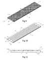
- a collector part of a second exemplary embodiment of a heat collector according to the invention is shown in figures 9-11 .
- the collector part is combined with a gutter part 30 and service pipes in similar manner as in the above described example, the content of which should be deemed as cited and included herein, unless expressly stated otherwise below.
- the collector part does not comprise a number of mutually adjacent, more or less separate collector elements, but instead a single collector element 10 with a plate-like heat-exchanging body 11 extending over substantially a whole surface of an insulating plate body lying thereunder.
- Insulating plate body 20 can herein be manufactured integrally, as here, or, as in the first exemplary embodiment, be assembled from successively placed individual parts.
- a continuous channel 23 Arranged on a main surface of the insulating plate body is a continuous channel 23 which meanders over the surface between U-turns 51,52 in order to receive fittingly therein a similarly formed heat transfer conduit 15 of the collector element.
- a copper conduit with a diameter in the order of 8-15 millimetres, in this case about 10 millimetres.
- the dense insulating foamed core material 21 of insulating plate body 20 also ensures in this case an excellent thermal insulation of the heat transfer conduit 15 thus substantially wholly enclosed thereby. Only at a proximal end surface does conduit 15 protrude with two proximal outer ends 18 outside the insulating plate body.
- the collector element can be connected therewith to service pipes for respectively feed and discharge of a heat-carrying medium, or optionally be laterally connected to a corresponding proximal outer end of an adjacent, similar collector part with which it is placed in series.
- a tongue and groove profile 24,25 provides, together with overhang 19 of bituminous water barrier top layer 12, for a substantially imperceptible lateral connection and extensibility of the whole.
- the length and width of the individual collector panels and a collector assembled therefrom can be freely adjusted within determined limits to an available surface to be covered therewith. These limits will be defined mainly from a viewpoint of logistics and transport. In the shown example use is typically made of a panel width of about 90 centimetres and a length in the order of 2-8 metres. This significantly greater panel length compared to the foregoing exemplary embodiment is required because the connections of the panel are situated on one side only, whereby the panel shown here is not suitable for interconnection of successive collector elements in a longitudinal direction. On the other hand however, the number of connections and couplings of conduits and collector elements can be kept considerably more limited in the present exemplary embodiment, which reduces the chance of leakage and saves assembly time and material.
- the described collector system is described mainly as a system which collects heliothermal heat in summer and during the day and transfers it to the medium being carried through the heat transfer conduit, the system is however also suitable for collecting cold in winter and during the night and transferring it to the medium for the purpose of (underground) storage for use at a later time, for instance to support a climate control installation in summer or during the day.
Landscapes
- Engineering & Computer Science (AREA)
- Chemical & Material Sciences (AREA)
- Sustainable Development (AREA)
- Sustainable Energy (AREA)
- Civil Engineering (AREA)
- General Engineering & Computer Science (AREA)
- Physics & Mathematics (AREA)
- Life Sciences & Earth Sciences (AREA)
- Architecture (AREA)
- Structural Engineering (AREA)
- Thermal Sciences (AREA)
- Combustion & Propulsion (AREA)
- Mechanical Engineering (AREA)
- Dispersion Chemistry (AREA)
- Roof Covering Using Slabs Or Stiff Sheets (AREA)
- Laminated Bodies (AREA)
Applications Claiming Priority (2)
| Application Number | Priority Date | Filing Date | Title |
|---|---|---|---|
| NL1036855A NL1036855C2 (nl) | 2009-04-15 | 2009-04-15 | Warmtecollector en warmte collecterende dakconstructie. |
| NL2003336A NL2003336C2 (nl) | 2009-04-15 | 2009-08-05 | Warmtecollector en warmte collecterende dakconstructie. |
Publications (3)
| Publication Number | Publication Date |
|---|---|
| EP2241842A2 true EP2241842A2 (de) | 2010-10-20 |
| EP2241842A3 EP2241842A3 (de) | 2011-06-15 |
| EP2241842B1 EP2241842B1 (de) | 2017-11-15 |
Family
ID=42395033
Family Applications (1)
| Application Number | Title | Priority Date | Filing Date |
|---|---|---|---|
| EP10159944.7A Not-in-force EP2241842B1 (de) | 2009-04-15 | 2010-04-14 | Wärmekollektor |
Country Status (2)
| Country | Link |
|---|---|
| EP (1) | EP2241842B1 (de) |
| NL (1) | NL2003336C2 (de) |
Cited By (3)
| Publication number | Priority date | Publication date | Assignee | Title |
|---|---|---|---|---|
| CN105115169A (zh) * | 2015-09-30 | 2015-12-02 | 江苏阳光四季新能源科技股份有限公司 | 一种无痕防腐抗冻高密封平板太阳能集热器及其制备方法 |
| CN110847511A (zh) * | 2019-12-05 | 2020-02-28 | 徐州天骋智能科技有限公司 | 一种隔热性能强的彩钢瓦 |
| EP3835683A1 (de) * | 2019-12-13 | 2021-06-16 | Fundación Tecnalia Research & Innovation | Modulares wärmeübertragungshydrauliksystem |
Citations (2)
| Publication number | Priority date | Publication date | Assignee | Title |
|---|---|---|---|---|
| EP1217315A1 (de) | 2000-12-20 | 2002-06-26 | ALANOD Aluminium-Veredlung GmbH & Co. KG | Solarkollektorelement |
| EP1512922A1 (de) | 2003-09-03 | 2005-03-09 | Francis Raes | Wärmeenergiekollektor und Vorrichtung mit diesem Kollektor |
Family Cites Families (13)
| Publication number | Priority date | Publication date | Assignee | Title |
|---|---|---|---|---|
| US4269172A (en) * | 1976-11-08 | 1981-05-26 | Parker Peter D | Solar water-heating apparatus |
| FR2383280A1 (fr) * | 1977-03-11 | 1978-10-06 | Siplast Soc Nouvelle | Toiture ventilee et procede de climatisation utilisant cette toiture |
| FR2384215A1 (fr) * | 1977-03-18 | 1978-10-13 | Elf Union | Structure de toiture solaire et ses applications |
| DE4236603A1 (en) * | 1991-10-31 | 1993-05-06 | Friedrich 7180 Crailsheim De Mueller | Solar-heat collector - has recess for pipe in side or rear of insulation running full width and has cover on recess |
| FR2777984B1 (fr) * | 1998-04-22 | 2000-07-28 | Toutenkamion | Panneau solaire et dispositif de collecte d'energie solaire |
| NL1009713C2 (nl) * | 1998-07-22 | 2000-01-25 | Espace Holding B V | Dakbedekkingselement. |
| GB9913861D0 (en) * | 1999-06-15 | 1999-08-11 | Talfab Holdings Ltd | Building panels |
| BE1013610A6 (nl) * | 2000-07-28 | 2002-04-02 | Walter Vierstraete Ide Nv | Dakbedekkingsysteem. |
| DE20022009U1 (de) * | 2000-12-27 | 2001-03-01 | Rheinzink GmbH & Co. KG, 45711 Datteln | Heliothermischer Flachkollektor-Modul |
| DE20216297U1 (de) * | 2002-10-23 | 2003-01-09 | Rheinzink GmbH & Co. KG, 45711 Datteln | Heliothermischer Flachkollektor-Modul in Sandwichbauweise |
| DE20308205U1 (de) * | 2003-05-22 | 2003-09-11 | Helmstädter, Werner, 74834 Elztal | Moduldach, insbesondere für Hallen und Wohngebäude |
| EP2140210B1 (de) * | 2007-04-18 | 2018-11-07 | Cupa Innovación, S.L.U. | Energieübertragungsplatte zum unsichtbaren einbau in ein gebäude und solch eine platte enthaltende kassette |
| EP2229560A4 (de) * | 2007-12-15 | 2014-01-22 | Heliopower As | Paneel zum sammeln von sonnenenergie aus einem bituminösen oberflächenbelag auf einem mittels sonneneinstrahlung beheizten gebäude |
-
2009
- 2009-08-05 NL NL2003336A patent/NL2003336C2/nl not_active IP Right Cessation
-
2010
- 2010-04-14 EP EP10159944.7A patent/EP2241842B1/de not_active Not-in-force
Patent Citations (2)
| Publication number | Priority date | Publication date | Assignee | Title |
|---|---|---|---|---|
| EP1217315A1 (de) | 2000-12-20 | 2002-06-26 | ALANOD Aluminium-Veredlung GmbH & Co. KG | Solarkollektorelement |
| EP1512922A1 (de) | 2003-09-03 | 2005-03-09 | Francis Raes | Wärmeenergiekollektor und Vorrichtung mit diesem Kollektor |
Cited By (3)
| Publication number | Priority date | Publication date | Assignee | Title |
|---|---|---|---|---|
| CN105115169A (zh) * | 2015-09-30 | 2015-12-02 | 江苏阳光四季新能源科技股份有限公司 | 一种无痕防腐抗冻高密封平板太阳能集热器及其制备方法 |
| CN110847511A (zh) * | 2019-12-05 | 2020-02-28 | 徐州天骋智能科技有限公司 | 一种隔热性能强的彩钢瓦 |
| EP3835683A1 (de) * | 2019-12-13 | 2021-06-16 | Fundación Tecnalia Research & Innovation | Modulares wärmeübertragungshydrauliksystem |
Also Published As
| Publication number | Publication date |
|---|---|
| NL2003336A (nl) | 2010-10-18 |
| EP2241842A3 (de) | 2011-06-15 |
| EP2241842B1 (de) | 2017-11-15 |
| NL2003336C2 (nl) | 2011-08-11 |
Similar Documents
| Publication | Publication Date | Title |
|---|---|---|
| EP2689192B1 (de) | Wärmeenergiesystem zum heizen oder aufrechterhaltung des wärmehaushaltes im inneren von gebäuden oder gebäudeteilen | |
| US20110088340A1 (en) | Panel for collecting solar energy from a bituminous surface covering on a building heated by solar radiation | |
| DK2140210T3 (en) | ENERGY TRANSFER PANEL FOR UNWISE BUILT IN A BUILDING AND A CASSET CONTAINING SUCH A PANEL | |
| US8978316B2 (en) | Insulated structural metal panel with integrated energy collectors | |
| US20150083115A1 (en) | Layered construction with tube system | |
| US10066840B2 (en) | Solar thermal collector system and method configured for radiant cooling | |
| EP2241842B1 (de) | Wärmekollektor | |
| US20080190413A1 (en) | Solar collector | |
| ES2233047T3 (es) | Cubierta captadora de energia solar para edificios y panel integrante de la misma. | |
| CA1259233A (en) | Collector of solar energy, having a continuous surface, construction process and use thereof in air- conditioning plants | |
| US20080149095A1 (en) | Solar Collector Element | |
| NL1036855C2 (nl) | Warmtecollector en warmte collecterende dakconstructie. | |
| WO2010083988A2 (en) | An energy transmitting sheet profile for invisible incorporation into a building climate shield, and a method and sheet profile for such incorporation | |
| WO2013133900A2 (en) | Solar thermal apparatus | |
| GB2413176A (en) | Heat Recovery Apparatus | |
| MXPA00011951A (en) | Solar energy collector roofing for buildings and panel incorporating the same | |
| GB2424268A (en) | A moulded modular ridge tile arrangement for solar energy conversion | |
| JP2002168531A (ja) | 熱交換システム |
Legal Events
| Date | Code | Title | Description |
|---|---|---|---|
| PUAI | Public reference made under article 153(3) epc to a published international application that has entered the european phase |
Free format text: ORIGINAL CODE: 0009012 |
|
| AK | Designated contracting states |
Kind code of ref document: A2 Designated state(s): AT BE BG CH CY CZ DE DK EE ES FI FR GB GR HR HU IE IS IT LI LT LU LV MC MK MT NL NO PL PT RO SE SI SK SM TR |
|
| PUAL | Search report despatched |
Free format text: ORIGINAL CODE: 0009013 |
|
| AK | Designated contracting states |
Kind code of ref document: A3 Designated state(s): AT BE BG CH CY CZ DE DK EE ES FI FR GB GR HR HU IE IS IT LI LT LU LV MC MK MT NL NO PL PT RO SE SI SK SM TR |
|
| 17P | Request for examination filed |
Effective date: 20111215 |
|
| 17Q | First examination report despatched |
Effective date: 20160301 |
|
| GRAP | Despatch of communication of intention to grant a patent |
Free format text: ORIGINAL CODE: EPIDOSNIGR1 |
|
| INTG | Intention to grant announced |
Effective date: 20170720 |
|
| RAP1 | Party data changed (applicant data changed or rights of an application transferred) |
Owner name: CONSOLIDATED GROEP B.V. |
|
| GRAS | Grant fee paid |
Free format text: ORIGINAL CODE: EPIDOSNIGR3 |
|
| GRAA | (expected) grant |
Free format text: ORIGINAL CODE: 0009210 |
|
| AK | Designated contracting states |
Kind code of ref document: B1 Designated state(s): AT BE BG CH CY CZ DE DK EE ES FI FR GB GR HR HU IE IS IT LI LT LU LV MC MK MT NL NO PL PT RO SE SI SK SM TR |
|
| REG | Reference to a national code |
Ref country code: CH Ref legal event code: EP Ref country code: GB Ref legal event code: FG4D Ref country code: AT Ref legal event code: REF Ref document number: 946679 Country of ref document: AT Kind code of ref document: T Effective date: 20171115 |
|
| REG | Reference to a national code |
Ref country code: DE Ref legal event code: R079 Ref document number: 602010046665 Country of ref document: DE Free format text: PREVIOUS MAIN CLASS: F24J0002260000 Ipc: F24S0010750000 |
|
| REG | Reference to a national code |
Ref country code: IE Ref legal event code: FG4D |
|
| REG | Reference to a national code |
Ref country code: DE Ref legal event code: R096 Ref document number: 602010046665 Country of ref document: DE |
|
| REG | Reference to a national code |
Ref country code: NL Ref legal event code: FP |
|
| REG | Reference to a national code |
Ref country code: LT Ref legal event code: MG4D |
|
| REG | Reference to a national code |
Ref country code: AT Ref legal event code: MK05 Ref document number: 946679 Country of ref document: AT Kind code of ref document: T Effective date: 20171115 |
|
| REG | Reference to a national code |
Ref country code: FR Ref legal event code: PLFP Year of fee payment: 9 |
|
| PG25 | Lapsed in a contracting state [announced via postgrant information from national office to epo] |
Ref country code: ES Free format text: LAPSE BECAUSE OF FAILURE TO SUBMIT A TRANSLATION OF THE DESCRIPTION OR TO PAY THE FEE WITHIN THE PRESCRIBED TIME-LIMIT Effective date: 20171115 Ref country code: SE Free format text: LAPSE BECAUSE OF FAILURE TO SUBMIT A TRANSLATION OF THE DESCRIPTION OR TO PAY THE FEE WITHIN THE PRESCRIBED TIME-LIMIT Effective date: 20171115 Ref country code: NO Free format text: LAPSE BECAUSE OF FAILURE TO SUBMIT A TRANSLATION OF THE DESCRIPTION OR TO PAY THE FEE WITHIN THE PRESCRIBED TIME-LIMIT Effective date: 20180215 Ref country code: LT Free format text: LAPSE BECAUSE OF FAILURE TO SUBMIT A TRANSLATION OF THE DESCRIPTION OR TO PAY THE FEE WITHIN THE PRESCRIBED TIME-LIMIT Effective date: 20171115 Ref country code: FI Free format text: LAPSE BECAUSE OF FAILURE TO SUBMIT A TRANSLATION OF THE DESCRIPTION OR TO PAY THE FEE WITHIN THE PRESCRIBED TIME-LIMIT Effective date: 20171115 |
|
| PG25 | Lapsed in a contracting state [announced via postgrant information from national office to epo] |
Ref country code: BG Free format text: LAPSE BECAUSE OF FAILURE TO SUBMIT A TRANSLATION OF THE DESCRIPTION OR TO PAY THE FEE WITHIN THE PRESCRIBED TIME-LIMIT Effective date: 20180215 Ref country code: GR Free format text: LAPSE BECAUSE OF FAILURE TO SUBMIT A TRANSLATION OF THE DESCRIPTION OR TO PAY THE FEE WITHIN THE PRESCRIBED TIME-LIMIT Effective date: 20180216 Ref country code: LV Free format text: LAPSE BECAUSE OF FAILURE TO SUBMIT A TRANSLATION OF THE DESCRIPTION OR TO PAY THE FEE WITHIN THE PRESCRIBED TIME-LIMIT Effective date: 20171115 Ref country code: AT Free format text: LAPSE BECAUSE OF FAILURE TO SUBMIT A TRANSLATION OF THE DESCRIPTION OR TO PAY THE FEE WITHIN THE PRESCRIBED TIME-LIMIT Effective date: 20171115 Ref country code: HR Free format text: LAPSE BECAUSE OF FAILURE TO SUBMIT A TRANSLATION OF THE DESCRIPTION OR TO PAY THE FEE WITHIN THE PRESCRIBED TIME-LIMIT Effective date: 20171115 |
|
| PG25 | Lapsed in a contracting state [announced via postgrant information from national office to epo] |
Ref country code: CZ Free format text: LAPSE BECAUSE OF FAILURE TO SUBMIT A TRANSLATION OF THE DESCRIPTION OR TO PAY THE FEE WITHIN THE PRESCRIBED TIME-LIMIT Effective date: 20171115 Ref country code: SK Free format text: LAPSE BECAUSE OF FAILURE TO SUBMIT A TRANSLATION OF THE DESCRIPTION OR TO PAY THE FEE WITHIN THE PRESCRIBED TIME-LIMIT Effective date: 20171115 Ref country code: DK Free format text: LAPSE BECAUSE OF FAILURE TO SUBMIT A TRANSLATION OF THE DESCRIPTION OR TO PAY THE FEE WITHIN THE PRESCRIBED TIME-LIMIT Effective date: 20171115 Ref country code: EE Free format text: LAPSE BECAUSE OF FAILURE TO SUBMIT A TRANSLATION OF THE DESCRIPTION OR TO PAY THE FEE WITHIN THE PRESCRIBED TIME-LIMIT Effective date: 20171115 Ref country code: CY Free format text: LAPSE BECAUSE OF FAILURE TO SUBMIT A TRANSLATION OF THE DESCRIPTION OR TO PAY THE FEE WITHIN THE PRESCRIBED TIME-LIMIT Effective date: 20171115 |
|
| REG | Reference to a national code |
Ref country code: DE Ref legal event code: R097 Ref document number: 602010046665 Country of ref document: DE |
|
| PG25 | Lapsed in a contracting state [announced via postgrant information from national office to epo] |
Ref country code: IT Free format text: LAPSE BECAUSE OF FAILURE TO SUBMIT A TRANSLATION OF THE DESCRIPTION OR TO PAY THE FEE WITHIN THE PRESCRIBED TIME-LIMIT Effective date: 20171115 Ref country code: RO Free format text: LAPSE BECAUSE OF FAILURE TO SUBMIT A TRANSLATION OF THE DESCRIPTION OR TO PAY THE FEE WITHIN THE PRESCRIBED TIME-LIMIT Effective date: 20171115 Ref country code: PL Free format text: LAPSE BECAUSE OF FAILURE TO SUBMIT A TRANSLATION OF THE DESCRIPTION OR TO PAY THE FEE WITHIN THE PRESCRIBED TIME-LIMIT Effective date: 20171115 Ref country code: SM Free format text: LAPSE BECAUSE OF FAILURE TO SUBMIT A TRANSLATION OF THE DESCRIPTION OR TO PAY THE FEE WITHIN THE PRESCRIBED TIME-LIMIT Effective date: 20171115 |
|
| PLBE | No opposition filed within time limit |
Free format text: ORIGINAL CODE: 0009261 |
|
| STAA | Information on the status of an ep patent application or granted ep patent |
Free format text: STATUS: NO OPPOSITION FILED WITHIN TIME LIMIT |
|
| 26N | No opposition filed |
Effective date: 20180817 |
|
| PG25 | Lapsed in a contracting state [announced via postgrant information from national office to epo] |
Ref country code: MC Free format text: LAPSE BECAUSE OF FAILURE TO SUBMIT A TRANSLATION OF THE DESCRIPTION OR TO PAY THE FEE WITHIN THE PRESCRIBED TIME-LIMIT Effective date: 20171115 Ref country code: SI Free format text: LAPSE BECAUSE OF FAILURE TO SUBMIT A TRANSLATION OF THE DESCRIPTION OR TO PAY THE FEE WITHIN THE PRESCRIBED TIME-LIMIT Effective date: 20171115 |
|
| REG | Reference to a national code |
Ref country code: CH Ref legal event code: PL |
|
| GBPC | Gb: european patent ceased through non-payment of renewal fee |
Effective date: 20180414 |
|
| REG | Reference to a national code |
Ref country code: IE Ref legal event code: MM4A |
|
| PG25 | Lapsed in a contracting state [announced via postgrant information from national office to epo] |
Ref country code: LU Free format text: LAPSE BECAUSE OF NON-PAYMENT OF DUE FEES Effective date: 20180414 |
|
| PG25 | Lapsed in a contracting state [announced via postgrant information from national office to epo] |
Ref country code: LI Free format text: LAPSE BECAUSE OF NON-PAYMENT OF DUE FEES Effective date: 20180430 Ref country code: GB Free format text: LAPSE BECAUSE OF NON-PAYMENT OF DUE FEES Effective date: 20180414 Ref country code: CH Free format text: LAPSE BECAUSE OF NON-PAYMENT OF DUE FEES Effective date: 20180430 |
|
| PG25 | Lapsed in a contracting state [announced via postgrant information from national office to epo] |
Ref country code: IE Free format text: LAPSE BECAUSE OF NON-PAYMENT OF DUE FEES Effective date: 20180414 |
|
| PG25 | Lapsed in a contracting state [announced via postgrant information from national office to epo] |
Ref country code: MT Free format text: LAPSE BECAUSE OF NON-PAYMENT OF DUE FEES Effective date: 20180414 |
|
| PG25 | Lapsed in a contracting state [announced via postgrant information from national office to epo] |
Ref country code: TR Free format text: LAPSE BECAUSE OF FAILURE TO SUBMIT A TRANSLATION OF THE DESCRIPTION OR TO PAY THE FEE WITHIN THE PRESCRIBED TIME-LIMIT Effective date: 20171115 |
|
| PG25 | Lapsed in a contracting state [announced via postgrant information from national office to epo] |
Ref country code: HU Free format text: LAPSE BECAUSE OF FAILURE TO SUBMIT A TRANSLATION OF THE DESCRIPTION OR TO PAY THE FEE WITHIN THE PRESCRIBED TIME-LIMIT; INVALID AB INITIO Effective date: 20100414 Ref country code: PT Free format text: LAPSE BECAUSE OF FAILURE TO SUBMIT A TRANSLATION OF THE DESCRIPTION OR TO PAY THE FEE WITHIN THE PRESCRIBED TIME-LIMIT Effective date: 20171115 |
|
| PG25 | Lapsed in a contracting state [announced via postgrant information from national office to epo] |
Ref country code: MK Free format text: LAPSE BECAUSE OF NON-PAYMENT OF DUE FEES Effective date: 20171115 |
|
| PG25 | Lapsed in a contracting state [announced via postgrant information from national office to epo] |
Ref country code: IS Free format text: LAPSE BECAUSE OF FAILURE TO SUBMIT A TRANSLATION OF THE DESCRIPTION OR TO PAY THE FEE WITHIN THE PRESCRIBED TIME-LIMIT Effective date: 20180315 |
|
| PGFP | Annual fee paid to national office [announced via postgrant information from national office to epo] |
Ref country code: NL Payment date: 20230428 Year of fee payment: 14 |
|
| P01 | Opt-out of the competence of the unified patent court (upc) registered |
Effective date: 20230613 |
|
| PGFP | Annual fee paid to national office [announced via postgrant information from national office to epo] |
Ref country code: FR Payment date: 20230425 Year of fee payment: 14 Ref country code: DE Payment date: 20230420 Year of fee payment: 14 |
|
| PGFP | Annual fee paid to national office [announced via postgrant information from national office to epo] |
Ref country code: BE Payment date: 20230428 Year of fee payment: 14 |
|
| REG | Reference to a national code |
Ref country code: DE Ref legal event code: R119 Ref document number: 602010046665 Country of ref document: DE |
|
| REG | Reference to a national code |
Ref country code: NL Ref legal event code: MM Effective date: 20240501 |
|
| REG | Reference to a national code |
Ref country code: BE Ref legal event code: MM Effective date: 20240430 |
|
| PG25 | Lapsed in a contracting state [announced via postgrant information from national office to epo] |
Ref country code: DE Free format text: LAPSE BECAUSE OF NON-PAYMENT OF DUE FEES Effective date: 20241105 |
|
| PG25 | Lapsed in a contracting state [announced via postgrant information from national office to epo] |
Ref country code: BE Free format text: LAPSE BECAUSE OF NON-PAYMENT OF DUE FEES Effective date: 20240430 Ref country code: NL Free format text: LAPSE BECAUSE OF NON-PAYMENT OF DUE FEES Effective date: 20240501 |
|
| PG25 | Lapsed in a contracting state [announced via postgrant information from national office to epo] |
Ref country code: FR Free format text: LAPSE BECAUSE OF NON-PAYMENT OF DUE FEES Effective date: 20240430 |
|
| PG25 | Lapsed in a contracting state [announced via postgrant information from national office to epo] |
Ref country code: NL Free format text: LAPSE BECAUSE OF NON-PAYMENT OF DUE FEES Effective date: 20240501 Ref country code: FR Free format text: LAPSE BECAUSE OF NON-PAYMENT OF DUE FEES Effective date: 20240430 Ref country code: DE Free format text: LAPSE BECAUSE OF NON-PAYMENT OF DUE FEES Effective date: 20241105 Ref country code: BE Free format text: LAPSE BECAUSE OF NON-PAYMENT OF DUE FEES Effective date: 20240430 |