EP2241845A2 - Mechanismus zur Schiebung eines Behälters, insbesondere für eine Kühlvorrichtung - Google Patents
Mechanismus zur Schiebung eines Behälters, insbesondere für eine Kühlvorrichtung Download PDFInfo
- Publication number
- EP2241845A2 EP2241845A2 EP10382072A EP10382072A EP2241845A2 EP 2241845 A2 EP2241845 A2 EP 2241845A2 EP 10382072 A EP10382072 A EP 10382072A EP 10382072 A EP10382072 A EP 10382072A EP 2241845 A2 EP2241845 A2 EP 2241845A2
- Authority
- EP
- European Patent Office
- Prior art keywords
- connecting piece
- guide
- mechanism according
- piece
- container
- Prior art date
- Legal status (The legal status is an assumption and is not a legal conclusion. Google has not performed a legal analysis and makes no representation as to the accuracy of the status listed.)
- Withdrawn
Links
Images

Classifications
-
- A—HUMAN NECESSITIES
- A47—FURNITURE; DOMESTIC ARTICLES OR APPLIANCES; COFFEE MILLS; SPICE MILLS; SUCTION CLEANERS IN GENERAL
- A47B—TABLES; DESKS; OFFICE FURNITURE; CABINETS; DRAWERS; GENERAL DETAILS OF FURNITURE
- A47B88/00—Drawers for tables, cabinets or like furniture; Guides for drawers
- A47B88/90—Constructional details of drawers
- A47B88/944—Drawers characterised by the front panel
- A47B88/95—Drawers characterised by the front panel characterised by connection means for the front panel
-
- F—MECHANICAL ENGINEERING; LIGHTING; HEATING; WEAPONS; BLASTING
- F25—REFRIGERATION OR COOLING; COMBINED HEATING AND REFRIGERATION SYSTEMS; HEAT PUMP SYSTEMS; MANUFACTURE OR STORAGE OF ICE; LIQUEFACTION SOLIDIFICATION OF GASES
- F25D—REFRIGERATORS; COLD ROOMS; ICE-BOXES; COOLING OR FREEZING APPARATUS NOT OTHERWISE PROVIDED FOR
- F25D25/00—Charging, supporting, and discharging the articles to be cooled
- F25D25/02—Charging, supporting, and discharging the articles to be cooled by shelves
- F25D25/024—Slidable shelves
- F25D25/025—Drawers
Definitions
- the present invention relates to mechanisms for sliding a container in appliances such as cooling appliances.
- cooling appliances that comprise a mechanism for sliding a container in a horizontal direction by making use of the opening and closing movement of a door that slides by means of rails and guides.
- JP 2006343051A2 discloses a refrigerator that comprises a container that may be taken out of and put into a refrigerator by opening and closing the door of the refrigerator compartment.
- a frame In said door a frame is fixed on the right-hand side and another on the left-hand side, which contains the container.
- the frames slide on rails that are disposed inside the refrigerator compartment.
- the mechanism of the invention slides, in a horizontal direction, a container so that said container may be taken out of and put into an inner chamber, preferably of a cooling appliance.
- the mechanism comprises:
- Each guide comprises at least one flange on the top part of the end closest to the front door.
- the second connecting member of the connecting piece is pre-fixed to the guide by means of said flange and is then fixed binding said connecting piece against the guide by means of the plastic deformation of the connecting piece.
- the main advantage presented by this invention is that it makes it easier to connect the guides to the front door.
- the guides may have a simple geometrical shape, thereby reducing manufacturing costs and reducing the weight of the total structure.
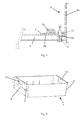
- Figures 1 and 2 show a mechanism 100 for sliding, in a substantially horizontal direction, a container 1 outwards and inwards in an inner chamber 2.
- the mechanism 100 comprises:
- the connecting piece 6 comprises a vertical first connecting member 6a to connect said piece 6 to the front door 3, a horizontal second connecting member 6b to connect said piece 6 to the guide 5 and a third connecting member 6c in the form of a hub to fix said piece 6 to the container 1.
- each guide 5 comprises a flange 7 on the top part of the end closest to the front door 3.
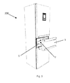
- Figure 3 shows said flange 7 in detail and a recess that comprises the horizontal second connecting member 6b of the connecting piece 6 where the flange 7 of the guide 5 is pre-fixed.
- the guide 5 is then fixed to the piece 6, binding said connecting piece 6 against the guide 5 by means of the plastic deformation of the connecting piece 6, as shown below.
- the connecting piece 6 comprises a through hole 11 and a threaded hole 12. Both holes are coaxial and are separated from each other by an intermediate space or gap in which one end of the guide 5 is housed.
- a connecting member preferably a screw (not shown in the figure) passes through the first hole 11 and self-traps into the second hole 12. The tightening of said screw causes a plastic deformation of the connecting piece 6, where the areas 6d and 6e tend to join together, binding in their interior the guide 5, which, logically, also comprises a hole (not shown in the figures) in the top part located close to the end closest to the front door 3 and which is coaxial to the holes 11 and 12.
- the second hole 12 is a threaded hole, thereby enabling the use of a cheaper standard screw.
- the container 1, which slides as a result of the mechanism 100 of the invention, comprises a longitudinal tongue 8 on each side of the container 1, as can be seen in Figures 2 and 4 .
- the container 1 is supported on the guides 5 by means of said tongues 8 and is centered and fixed to the mechanism 100, with the two housings 9, disposed on each end of each side, as shown in Figure 4 , being fitted on the hub of each third connecting member 6c of each connecting piece 6.
- This design enables the container 1 to be fixed on the mechanism 100 in a simple manner.
- the container 1 comprises handles 13 on the sides (see Figures 2 and 4 ) to allow the container 1 to be taken out comfortably.
- the connecting piece 6 enables a simple design for the guides 5.
- the guide 5 is in fact a tubular guide, preferably with an inverted U-shape that slides along the rails 4.
- manufacturing costs are reduced, as is the total weight of the structure of the mechanism 100 of the invention.
- the front door 3 comprises, for each connecting piece 6, on its inner side, a substantially flat support face 10 enabling each piece 6 to be connected to the front door 3.
- screws are preferably used for the connection.
- Other connections that do not use screws are possible, such as the first connecting member 6a of the piece 6 being fitted into a guide built into the front door 3.
- the connecting piece 6 is made of plastic, which helps reduce the total weight of the structure of the mechanism 100 of the invention.
- the container 1 exits or enters the inner chamber 2 when the front door 3 of, for example, a cooling appliance 200 is pulled or pushed, as shown in Figure 5 .
Landscapes
- Engineering & Computer Science (AREA)
- Chemical & Material Sciences (AREA)
- Combustion & Propulsion (AREA)
- Physics & Mathematics (AREA)
- Mechanical Engineering (AREA)
- Thermal Sciences (AREA)
- General Engineering & Computer Science (AREA)
- Refrigerator Housings (AREA)
- Devices That Are Associated With Refrigeration Equipment (AREA)
Applications Claiming Priority (1)
| Application Number | Priority Date | Filing Date | Title |
|---|---|---|---|
| ES200930019A ES2376105B1 (es) | 2009-03-31 | 2009-03-31 | Mecanismo para deslizar un contenedor, preferiblemente para un aparato frigorífico. |
Publications (1)
| Publication Number | Publication Date |
|---|---|
| EP2241845A2 true EP2241845A2 (de) | 2010-10-20 |
Family
ID=42307252
Family Applications (1)
| Application Number | Title | Priority Date | Filing Date |
|---|---|---|---|
| EP10382072A Withdrawn EP2241845A2 (de) | 2009-03-31 | 2010-03-30 | Mechanismus zur Schiebung eines Behälters, insbesondere für eine Kühlvorrichtung |
Country Status (2)
| Country | Link |
|---|---|
| EP (1) | EP2241845A2 (de) |
| ES (1) | ES2376105B1 (de) |
Cited By (3)
| Publication number | Priority date | Publication date | Assignee | Title |
|---|---|---|---|---|
| CN102128537A (zh) * | 2011-04-07 | 2011-07-20 | 合肥美的荣事达电冰箱有限公司 | 抽屉式冰箱的闭门装置和具有该闭门装置的冰箱 |
| CN103512307A (zh) * | 2012-06-28 | 2014-01-15 | 珠海格力电器股份有限公司 | 滑动安装结构以及包括该滑动安装结构的制冷设备 |
| CN107525340A (zh) * | 2017-08-31 | 2017-12-29 | 青岛海尔股份有限公司 | 一种用于冰箱抽屉的支架及具有其的冰箱 |
Citations (1)
| Publication number | Priority date | Publication date | Assignee | Title |
|---|---|---|---|---|
| JP2006343051A (ja) | 2005-06-09 | 2006-12-21 | Toshiba Corp | 冷蔵庫 |
Family Cites Families (3)
| Publication number | Priority date | Publication date | Assignee | Title |
|---|---|---|---|---|
| DE19510119B4 (de) * | 1995-03-21 | 2005-06-02 | MEPLA-WERKE LAUTENSCHLäGER GMBH & CO. KG | Schnellmontage-Befestigungsbeschlag für Schubladen-Frontblenden |
| DE102005021593A1 (de) * | 2005-05-10 | 2006-11-16 | BSH Bosch und Siemens Hausgeräte GmbH | Teleskopauszugsanordung |
| KR101356827B1 (ko) * | 2007-06-22 | 2014-01-29 | 엘지전자 주식회사 | 냉장고 및 냉장고 조립방법 |
-
2009
- 2009-03-31 ES ES200930019A patent/ES2376105B1/es not_active Expired - Fee Related
-
2010
- 2010-03-30 EP EP10382072A patent/EP2241845A2/de not_active Withdrawn
Patent Citations (1)
| Publication number | Priority date | Publication date | Assignee | Title |
|---|---|---|---|---|
| JP2006343051A (ja) | 2005-06-09 | 2006-12-21 | Toshiba Corp | 冷蔵庫 |
Cited By (7)
| Publication number | Priority date | Publication date | Assignee | Title |
|---|---|---|---|---|
| CN102128537A (zh) * | 2011-04-07 | 2011-07-20 | 合肥美的荣事达电冰箱有限公司 | 抽屉式冰箱的闭门装置和具有该闭门装置的冰箱 |
| CN102128537B (zh) * | 2011-04-07 | 2012-08-22 | 合肥美的荣事达电冰箱有限公司 | 抽屉式冰箱的闭门装置和具有该闭门装置的冰箱 |
| CN103512307A (zh) * | 2012-06-28 | 2014-01-15 | 珠海格力电器股份有限公司 | 滑动安装结构以及包括该滑动安装结构的制冷设备 |
| CN103512307B (zh) * | 2012-06-28 | 2015-07-15 | 珠海格力电器股份有限公司 | 滑动安装结构以及包括该滑动安装结构的制冷设备 |
| CN107525340A (zh) * | 2017-08-31 | 2017-12-29 | 青岛海尔股份有限公司 | 一种用于冰箱抽屉的支架及具有其的冰箱 |
| WO2019042348A1 (zh) * | 2017-08-31 | 2019-03-07 | 青岛海尔股份有限公司 | 一种用于冰箱抽屉的支架及具有其的冰箱抽屉 |
| CN107525340B (zh) * | 2017-08-31 | 2019-05-31 | 青岛海尔股份有限公司 | 一种用于冰箱抽屉的支架及具有其的冰箱 |
Also Published As
| Publication number | Publication date |
|---|---|
| ES2376105B1 (es) | 2013-02-05 |
| ES2376105A1 (es) | 2012-03-09 |
Similar Documents
| Publication | Publication Date | Title |
|---|---|---|
| CN111670322B (zh) | 可调整的吊架杆组合件 | |
| KR101728078B1 (ko) | 3도어 접철문의 슬라이드식 연동장치 | |
| AU2012252633B2 (en) | Drawer | |
| CN106132822B (zh) | 紧固件系统 | |
| US8511765B1 (en) | Two way travel drawer slide | |
| EP2241845A2 (de) | Mechanismus zur Schiebung eines Behälters, insbesondere für eine Kühlvorrichtung | |
| US9702615B1 (en) | Internal cabinet support structure | |
| CN112179034A (zh) | 冰箱 | |
| EP2983459A1 (de) | Schrank und schrankgruppe damit | |
| US20190082840A1 (en) | Cosmetic door panel suspension and adjustment system for a built-in appliance | |
| US20150360908A1 (en) | Column member for an elevating device | |
| CN106288620A (zh) | 左右开门机构及冰箱 | |
| US20150130194A1 (en) | Glove box for vehicle | |
| US20130278125A1 (en) | Drawer slides for face frame cabinets | |
| AU2015307547A1 (en) | Refrigerator door and refrigerator | |
| CN102980358B (zh) | 用于冰箱的门体组件及具有它的冰箱 | |
| US20150259962A1 (en) | Multifunction frame for an electric sliding door | |
| CN218164628U (zh) | 一种抽屉滑轨用调节机构及抽屉组件 | |
| JP6156457B2 (ja) | スライドシート用のワイヤハーネス配索装置 | |
| EP1715119B1 (de) | Einsteckgriff für Schiebeflügel oder dgl. | |
| CN202221206U (zh) | 冰箱抽屉的固定结构、设置固定结构的冰箱抽屉和冰箱 | |
| CN216416517U (zh) | 一种分隔组件的稳固装配结构 | |
| CN209472171U (zh) | 配电柜抽屉装置一次动静单级插接组件 | |
| EP2495516A2 (de) | Scharnier für eine Tür einer Kühlungsanwendung | |
| US20160261821A1 (en) | Television box |
Legal Events
| Date | Code | Title | Description |
|---|---|---|---|
| PUAI | Public reference made under article 153(3) epc to a published international application that has entered the european phase |
Free format text: ORIGINAL CODE: 0009012 |
|
| AK | Designated contracting states |
Kind code of ref document: A2 Designated state(s): AT BE BG CH CY CZ DE DK EE ES FI FR GB GR HR HU IE IS IT LI LT LU LV MC MK MT NL NO PL PT RO SE SI SK SM TR |
|
| AX | Request for extension of the european patent |
Extension state: AL BA ME RS |
|
| STAA | Information on the status of an ep patent application or granted ep patent |
Free format text: STATUS: THE APPLICATION IS DEEMED TO BE WITHDRAWN |
|
| 18D | Application deemed to be withdrawn |
Effective date: 20141001 |