EP2241858A2 - Navigationsvorrichtung und Navigationsverfahren - Google Patents
Navigationsvorrichtung und Navigationsverfahren Download PDFInfo
- Publication number
- EP2241858A2 EP2241858A2 EP10156518A EP10156518A EP2241858A2 EP 2241858 A2 EP2241858 A2 EP 2241858A2 EP 10156518 A EP10156518 A EP 10156518A EP 10156518 A EP10156518 A EP 10156518A EP 2241858 A2 EP2241858 A2 EP 2241858A2
- Authority
- EP
- European Patent Office
- Prior art keywords
- destination
- guidance
- route
- display
- display subject
- Prior art date
- Legal status (The legal status is an assumption and is not a legal conclusion. Google has not performed a legal analysis and makes no representation as to the accuracy of the status listed.)
- Granted
Links
Images





Classifications
-
- G—PHYSICS
- G01—MEASURING; TESTING
- G01C—MEASURING DISTANCES, LEVELS OR BEARINGS; SURVEYING; NAVIGATION; GYROSCOPIC INSTRUMENTS; PHOTOGRAMMETRY OR VIDEOGRAMMETRY
- G01C21/00—Navigation; Navigational instruments not provided for in groups G01C1/00 - G01C19/00
- G01C21/26—Navigation; Navigational instruments not provided for in groups G01C1/00 - G01C19/00 specially adapted for navigation in a road network
- G01C21/34—Route searching; Route guidance
- G01C21/36—Input/output arrangements for on-board computers
-
- G—PHYSICS
- G01—MEASURING; TESTING
- G01C—MEASURING DISTANCES, LEVELS OR BEARINGS; SURVEYING; NAVIGATION; GYROSCOPIC INSTRUMENTS; PHOTOGRAMMETRY OR VIDEOGRAMMETRY
- G01C21/00—Navigation; Navigational instruments not provided for in groups G01C1/00 - G01C19/00
- G01C21/26—Navigation; Navigational instruments not provided for in groups G01C1/00 - G01C19/00 specially adapted for navigation in a road network
- G01C21/34—Route searching; Route guidance
- G01C21/36—Input/output arrangements for on-board computers
- G01C21/3626—Details of the output of route guidance instructions
- G01C21/3635—Guidance using 3D or perspective road maps
-
- G—PHYSICS
- G01—MEASURING; TESTING
- G01C—MEASURING DISTANCES, LEVELS OR BEARINGS; SURVEYING; NAVIGATION; GYROSCOPIC INSTRUMENTS; PHOTOGRAMMETRY OR VIDEOGRAMMETRY
- G01C21/00—Navigation; Navigational instruments not provided for in groups G01C1/00 - G01C19/00
- G01C21/26—Navigation; Navigational instruments not provided for in groups G01C1/00 - G01C19/00 specially adapted for navigation in a road network
- G01C21/34—Route searching; Route guidance
- G01C21/36—Input/output arrangements for on-board computers
- G01C21/3626—Details of the output of route guidance instructions
- G01C21/3647—Guidance involving output of stored or live camera images or video streams
Definitions
- the present invention relates to navigation apparatuses and navigation methods, and, more particularly, to a navigation apparatus and a navigation method which are preferably applied to a vehicle navigation apparatus designed for vehicle use.
- Japanese Unexamined Patent Application Publication No. 11-65428 discloses a navigation apparatus for three-dimensionally displaying a target building on a map display screen.
- the navigation apparatus disclosed in Japanese Unexamined Patent Application Publication No. 11-65428 three-dimensionally displays only the target building. Accordingly, the relationship between the position of the target building and the current position of a user's vehicle is unclear. If a plurality of buildings are present near the target building, it is difficult for a user to determine whether a building in front of the user is the target building.
- the present invention provides a navigation apparatus and a navigation method which are capable of allowing a user to determine which of displayed subjects is a subject set as a destination on the basis of the relationship between the current position of the user and the destination with certainty.
- a navigation apparatus includes: positioning means for measuring a current position; route guidance screen generating means for generating a route guidance screen used for route guidance for a retrieved route from the current position to a destination and displaying the route guidance screen on displaying means; and guidance image generating means for, in a case where a remaining distance between the current position and the destination is a predetermined value or less while route guidance is performed using the route guidance screen, generating a guidance image in which a display subject representing the destination is highlighted such that the display subject is more prominently displayed than a vicinity of the display subject and displaying the guidance image on the displaying means.
- a navigation method includes the steps of: causing positioning means to measure a current position; causing route guidance screen generating means to generate a route guidance screen used for route guidance for a retrieved route from the current position to a destination and display the route guidance screen on displaying means; and causing guidance image generating means to, in a case where a remaining distance between the current position and the destination is a predetermined value or less while route guidance is performed using the route guidance screen, generate a guidance image in which a display subject representing the destination is highlighted such that the display subject is more prominently displayed than a vicinity of the display subject and display the guidance image on the displaying means.
- a guidance image is displayed in which a display subject representing the destination is highlighted such that the display subject is more prominently displayed than a vicinity of the display subject.
- a guidance image is displayed in which a display subject representing the destination is highlighted such that the display subject is more prominently displayed than a vicinity of the display subject.
- Embodiments of the present invention will be described in the order of 1. First Embodiment, 2. Second Embodiment, and 3. Other Embodiments.
- Fig. 1 is a diagram illustrating a Personal Navigation Device (PND) 2 according to the first embodiment of the present invention.
- a cradle 5 disposed on the back surface of the PND 2 is attached to a vehicle's dashboard with a suction cup 5A and is electrically connected to a vehicle's battery.
- the PND 2 is attached/removed to/from a vehicle with the cradle 5.
- the PND 2 is held by the cradle 5 and is mechanically and electrically connected to the cradle 5.
- the PND 2 operates with power supplied from the vehicle's battery via the cradle 5.
- the PND 2 operates with power supplied from an internal battery.
- a display unit 14 is disposed on the front surface of the PND 2.
- the PND 2 displays on the display unit 14 a map image or the like generated from map data stored in a storage unit (not illustrated) included therein.
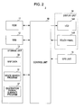
- the PND 2 includes a control unit 10 having a configuration of a Central Processing Unit (CPU).
- the control unit 10 decompresses a basic program stored in a Read-Only Memory (ROM) 11 into a Random Access Memory (RAM) 12, and performs overall control in accordance with the basic program.
- ROM Read-Only Memory
- RAM Random Access Memory
- the control unit 10 included in the PND 2 decompresses various application programs such as a route search program 31 and a destination arrival guidance program 32 stored in the storage unit 13 into the RAM 12 and performs various processing operations including navigation processing in accordance with these application programs.
- the PND 2 includes a Global Positioning System (GPS) unit 15.
- GPS Global Positioning System
- the GPS unit 15 accurately measures the current position of a vehicle on the basis of orbital data obtained by receiving satellite signals from a plurality of GPS satellites and demodulating these satellite signals and data of a distance between each of these GPS satellites and the vehicle, thereby obtaining GPS information including current position information represented by a latitude and a longitude and time information included in the satellite signals.
- the GPS unit 15 supplies the GPS information to the control unit 10.
- Map data 30 is stored in the storage unit 13.
- various application programs such as the route search program 31 and the destination arrival guidance program 32 are installed in the storage unit 13 in advance.
- the map data 30 includes road data for display, road data for route search, pieces of building data concerning positions of various facilities and various buildings, etc. Each of these pieces of data is represented by a set of coordinates (represented by a latitude and a longitude) of nodes and links between nodes.
- the control unit 10 reads vicinity map data including data of the current position of a vehicle from the map data 30 stored in the storage unit 13 into the RAM 12 on the basis of the GPS information. Subsequently, the control unit 10 generates a map image including the current position of the vehicle on the basis of the read vicinity map data and displays the map image on a Liquid Crystal Display (LCD) 14A included in the display unit 14.
- LCD Liquid Crystal Display
- a touch panel 14B for receiving a touch operation performed by a user is disposed on the surface of the display unit 14.
- the control unit 10 searches for a route from the current position to the destination in accordance with the route search program 31 stored in the storage unit 13, generates retrieved route information, and stores the retrieved route information in the RAM 12.
- the route search program 31 is able to allow a user to set not only a destination but also a way point on a route to a destination and various conditions for the reduction in a travel distance, the reduction in a travel time, and the reduction in payment of a toll for using a road.
- the retrieved route information is represented by data of a sequence of all nodes on the route from a starting point to a destination retrieved by the control unit 10.
- the control unit 10 outputs to the LCD 14A a route guidance screen (to be described later) on which the retrieved route is displayed with a color different from that of other roads or a line of a width larger than a line width of other roads so as to cause the LCD 14A to display the route guidance screen.
- a route guidance screen (to be described later) on which the retrieved route is displayed with a color different from that of other roads or a line of a width larger than a line width of other roads so as to cause the LCD 14A to display the route guidance screen.
- control unit 10 not only causes the LCD 14A to display the route guidance screen on which the retrieved route is displayed but also generates sound information used to guide or support driving by a user (used for route guidance) while a vehicle travels to a destination by the retrieved route.
- the control unit 10 causes a speaker (not illustrated) to output the sound information as navigation sound at the time of route guidance.
- the PND 2 can provide a navigation function of navigating a vehicle to a destination desired by a user.
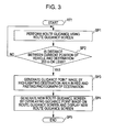
- the control unit 10 included in the PND 2 decompresses the destination arrival guidance program 32 stored in the storage unit 13 into the RAM 12 and performs a destination arrival guidance process (to be described later), thereby guiding a user to a destination with certainty without confusing the user.
- step SP1 the control unit 10 included in the PND 2 performs route guidance using a route guidance screen on which a route from a current position to a destination retrieved in accordance with the route search program 31 is displayed. Subsequently, the process proceeds to step SP2.
- the control unit 10 displays a flag mark DE1 indicating a destination and a vehicle mark NP1 indicating the current position of a user's own vehicle on a route guidance screen MG1 displayed on the display unit 14 on a predetermined scale.
- the vehicle mark NP1 is displayed such that it is on the retrieved route on the near side of the flag mark DE1.
- control unit 10 performs route guidance by allowing a user to visually check the vehicle mark NP1 traveling to a destination represented by the flag mark DE1 on the route guidance screen MG1.
- step SP2 the control unit 10 determines whether a remaining distance between the current position of the vehicle and the destination is, for example, 200 m or less. In a case where a negative result is obtained in step SP2, it is determined that the distance between the current position of the vehicle and the destination is 200 m or more and the current position of the vehicle is far from the destination. At that time, the process returns to step SP1.
- step SP2 if a positive result is obtained in step SP2, it is determined that the remaining distance between the current position of the vehicle and the destination is 200 m or less and the vehicle will arrive at the destination soon. At that time, the process proceeds to step SP3.
- step SP3 the control unit 10 highlights in red a destination area AR1 (that is diagonally shaded) in which the destination represented by the flag mark DE1 is located as illustrated in Fig. 4B , and pastes an external photograph PT1 of, for example, a destination building next to the destination area AR1, thereby generating a guidance point image GP1. Subsequently, the process proceeds to step SP4.
- the guidance point image GP1 is displayed on a scale larger than that used for display of the route guidance screen MG1.
- the guidance point image GP1 not only the destination area AR1 in which the destination represented by the flag mark DE1 is located but also the vicinity of the destination area AR1 are displayed in detail, and the vehicle mark NP1 is also displayed. Accordingly, a user can intuitively recognize the positional relationship between the flag mark DE1 and the vehicle mark NP1 using the guidance point image GP1.
- the external photograph PT1 of the destination building is displayed near the destination area AR1 in which the flag mark DE1 is located in the guidance point image GP1, a user can visually check which of a plurality of buildings is the destination building with certainty.
- step SP4 the control unit 10 generates a new route guidance screen MG2 by overlaying the guidance point image GP1 generated in step SP3 on the route guidance screen MG1 (see, Fig. 4A ) and displays the route guidance screen MG2 on the display unit 14. Subsequently, the process proceeds to step SP5 in which the process ends.
- the control unit 10 displays the route guidance screen MG2 obtained by overlaying the guidance point image GP1 on the route guidance screen MG1.
- control unit 10 allows a user to easily recognize the positional relationship between the vehicle mark NP1 and the destination area AR1 highlighted in red using the guidance point image GP1, the control unit 10 allows the user to roughly grasp the distance between the current position of the vehicle and the destination and to intuitively understand which of buildings is the destination.
- control unit 10 allows a user to compare the external appearance of an actual destination building and the external appearance of a building displayed in the external photograph PT1 of the destination pasted next to the destination area AR1 using the guidance point image GP1, the control unit 10 can guide the user to the destination building with certainty without allowing the user to mistake the destination building for another building.
- control unit 10 allows a user to recognize the positional relationship between the vehicle mark NP1 and the destination area AR1 highlighted in red using the guidance point image GP1 and to accurately understand a destination building using the external photograph PT1 of the destination pasted next to the destination area AR1, the control unit 10 can guide the user to the destination building with certainty.
- Fig. 5 is a diagram illustrating a navigation system 1 according to the second embodiment of the present invention.
- the navigation system 1 includes a PND 20 having a basic configuration similar to that of the PND 2 according to the first embodiment, a plurality of wireless access points 3a, 3b, 3c, ⁇ , and a server 4.
- the PND 20 When the PND 20 is wirelessly connected to one of the wireless access points 3a, 3b, 3c, ⁇ , the PND 20 is connected to the server 4 via the wireless access point and the Internet NT.
- the cradle 5 disposed on the back surface of the PND 20 is attached to a vehicle's dashboard with the suction cup 5A and is electrically connected to a vehicle's battery.
- the PND 20 is attached/removed to/from a vehicle with the cradle 5.
- the PND 20 is held by the cradle 5 and is mechanically and electrically connected to the cradle 5.
- the PND 20 operates with power supplied from the vehicle's battery via the cradle 5.
- the PND 20 operates with power supplied from an internal battery.
- the display unit 14 is disposed on the front surface of the PND 20.
- the PND 20 displays on the display unit 14 a map image or the like generated from map data stored in a storage unit (not illustrated) included therein.
- the PND 20 has a basic configuration similar to that of the PND 2 according to the first embodiment except for a wireless communication unit 16.
- the control unit 10 included in the PND 20 decompresses a basic program stored in the ROM 11 into the RAM 12 and performs overall control processing. Furthermore, the control unit 10 decompresses various application programs stored in the storage unit 13 into the RAM 12 and performs various processing operations including navigation processing.
- the GPS unit 15 included in the PND 20 accurately measures the current position of a vehicle on the basis of orbital data obtained by receiving satellite signals from a plurality of GPS satellites and demodulating these satellite signals and data of a distance between each of these GPS satellites and the vehicle, thereby obtaining GPS information including current position information and time information.
- the GPS unit 15 supplies the GPS information to the control unit 10.
- the control unit 10 reads vicinity map data including data of the current position of a vehicle from the map data 30 stored in the storage unit 13 into the RAM 12 on the basis of the GPS information. Subsequently, the control unit 10 generates a map image including the current position of the vehicle on the basis of the read vicinity map data and displays the map image on the LCD 14A included in the display unit 14.
- control unit 10 searches for a route from the current position to the destination in accordance with the route search program 31 stored in the storage unit 13, generates retrieved route information, and stores the retrieved route information in the RAM 12.
- the control unit 10 outputs to the LCD 14A the route guidance screen MG1 (see, Fig. 4A ) on which the retrieved route is displayed with a color different from that of other roads or a line of a width larger than a line width of other roads so as to cause the LCD 14A to display the route guidance screen MG1.
- control unit 10 not only causes the LCD 14A to display the route guidance screen MG1 on which the retrieved route is displayed but also causes a speaker (not illustrated) to output sound information used to guide or support driving by a user (used for route guidance) as navigation sound while a vehicle travels to a destination by the retrieved route.
- the PND 20 can also provide a navigation function of navigating a vehicle to a destination desired by a user.
- the PND 20 includes the wireless communication unit 16 including, for example, a WI-FI (registered trademark) module.
- the PND 20 retrieves the wireless access points 3a to 3c (see, Fig. 5 ) with which the wireless communication unit 16 can wirelessly communicate.
- the wireless communication unit 16 When the PND 20 retrieves the wireless access points 3a to 3c with which the wireless communication unit 16 can wirelessly communicate, the wireless communication unit 16 is wirelessly connected to the server 4 via the retrieved wireless access points 3a to 3c and the Internet NT.
- the control unit 10 included in the PND 20 decompresses a destination arrival guidance program 37 stored in the storage unit 13 into the RAM 12 and performs a destination arrival guidance process (to be described later), thereby guiding a user to a destination with certainty without confusing the user.
- the server 4 includes a control unit 40 having a CPU configuration.
- the control unit 40 decompresses a basic program stored in a ROM 41 into a RAM 42 and performs overall control in accordance with the basic program.
- the control unit 40 included in the server 4 decompresses various application programs stored in the storage unit 43 into the RAM 42 and generates in accordance with these application programs a three-dimensional guidance point image (to be described later) used to support a destination arrival guidance process performed by the PND 20.
- a storage unit 43 stores an image generation program 45 used to generate a three-dimensional guidance point image and a building drawing information database 46.
- the control unit 40 communicates with the PND 20 via a network interface 44 so as to transmit to the PND 20, for example, a three-dimensional guidance point image.
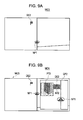
- the control unit 10 included in the PND 20 generates a route guidance screen MG3 illustrated in Fig. 9A in accordance with the route search program 31 and performs route guidance for a route from a current position to a destination using the route guidance screen MG3 in step SP11. Subsequently, the process proceeds to step SP12.
- the control unit 10 included in the PND 20 displays a flag mark DE2 indicating a destination and the vehicle mark NP1 indicating the current position of a vehicle on the route guidance screen MG3 (see, Fig. 9A ) displayed on the display unit 14.
- the vehicle mark NP1 is displayed such that it is on a retrieved route on the near side of the flag mark DE2.
- control unit 10 included in the PND 20 performs route guidance while allowing a user to visually check the vehicle mark NP1 traveling to a destination represented by the flag mark DE2 on the route guidance screen MG3.
- step SP12 the control unit 10 included in the PND 20 determines whether a remaining distance between the current position of the vehicle and the destination is, for example, 2 km or less. In a case where a negative result is obtained in step SP12, it is determines that the distance between the current position of the vehicle and the destination is 2 km or more and the current position of the vehicle is far from the destination. At that time, the process returns to step SP11.
- step SP12 determines that the distance between the current position of the vehicle and the destination is 2 km or less and the current position of the vehicle is near the destination. At that time, the process proceeds to step SP13.
- step SP13 the control unit 10 included in the PND 20 wirelessly transmits from the wireless communication unit 16 to the server 4 destination information about a destination for which route guidance is being performed using the route guidance screen MG3 and route information indicating a retrieved route from a starting point to the destination. At that time, the process proceeds to step SP14.
- step SP21 the control unit 40 included in the server 4 recognizes the address, name, latitude and longitude, and telephone number of the destination on the basis of the destination information received from the PND 20 and specifies a specific building located at the destination on the basis of a result of the recognition. Subsequently, the process proceeds to step SP22.
- step SP22 the control unit 40 included in the server 4 determines whether the building drawing information database 46 stores image information about the shape or texture of the building specified in step SP22 which is used to express a three-dimensional shape.
- step SP22 If a negative result is obtained in step SP22, it is determined that the image information used to three-dimensionally display a building is not stored in the building drawing information database 46. Subsequently the process proceeds to step SP23.
- step SP23 the control unit 40 included in the server 4 highlights in red a destination area AR2 in which the destination represented by the flag mark DE2 is located as illustrated in Fig. 9B , and pastes an external photograph PT2 of, for example, a destination building next to the destination area AR2, thereby generating a guidance point image GP2. Subsequently, the process proceeds to step SP24.
- the guidance point image GP2 (see, Fig. 9B ) is displayed on a scale larger than that used for display of the route guidance screen MG3 (see, Fig. 9A ).
- the guidance point image GP2 not only the destination area AR2 in which the destination represented by the flag mark DE2 is located but also the vicinity of the destination area AR2 are displayed in detail, and the vehicle mark NP1 is also displayed.
- the navigation system 1 allows a user to intuitively recognize the positional relationship between the flag mark DE2 and the vehicle mark NP1 using the guidance point image GP2.
- the external photograph PT2 of the destination building is displayed near the destination area AR2 in which the flag mark DE2 is located in the guidance point image GP2, a user can visually check which of a plurality of buildings is the destination building with certainty.
- step SP24 the control unit 40 included in the server 4 wirelessly transmits the guidance point image GP2 generated in step SP23 to the PND 20 via the network interface 44. Subsequently, the process proceeds to step SP29 in which the process ends.
- step SP22 if a positive result is obtained in step SP22, it is determined that the image information used to three-dimensionally display a building is stored in the building drawing information database 46. At that time, the process proceeds to step SP25.
- step SP25 the control unit 40 included in the server 4 refers to a guidance point used when the PND 20 causes a speaker to output navigation sound on the basis of the route information received from the PND 20. Subsequently, the process proceeds to step SP26.
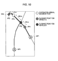
- the control unit 10 included in the PND 20 sets, for example, a position 400 m before the destination area AR2 in which the destination building is located as a guidance point at which, for example, navigation sound "You are 400 m before the destination" is output.
- control unit 10 sets a position 400 m before the destination area AR2 as a guidance point PP1 for a vehicle A traveling along a road.
- the guidance point PP1 is used as a position functioning as a trigger for display of a guidance point image (to be described later) which is performed by the control unit 10 included in the PND 20 immediately after the vehicle A has passed through the guidance point PP1.
- the control unit 10 included in the PND 20 sets the right-turning or left-turning intersection as a guidance point PP2 at which, for example, navigation sound "You are 250 m before the destination" is output from a speaker.
- the guidance point PP2 is also used as a position functioning as a trigger for display of a guidance point image (to be described later) which is performed by the control unit 10 included in the PND 20 immediately after the vehicle B has passed through the guidance point PP2.
- the control unit 10 included in the PND 20 sets a usual guidance point before the guidance point PP2 as the guidance point for the vehicle B since it is too late to display a guidance point image (to be described later) immediately after the vehicle B has passed through the guidance point PP2.
- step SP26 the control unit 40 included in the server 4 generates a three-dimensional guidance point image (to be described later) to be displayed by the PND 20 immediately after a vehicle has passed through the guidance point PP1 or PP2. Subsequently, the process proceeds to step SP27.
- the control unit 40 included in the server 4 estimates an angle at which a user views the destination building at a position 100 m before the destination area AR2.
- the control unit 40 included in the server 4 generates a guidance point image GP3 illustrated in Fig. 11B on the basis of the image information stored in the building drawing information database 46 included in the storage unit 43.
- a building image is highlighted such that a three-dimensional appearance is applied to buildings when the buildings are viewed at the estimated angle.
- step SP27 the control unit 40 included in the server 4 assumes that the PND 20 sets, for example, a position 5 m before the destination area AR2 as a destination arrival guidance point PP3 as illustrated in Fig. 10 , and generates a building image to be displayed at the time of arrival (to be described later) in accordance with the image generation program 45. Subsequently, the process proceeds to step SP28.
- the control unit 40 included in the server 4 estimates that an angle at which a user views the destination building from a position 5 m before the destination area AR2 in which the destination building is located is approximately 45° as illustrated in Fig. 12A .
- the control unit 40 included in the server 4 generates a building image GG to be displayed at the time of arrival (hereinafter referred to as an arrival display building image GG) illustrated in Fig. 12B on the basis of the image information stored in the building drawing information database 46 included in the storage unit 43.
- an arrival display building image GG a building image is highlighted such that a three-dimensional appearance is applied to buildings when the buildings are viewed at the estimated angle.
- the control unit 40 included in the server 4 If another building overlapping the destination is present, the control unit 40 included in the server 4 generates the arrival display building image GG that is a three-dimensional building image of only the destination as if the building overlapping the destination were not present.
- step S28 the control unit 40 included in the server 4 wirelessly transmits the guidance point image GP3 generated in step SP26 and the arrival display building image GG generated in step SP27 to the PND 20 via the network interface 44. Subsequently, the process proceeds to step SP29 in which the process ends.
- the control unit 10 If the guidance point image GP2 is transmitted from the server 4 to the control unit 10 included in the PND 20 in step SP24, the control unit 10 generates a new route guidance screen MG4 by overlaying the guidance point image GP2 on the route guidance screen MG3 and displays the route guidance screen MG4 on the display unit 14 immediately after the vehicle mark NP1 has passed through the guidance point PP1 or PP2 in step SP14. Subsequently, the process proceeds to step SP15.
- the control unit 10 If the guidance point image GP3 and the arrival display building image GG are transmitted from the server 4 to the control unit 10 included in the PND 20 in step SP28, the control unit 10 generates a new route guidance screen MG5 by overlaying the guidance point image GP3 on the route guidance screen MG3 as illustrated in Fig. 13 and displays the route guidance screen MG5 on the display unit 14 immediately after the vehicle mark NP1 has passed through the guidance point PP1 or PP2 in step SP14. Subsequently, the process proceeds to step SP15.
- step SP15 when the vehicle mark NP1 arrives at the destination arrival guidance point PP3 5 m before the destination area AR2, the control unit 10 included in the PND 20 generates a new route guidance screen MG6 by overlaying the arrival display building image GG on the route guidance screen MG3 as illustrated in Fig. 14 and displays the route guidance screen MG6 on the display unit 14. Subsequently, the process proceeds to step SP16 in which the process ends.
- the PND 20 included in the navigation system 1 performs route guidance using the route guidance screen MG3, the PND 20 transmits destination information and route information to the server 4.
- the server 4 specifies a building located at the destination represented by the flag mark DE2 on the basis of the destination information transmitted from the PND 20. If image information used to three-dimensionally display the building is stored in the building drawing information database 46, the server 4 generates the guidance point image GP3 to be displayed by the PND 20 immediately after a vehicle has passed through the guidance point PP1 or PP2.
- the server 4 generates the arrival display building image GG to be viewed by a user at the time of arrival at the destination arrival guidance point PP3 that is, for example, 5 m before the destination area AR2 on the basis of the image information stored in the building drawing information database 46.
- the server 4 transmits the guidance point image GP3 and the arrival display building image GG to the PND 20 so as to cause the PND 20 to display the route guidance screen MG5 on which the guidance point image GP3 is pasted immediately after a vehicle has passed through the guidance point PP1 or PP2 and then to display the route guidance screen MG6 on which the arrival display building image GG is pasted at the destination arrival guidance point PP3 5 m before the destination area AR2.
- the PND 20 allows a user to visually check the three-dimensional image of a destination building to be actually viewed by the user using the guidance point image GP3 immediately after the user's vehicle has passed through the guidance point PP1 or PP2 that is 400 m or less before the destination area AR2, the PND 20 can prevent the user from passing through the destination building.
- the PND 20 allows a user to visually check the arrival display building image GG that is the same as the external appearance of a destination building to be viewed by the user at the time of arrival at the guidance point PP3, the PND 20 can guide the user to the destination building with certainty.
- the PND 20 can receive from the server 4 the guidance point image GP3 and the arrival display building image GG only by transmitting destination information and route information to the server 4, it is not necessary for the PND 20 to store the image generation program 45 and the building drawing information database 46. Accordingly, the configuration of the PND 20 can be simplified.
- the PND 20 expresses the external appearance of a destination building to be viewed by a user using the guidance point image GP3 after a vehicle has passed through the guidance point PP1 or PP2 and using the arrival display building image GG at the time of arrival at the destination arrival guidance point PP3, and allows the user to visually check the guidance point image GP3 and the arrival display building image GG.
- the PND 20 can guide the user to the destination building with certainty.
- control unit 10 included in the PND 2 generates the route guidance screen MG2 by overlaying the guidance point image GP1 on the route guidance screen MG1.
- control unit 10 included in the PND 2 may display only the guidance point image GP1 instead of the route guidance screen MG1.
- control unit 10 included in the PND 20 generates the route guidance screen MG5 by overlaying the guidance point image GP3 on the route guidance screen MG3.
- control unit 10 included in the PND 20 may display only the guidance point image GP3 instead of the route guidance screen MG3.
- control unit 10 included in the PND 20 generates the route guidance screen MG6 by overlaying the arrival display building image GG on the route guidance screen MG3.
- control unit 10 included in the PND 20 may display only the arrival display building image GG instead of the route guidance screen MG3.
- control unit 10 included in the PND 2 highlights only the destination area AR1 in red.
- control unit 10 included in the PND 2 may display, for example, an area at an intersection on the near side of the area AR1 in another color so as to remind a user to turn to the right/left.
- the PND 20 receives the guidance point image GP2 and the arrival display building image GG generated by the server 4 and displays them.
- the control unit 10 included in the PND 20 may have the image generation program 45 and the building drawing information database 46, generate the guidance point image GP2 and the arrival display building image GG, and display them.
- the image of a building is highlighted such that a three-dimensional appearance is applied to the building.
- the control unit 10 included in the PND 20 may highlight the three-dimensional image of the building in red in accordance with the image generation program 45 and the building drawing information database 46.
- the control unit 10 included in the PND 2 performs the destination arrival guidance process (see, Fig. 3 ) of the routine RT1 in accordance with the destination arrival guidance program 32.
- the control unit 10 included in the PND 2 may perform the destination arrival guidance process of the routine RT1 in accordance with the destination arrival guidance program 32 that is installed from a predetermined recording medium, is downloaded from the Internet, or is installed by another route.
- control unit 10 included in the PND 20 performs the process from step SP11 to step SP16 (see, Fig. 8 ) in accordance with the destination arrival guidance program 37.
- control unit 10 included in the PND 20 may perform the process from step SP11 to step SP16 in accordance with the destination arrival guidance program 37 that is installed from a predetermined recording medium, is downloaded from the Internet, or is installed by another route.
- control unit 40 included in the server 4 performs the process from step SP21 to step SP29 (see, Fig. 8 ) in accordance with the image generation program 45.
- control unit 40 included in the server 4 may perform the process from step SP21 to step SP29 in accordance with the image generation program 45 that is installed from a predetermined recording medium, is downloaded from the Internet, or is installed by another route.
- a navigation apparatus includes the GPS unit 15 corresponding to positioning means, the control unit10 corresponding to route guidance screen generating means, and the control unit 40 corresponding to guidance image generating means.
- a navigation apparatus may include positioning means, route guidance screen generating means, and guidance image generating means each of which has another configuration.
Landscapes
- Engineering & Computer Science (AREA)
- Radar, Positioning & Navigation (AREA)
- Remote Sensing (AREA)
- Automation & Control Theory (AREA)
- Physics & Mathematics (AREA)
- General Physics & Mathematics (AREA)
- Multimedia (AREA)
- Navigation (AREA)
- Instructional Devices (AREA)
Applications Claiming Priority (1)
| Application Number | Priority Date | Filing Date | Title |
|---|---|---|---|
| JP2009079615A JP2010230551A (ja) | 2009-03-27 | 2009-03-27 | ナビゲーション装置及びナビゲーション方法 |
Publications (3)
| Publication Number | Publication Date |
|---|---|
| EP2241858A2 true EP2241858A2 (de) | 2010-10-20 |
| EP2241858A3 EP2241858A3 (de) | 2010-12-01 |
| EP2241858B1 EP2241858B1 (de) | 2020-05-06 |
Family
ID=42712573
Family Applications (1)
| Application Number | Title | Priority Date | Filing Date |
|---|---|---|---|
| EP10156518.2A Not-in-force EP2241858B1 (de) | 2009-03-27 | 2010-03-15 | Navigationsvorrichtung und Navigationsverfahren |
Country Status (5)
| Country | Link |
|---|---|
| US (2) | US8898006B2 (de) |
| EP (1) | EP2241858B1 (de) |
| JP (1) | JP2010230551A (de) |
| CN (1) | CN101846527B (de) |
| TW (1) | TWI410607B (de) |
Cited By (3)
| Publication number | Priority date | Publication date | Assignee | Title |
|---|---|---|---|---|
| CN103458066A (zh) * | 2013-09-17 | 2013-12-18 | 百度在线网络技术(北京)有限公司 | 通过终端进行寻址的方法、系统和服务器 |
| EP3669143A4 (de) * | 2017-09-07 | 2021-05-26 | Uber Technologies, Inc. | Ansicht aus der ich-perspektive |
| US11308322B2 (en) | 2019-01-23 | 2022-04-19 | Uber Technologies, Inc. | Locating a client device using ground truth image rendering |
Families Citing this family (44)
| Publication number | Priority date | Publication date | Assignee | Title |
|---|---|---|---|---|
| US9691281B2 (en) * | 2010-03-24 | 2017-06-27 | Telenav, Inc. | Navigation system with image assisted navigation mechanism and method of operation thereof |
| CN102135433B (zh) * | 2010-12-09 | 2013-05-08 | 深圳市凯立德欣软件技术有限公司 | 精确导航方法及位置服务设备 |
| USD659568S1 (en) * | 2011-07-06 | 2012-05-15 | Garmin Switzerland Gmbh | Navigation device |
| USD659567S1 (en) * | 2011-07-06 | 2012-05-15 | Garmin Switzerland Gmbh | Navigation device |
| CN102519478B (zh) * | 2011-11-16 | 2016-01-13 | 深圳市凯立德科技股份有限公司 | 一种街景目的地引导方法及装置 |
| US8775068B2 (en) | 2012-05-29 | 2014-07-08 | Apple Inc. | System and method for navigation guidance with destination-biased route display |
| TWI450227B (zh) | 2012-06-05 | 2014-08-21 | Wistron Corp | 以不同光線效果且以軟體方式控制顯示提示訊息之導航裝置與導航方法 |
| USD750110S1 (en) * | 2012-11-08 | 2016-02-23 | Uber Technologies, Inc. | Display screen of a computing device with a computer-generated electronic panel for providing information of a service |
| WO2014097347A1 (ja) * | 2012-12-18 | 2014-06-26 | 三菱電機株式会社 | 視認性推定装置、視認性推定方法、及び安全運転支援システム |
| USD693706S1 (en) | 2013-01-02 | 2013-11-19 | Garmin Switzerland Gmbh | Navigation device |
| USD708078S1 (en) | 2013-01-02 | 2014-07-01 | Garmin Switzerland Gmbh | Navigation device |
| USD693705S1 (en) | 2013-01-02 | 2013-11-19 | Garmin Switzerland Gmbh | Navigation device |
| USD702571S1 (en) | 2013-01-02 | 2014-04-15 | Garmin Switzerland Gmbh | Navigation device |
| USD693707S1 (en) | 2013-01-02 | 2013-11-19 | Garmin Switzerland Gmbh | Navigation device |
| USD702140S1 (en) | 2013-01-02 | 2014-04-08 | Garmin Switzerland Gmbh | Navigation device |
| JP6236954B2 (ja) * | 2013-07-23 | 2017-11-29 | アイシン・エィ・ダブリュ株式会社 | 運転支援システム、方法およびプログラム |
| KR20150034997A (ko) * | 2013-09-27 | 2015-04-06 | 네이버 주식회사 | 경로 안내에 따른 목적지를 명확히 인지시켜 주기 위한 방법 및 그 시스템 |
| GB201318049D0 (en) * | 2013-10-11 | 2013-11-27 | Tomtom Int Bv | Apparatus and methods of displaying navigation instructions |
| USD724451S1 (en) | 2013-11-21 | 2015-03-17 | Garmin Switzerland Gmbh | Navigation device |
| USD719858S1 (en) | 2013-11-21 | 2014-12-23 | Garmin Switzerland Gmbh | Navigation device |
| USD727182S1 (en) | 2014-05-23 | 2015-04-21 | Garmin Switzerland Gmbh | Navigation device |
| CN104596523B (zh) * | 2014-06-05 | 2019-05-07 | 腾讯科技(深圳)有限公司 | 一种街景目的地引导方法和设备 |
| US9874456B2 (en) * | 2014-11-28 | 2018-01-23 | Here Global B.V. | Method, apparatus and computer program product for providing a destination preview |
| USD751933S1 (en) | 2014-12-22 | 2016-03-22 | Garmin Switzerland Gmbh | Navigation device |
| USD795268S1 (en) | 2015-02-27 | 2017-08-22 | Uber Technologies, Inc. | Display screen computing device with graphical user interface |
| USD775636S1 (en) | 2015-02-27 | 2017-01-03 | Uber Technologies, Inc. | Display screen for a computing device with graphical user interface |
| KR102411171B1 (ko) * | 2015-05-19 | 2022-06-21 | 엘지이노텍 주식회사 | 디스플레이장치 및 이의 동작 방법 |
| JP2017067527A (ja) * | 2015-09-29 | 2017-04-06 | アイシン・エィ・ダブリュ株式会社 | 経路案内システム、経路案内方法及びコンピュータプログラム |
| CN105222792A (zh) * | 2015-10-20 | 2016-01-06 | 魅族科技(中国)有限公司 | 导航方法、导航装置及移动终端 |
| JP1553720S (de) * | 2015-10-28 | 2016-07-11 | ||
| KR102482595B1 (ko) * | 2015-12-17 | 2022-12-30 | 삼성전자주식회사 | 지도 정보 제공 방법 및 이를 지원하는 전자 장치 |
| USD818040S1 (en) * | 2016-02-11 | 2018-05-15 | Dover Europe Sàrl | Display device for a printing machine |
| JP6342089B2 (ja) * | 2016-03-24 | 2018-06-13 | 三菱電機株式会社 | 支援画像表示装置、支援画像表示方法及び支援画像表示プログラム |
| CN106989757A (zh) * | 2017-04-01 | 2017-07-28 | 福建中金在线信息科技有限公司 | 一种导航定位方法和装置 |
| CN107622241A (zh) * | 2017-09-21 | 2018-01-23 | 百度在线网络技术(北京)有限公司 | 用于移动设备的显示方法和装置 |
| US11193784B2 (en) | 2017-10-13 | 2021-12-07 | Waymo Llc | End of trip sequence |
| CN108592939A (zh) * | 2018-07-11 | 2018-09-28 | 维沃移动通信有限公司 | 一种导航方法及终端 |
| CN110501007B (zh) * | 2019-09-06 | 2021-07-16 | 腾讯科技(深圳)有限公司 | 一种路径规划方法、装置及终端 |
| WO2021125706A1 (ko) * | 2019-12-18 | 2021-06-24 | 엘지전자 주식회사 | 차량 제어 장치 및 그것의 제어 방법 |
| US20220099454A1 (en) * | 2020-09-29 | 2022-03-31 | International Business Machines Corporation | Navigation street view tool |
| CN114323056A (zh) * | 2020-09-30 | 2022-04-12 | 比亚迪股份有限公司 | 一种驾驶导航方法,装置及汽车 |
| US20230152102A1 (en) * | 2021-11-15 | 2023-05-18 | Johnson Controls Tyco IP Holdings LLP | Building management system with indoor navigation features |
| USD1026685S1 (en) * | 2021-11-24 | 2024-05-14 | Navico, Inc. | Marine electronics display device |
| US20240192013A1 (en) * | 2022-12-07 | 2024-06-13 | Got Spot? | Distributed computing parking assist system |
Family Cites Families (31)
| Publication number | Priority date | Publication date | Assignee | Title |
|---|---|---|---|---|
| JPH0518381A (ja) | 1991-07-10 | 1993-01-26 | Ebara Corp | スクリユー形真空ポンプ |
| JP3767866B2 (ja) * | 1995-04-26 | 2006-04-19 | 本田技研工業株式会社 | 車両の情報表示装置 |
| KR100235239B1 (ko) * | 1995-09-29 | 1999-12-15 | 모리 하루오 | 가형정보의 출력장치, 가형정보의 출력방법, 지도표시장치, 지도표시방법, 네비게이션장치 및 네비게이션방법 |
| JP3836906B2 (ja) * | 1996-05-29 | 2006-10-25 | 富士通テン株式会社 | 経路案内装置 |
| JP3547947B2 (ja) * | 1997-08-11 | 2004-07-28 | アルパイン株式会社 | ナビゲーション装置における所在階数表示方法 |
| US6295066B1 (en) * | 1997-09-12 | 2001-09-25 | Hitachi, Ltd. | Method for generating virtual three-dimensional space |
| JP3902872B2 (ja) | 1997-09-12 | 2007-04-11 | 株式会社日立製作所 | 仮想3次元空間の生成プログラムを記録したコンピュータ読み取り可能な記録媒体、及び仮想3次元空間生成装置 |
| US6182010B1 (en) * | 1999-01-28 | 2001-01-30 | International Business Machines Corporation | Method and apparatus for displaying real-time visual information on an automobile pervasive computing client |
| JP3250553B2 (ja) * | 1999-05-12 | 2002-01-28 | 株式会社デンソー | 地図表示装置 |
| JP3884204B2 (ja) * | 1999-12-07 | 2007-02-21 | アルパイン株式会社 | ナビゲーション装置及びその物件入口案内方法 |
| JP4449155B2 (ja) * | 2000-04-26 | 2010-04-14 | 株式会社エクォス・リサーチ | ナビゲーション方法及びその装置 |
| JP3986738B2 (ja) | 2000-08-28 | 2007-10-03 | アルパイン株式会社 | 車載用ナビゲーション装置 |
| JP2002168637A (ja) * | 2000-11-30 | 2002-06-14 | Alpine Electronics Inc | ナビゲーション装置 |
| JP3879503B2 (ja) | 2001-12-11 | 2007-02-14 | 株式会社デンソー | 膨張弁 |
| US6766245B2 (en) * | 2002-03-14 | 2004-07-20 | Microsoft Corporation | Landmark-based location of users |
| JP4201673B2 (ja) * | 2003-09-03 | 2008-12-24 | シャープ株式会社 | コンテンツ表示装置、コンテンツ表示方法、プログラム及び記録媒体 |
| JP2005134489A (ja) * | 2003-10-28 | 2005-05-26 | Sanyo Electric Co Ltd | 地図立体表示装置 |
| JP2005221285A (ja) * | 2004-02-04 | 2005-08-18 | Yamaha Corp | 目的地画像表示システム及びカーナビゲーション装置 |
| US7430473B2 (en) * | 2004-10-01 | 2008-09-30 | Bose Corporation | Vehicle navigation display |
| US7376510B1 (en) * | 2004-11-05 | 2008-05-20 | Navteq North America, Llc | Map display for a navigation system |
| JP2006162534A (ja) * | 2004-12-10 | 2006-06-22 | Xanavi Informatics Corp | ナビゲーション装置 |
| KR100689376B1 (ko) * | 2004-12-14 | 2007-03-02 | 삼성전자주식회사 | 네비게이션 시스템에서 맵 디스플레이 장치 및 방법 |
| WO2006092853A1 (ja) * | 2005-03-02 | 2006-09-08 | Navitime Japan Co., Ltd. | 地図表示装置および地図表示方法 |
| JPWO2006103955A1 (ja) * | 2005-03-29 | 2008-09-04 | パイオニア株式会社 | 広告表示装置、広告表示方法および広告表示プログラム |
| JP2007093661A (ja) * | 2005-09-27 | 2007-04-12 | Alpine Electronics Inc | ナビゲーション装置及び地図表示装置 |
| JP4777786B2 (ja) * | 2006-02-01 | 2011-09-21 | クラリオン株式会社 | 車載地図表示装置 |
| JP2007256124A (ja) * | 2006-03-24 | 2007-10-04 | Alpine Electronics Inc | ナビゲーション装置 |
| TWI286715B (en) * | 2006-06-21 | 2007-09-11 | Univ Feng Chia | System of simulating 3D virtual reality navigation |
| US7590487B2 (en) * | 2006-08-10 | 2009-09-15 | Alpine Electronics, Inc. | Method and apparatus of displaying three-dimensional arrival screen for navigation system |
| US20080062173A1 (en) * | 2006-09-13 | 2008-03-13 | Eric Tashiro | Method and apparatus for selecting absolute location on three-dimensional image on navigation display |
| US8244454B2 (en) * | 2008-01-07 | 2012-08-14 | Tomtom International B.V. | Navigation device and method |
-
2009
- 2009-03-27 JP JP2009079615A patent/JP2010230551A/ja not_active Ceased
-
2010
- 2010-03-01 TW TW99105839A patent/TWI410607B/zh not_active IP Right Cessation
- 2010-03-15 EP EP10156518.2A patent/EP2241858B1/de not_active Not-in-force
- 2010-03-17 US US12/661,425 patent/US8898006B2/en not_active Expired - Fee Related
- 2010-03-22 CN CN201010144425.1A patent/CN101846527B/zh not_active Expired - Fee Related
-
2014
- 2014-11-21 US US14/550,031 patent/US9945685B2/en active Active
Cited By (7)
| Publication number | Priority date | Publication date | Assignee | Title |
|---|---|---|---|---|
| CN103458066A (zh) * | 2013-09-17 | 2013-12-18 | 百度在线网络技术(北京)有限公司 | 通过终端进行寻址的方法、系统和服务器 |
| CN103458066B (zh) * | 2013-09-17 | 2017-03-15 | 百度在线网络技术(北京)有限公司 | 通过终端进行寻址的方法、系统和服务器 |
| EP3669143A4 (de) * | 2017-09-07 | 2021-05-26 | Uber Technologies, Inc. | Ansicht aus der ich-perspektive |
| US11308322B2 (en) | 2019-01-23 | 2022-04-19 | Uber Technologies, Inc. | Locating a client device using ground truth image rendering |
| US11501524B2 (en) | 2019-01-23 | 2022-11-15 | Uber Technologies, Inc. | Generating augmented reality images for display on a mobile device based on ground truth image rendering |
| US11527060B2 (en) | 2019-01-23 | 2022-12-13 | Uber Technologies, Inc. | Location determination service based on user-sourced image updates |
| US12073614B2 (en) | 2019-01-23 | 2024-08-27 | Uber Technologies, Inc. | Generating augmented reality images for display on a mobile device based on ground truth image rendering |
Also Published As
| Publication number | Publication date |
|---|---|
| US20150120179A1 (en) | 2015-04-30 |
| EP2241858B1 (de) | 2020-05-06 |
| US9945685B2 (en) | 2018-04-17 |
| EP2241858A3 (de) | 2010-12-01 |
| CN101846527A (zh) | 2010-09-29 |
| TWI410607B (zh) | 2013-10-01 |
| JP2010230551A (ja) | 2010-10-14 |
| CN101846527B (zh) | 2014-12-10 |
| US8898006B2 (en) | 2014-11-25 |
| TW201040494A (en) | 2010-11-16 |
| US20100250113A1 (en) | 2010-09-30 |
Similar Documents
| Publication | Publication Date | Title |
|---|---|---|
| EP2241858B1 (de) | Navigationsvorrichtung und Navigationsverfahren | |
| JP5353291B2 (ja) | 案内経路配信装置、案内経路配信方法及び案内経路配信プログラム | |
| EP3341687B1 (de) | Verfahren und systeme zur erzeugung von routen | |
| EP2890955B1 (de) | Verfahren und vorrichtung zur vorhersage von fahrzielen | |
| EP2475962B1 (de) | Systemen und verfahren zum detektieren von abzweigstellen | |
| US20070271030A1 (en) | Navigation device and method for sequential map display | |
| CN101395444A (zh) | 导航装置和用于循序地图显示的方法 | |
| EP2898292A1 (de) | Verfahren und system zur bestimmung einer abweichung im streckenlauf einer strasse | |
| JP2018510335A (ja) | ルーティングポリシ及び経路を生成する方法及びシステム | |
| TW200848703A (en) | Navigation assistance using camera | |
| EP2541204B1 (de) | Verfahren und Vorrichtung zur Einschätzung von Reiseattributen | |
| US8583356B2 (en) | Navigation device and method | |
| JP2004138616A (ja) | ナビゲーションシステムの交差路案内方法およびその装置 | |
| JPH11316126A (ja) | 気象衛星データ受信機能付カーナビゲーション装置 | |
| JP4906641B2 (ja) | ナビゲーション装置及び情報システム | |
| US20050102095A1 (en) | Method and apparatus for generation of real-time graphical descriptions in navigational systems | |
| WO2017089600A1 (en) | Methods and systems for generating routes to optimise traffic flow | |
| EP2223042B1 (de) | Verbesserte navigationseinrichtung und verfahren | |
| JP2016223874A (ja) | 道路地図情報処理装置、及び処理方法 | |
| JP2603781B2 (ja) | 地図データ記憶装置及び経路誘導装置 | |
| KR20130044020A (ko) | 네비게이션 시스템의 구간별 도착지점에 대한 랩타임 표시방법 |
Legal Events
| Date | Code | Title | Description |
|---|---|---|---|
| PUAI | Public reference made under article 153(3) epc to a published international application that has entered the european phase |
Free format text: ORIGINAL CODE: 0009012 |
|
| 17P | Request for examination filed |
Effective date: 20100315 |
|
| AK | Designated contracting states |
Kind code of ref document: A2 Designated state(s): AT BE BG CH CY CZ DE DK EE ES FI FR GB GR HR HU IE IS IT LI LT LU LV MC MK MT NL NO PL PT RO SE SI SK SM TR |
|
| AX | Request for extension of the european patent |
Extension state: AL BA ME RS |
|
| PUAL | Search report despatched |
Free format text: ORIGINAL CODE: 0009013 |
|
| AK | Designated contracting states |
Kind code of ref document: A3 Designated state(s): AT BE BG CH CY CZ DE DK EE ES FI FR GB GR HR HU IE IS IT LI LT LU LV MC MK MT NL NO PL PT RO SE SI SK SM TR |
|
| AX | Request for extension of the european patent |
Extension state: AL BA ME RS |
|
| STAA | Information on the status of an ep patent application or granted ep patent |
Free format text: STATUS: EXAMINATION IS IN PROGRESS |
|
| 17Q | First examination report despatched |
Effective date: 20170808 |
|
| GRAP | Despatch of communication of intention to grant a patent |
Free format text: ORIGINAL CODE: EPIDOSNIGR1 |
|
| STAA | Information on the status of an ep patent application or granted ep patent |
Free format text: STATUS: GRANT OF PATENT IS INTENDED |
|
| INTG | Intention to grant announced |
Effective date: 20200218 |
|
| RIN1 | Information on inventor provided before grant (corrected) |
Inventor name: MITAYA, HIROMASA |
|
| GRAS | Grant fee paid |
Free format text: ORIGINAL CODE: EPIDOSNIGR3 |
|
| GRAA | (expected) grant |
Free format text: ORIGINAL CODE: 0009210 |
|
| STAA | Information on the status of an ep patent application or granted ep patent |
Free format text: STATUS: THE PATENT HAS BEEN GRANTED |
|
| AK | Designated contracting states |
Kind code of ref document: B1 Designated state(s): AT BE BG CH CY CZ DE DK EE ES FI FR GB GR HR HU IE IS IT LI LT LU LV MC MK MT NL NO PL PT RO SE SI SK SM TR |
|
| REG | Reference to a national code |
Ref country code: GB Ref legal event code: FG4D |
|
| REG | Reference to a national code |
Ref country code: CH Ref legal event code: EP Ref country code: AT Ref legal event code: REF Ref document number: 1267483 Country of ref document: AT Kind code of ref document: T Effective date: 20200515 |
|
| REG | Reference to a national code |
Ref country code: DE Ref legal event code: R096 Ref document number: 602010064191 Country of ref document: DE |
|
| REG | Reference to a national code |
Ref country code: IE Ref legal event code: FG4D |
|
| REG | Reference to a national code |
Ref country code: NL Ref legal event code: FP |
|
| REG | Reference to a national code |
Ref country code: LT Ref legal event code: MG4D |
|
| PG25 | Lapsed in a contracting state [announced via postgrant information from national office to epo] |
Ref country code: GR Free format text: LAPSE BECAUSE OF FAILURE TO SUBMIT A TRANSLATION OF THE DESCRIPTION OR TO PAY THE FEE WITHIN THE PRESCRIBED TIME-LIMIT Effective date: 20200807 Ref country code: NO Free format text: LAPSE BECAUSE OF FAILURE TO SUBMIT A TRANSLATION OF THE DESCRIPTION OR TO PAY THE FEE WITHIN THE PRESCRIBED TIME-LIMIT Effective date: 20200806 Ref country code: LT Free format text: LAPSE BECAUSE OF FAILURE TO SUBMIT A TRANSLATION OF THE DESCRIPTION OR TO PAY THE FEE WITHIN THE PRESCRIBED TIME-LIMIT Effective date: 20200506 Ref country code: FI Free format text: LAPSE BECAUSE OF FAILURE TO SUBMIT A TRANSLATION OF THE DESCRIPTION OR TO PAY THE FEE WITHIN THE PRESCRIBED TIME-LIMIT Effective date: 20200506 Ref country code: PT Free format text: LAPSE BECAUSE OF FAILURE TO SUBMIT A TRANSLATION OF THE DESCRIPTION OR TO PAY THE FEE WITHIN THE PRESCRIBED TIME-LIMIT Effective date: 20200907 Ref country code: IS Free format text: LAPSE BECAUSE OF FAILURE TO SUBMIT A TRANSLATION OF THE DESCRIPTION OR TO PAY THE FEE WITHIN THE PRESCRIBED TIME-LIMIT Effective date: 20200906 Ref country code: SE Free format text: LAPSE BECAUSE OF FAILURE TO SUBMIT A TRANSLATION OF THE DESCRIPTION OR TO PAY THE FEE WITHIN THE PRESCRIBED TIME-LIMIT Effective date: 20200506 |
|
| PG25 | Lapsed in a contracting state [announced via postgrant information from national office to epo] |
Ref country code: BG Free format text: LAPSE BECAUSE OF FAILURE TO SUBMIT A TRANSLATION OF THE DESCRIPTION OR TO PAY THE FEE WITHIN THE PRESCRIBED TIME-LIMIT Effective date: 20200806 Ref country code: LV Free format text: LAPSE BECAUSE OF FAILURE TO SUBMIT A TRANSLATION OF THE DESCRIPTION OR TO PAY THE FEE WITHIN THE PRESCRIBED TIME-LIMIT Effective date: 20200506 Ref country code: HR Free format text: LAPSE BECAUSE OF FAILURE TO SUBMIT A TRANSLATION OF THE DESCRIPTION OR TO PAY THE FEE WITHIN THE PRESCRIBED TIME-LIMIT Effective date: 20200506 |
|
| REG | Reference to a national code |
Ref country code: AT Ref legal event code: MK05 Ref document number: 1267483 Country of ref document: AT Kind code of ref document: T Effective date: 20200506 |
|
| PG25 | Lapsed in a contracting state [announced via postgrant information from national office to epo] |
Ref country code: ES Free format text: LAPSE BECAUSE OF FAILURE TO SUBMIT A TRANSLATION OF THE DESCRIPTION OR TO PAY THE FEE WITHIN THE PRESCRIBED TIME-LIMIT Effective date: 20200506 Ref country code: CZ Free format text: LAPSE BECAUSE OF FAILURE TO SUBMIT A TRANSLATION OF THE DESCRIPTION OR TO PAY THE FEE WITHIN THE PRESCRIBED TIME-LIMIT Effective date: 20200506 Ref country code: AT Free format text: LAPSE BECAUSE OF FAILURE TO SUBMIT A TRANSLATION OF THE DESCRIPTION OR TO PAY THE FEE WITHIN THE PRESCRIBED TIME-LIMIT Effective date: 20200506 Ref country code: DK Free format text: LAPSE BECAUSE OF FAILURE TO SUBMIT A TRANSLATION OF THE DESCRIPTION OR TO PAY THE FEE WITHIN THE PRESCRIBED TIME-LIMIT Effective date: 20200506 Ref country code: IT Free format text: LAPSE BECAUSE OF FAILURE TO SUBMIT A TRANSLATION OF THE DESCRIPTION OR TO PAY THE FEE WITHIN THE PRESCRIBED TIME-LIMIT Effective date: 20200506 Ref country code: RO Free format text: LAPSE BECAUSE OF FAILURE TO SUBMIT A TRANSLATION OF THE DESCRIPTION OR TO PAY THE FEE WITHIN THE PRESCRIBED TIME-LIMIT Effective date: 20200506 Ref country code: EE Free format text: LAPSE BECAUSE OF FAILURE TO SUBMIT A TRANSLATION OF THE DESCRIPTION OR TO PAY THE FEE WITHIN THE PRESCRIBED TIME-LIMIT Effective date: 20200506 Ref country code: SM Free format text: LAPSE BECAUSE OF FAILURE TO SUBMIT A TRANSLATION OF THE DESCRIPTION OR TO PAY THE FEE WITHIN THE PRESCRIBED TIME-LIMIT Effective date: 20200506 |
|
| REG | Reference to a national code |
Ref country code: DE Ref legal event code: R097 Ref document number: 602010064191 Country of ref document: DE |
|
| PG25 | Lapsed in a contracting state [announced via postgrant information from national office to epo] |
Ref country code: SK Free format text: LAPSE BECAUSE OF FAILURE TO SUBMIT A TRANSLATION OF THE DESCRIPTION OR TO PAY THE FEE WITHIN THE PRESCRIBED TIME-LIMIT Effective date: 20200506 Ref country code: PL Free format text: LAPSE BECAUSE OF FAILURE TO SUBMIT A TRANSLATION OF THE DESCRIPTION OR TO PAY THE FEE WITHIN THE PRESCRIBED TIME-LIMIT Effective date: 20200506 |
|
| PLBE | No opposition filed within time limit |
Free format text: ORIGINAL CODE: 0009261 |
|
| STAA | Information on the status of an ep patent application or granted ep patent |
Free format text: STATUS: NO OPPOSITION FILED WITHIN TIME LIMIT |
|
| 26N | No opposition filed |
Effective date: 20210209 |
|
| PG25 | Lapsed in a contracting state [announced via postgrant information from national office to epo] |
Ref country code: SI Free format text: LAPSE BECAUSE OF FAILURE TO SUBMIT A TRANSLATION OF THE DESCRIPTION OR TO PAY THE FEE WITHIN THE PRESCRIBED TIME-LIMIT Effective date: 20200506 |
|
| REG | Reference to a national code |
Ref country code: DE Ref legal event code: R119 Ref document number: 602010064191 Country of ref document: DE |
|
| PG25 | Lapsed in a contracting state [announced via postgrant information from national office to epo] |
Ref country code: MC Free format text: LAPSE BECAUSE OF FAILURE TO SUBMIT A TRANSLATION OF THE DESCRIPTION OR TO PAY THE FEE WITHIN THE PRESCRIBED TIME-LIMIT Effective date: 20200506 |
|
| REG | Reference to a national code |
Ref country code: CH Ref legal event code: PL |
|
| REG | Reference to a national code |
Ref country code: NL Ref legal event code: MM Effective date: 20210401 |
|
| GBPC | Gb: european patent ceased through non-payment of renewal fee |
Effective date: 20210315 |
|
| REG | Reference to a national code |
Ref country code: BE Ref legal event code: MM Effective date: 20210331 |
|
| PG25 | Lapsed in a contracting state [announced via postgrant information from national office to epo] |
Ref country code: FR Free format text: LAPSE BECAUSE OF NON-PAYMENT OF DUE FEES Effective date: 20210331 Ref country code: IE Free format text: LAPSE BECAUSE OF NON-PAYMENT OF DUE FEES Effective date: 20210315 Ref country code: GB Free format text: LAPSE BECAUSE OF NON-PAYMENT OF DUE FEES Effective date: 20210315 Ref country code: DE Free format text: LAPSE BECAUSE OF NON-PAYMENT OF DUE FEES Effective date: 20211001 Ref country code: CH Free format text: LAPSE BECAUSE OF NON-PAYMENT OF DUE FEES Effective date: 20210331 Ref country code: LU Free format text: LAPSE BECAUSE OF NON-PAYMENT OF DUE FEES Effective date: 20210315 Ref country code: LI Free format text: LAPSE BECAUSE OF NON-PAYMENT OF DUE FEES Effective date: 20210331 Ref country code: NL Free format text: LAPSE BECAUSE OF NON-PAYMENT OF DUE FEES Effective date: 20210401 |
|
| PG25 | Lapsed in a contracting state [announced via postgrant information from national office to epo] |
Ref country code: BE Free format text: LAPSE BECAUSE OF NON-PAYMENT OF DUE FEES Effective date: 20210331 |
|
| PG25 | Lapsed in a contracting state [announced via postgrant information from national office to epo] |
Ref country code: HU Free format text: LAPSE BECAUSE OF FAILURE TO SUBMIT A TRANSLATION OF THE DESCRIPTION OR TO PAY THE FEE WITHIN THE PRESCRIBED TIME-LIMIT; INVALID AB INITIO Effective date: 20100315 Ref country code: CY Free format text: LAPSE BECAUSE OF FAILURE TO SUBMIT A TRANSLATION OF THE DESCRIPTION OR TO PAY THE FEE WITHIN THE PRESCRIBED TIME-LIMIT Effective date: 20200506 |
|
| PG25 | Lapsed in a contracting state [announced via postgrant information from national office to epo] |
Ref country code: MK Free format text: LAPSE BECAUSE OF FAILURE TO SUBMIT A TRANSLATION OF THE DESCRIPTION OR TO PAY THE FEE WITHIN THE PRESCRIBED TIME-LIMIT Effective date: 20200506 |
|
| PG25 | Lapsed in a contracting state [announced via postgrant information from national office to epo] |
Ref country code: TR Free format text: LAPSE BECAUSE OF FAILURE TO SUBMIT A TRANSLATION OF THE DESCRIPTION OR TO PAY THE FEE WITHIN THE PRESCRIBED TIME-LIMIT Effective date: 20200506 |
|
| PG25 | Lapsed in a contracting state [announced via postgrant information from national office to epo] |
Ref country code: MT Free format text: LAPSE BECAUSE OF FAILURE TO SUBMIT A TRANSLATION OF THE DESCRIPTION OR TO PAY THE FEE WITHIN THE PRESCRIBED TIME-LIMIT Effective date: 20200506 |