EP2241910A2 - Filtre ND et caméra de télévision et procédé de fabrication du filtre ND - Google Patents
Filtre ND et caméra de télévision et procédé de fabrication du filtre ND Download PDFInfo
- Publication number
- EP2241910A2 EP2241910A2 EP10159817A EP10159817A EP2241910A2 EP 2241910 A2 EP2241910 A2 EP 2241910A2 EP 10159817 A EP10159817 A EP 10159817A EP 10159817 A EP10159817 A EP 10159817A EP 2241910 A2 EP2241910 A2 EP 2241910A2
- Authority
- EP
- European Patent Office
- Prior art keywords
- filter
- regions
- region
- coat
- layers
- Prior art date
- Legal status (The legal status is an assumption and is not a legal conclusion. Google has not performed a legal analysis and makes no representation as to the accuracy of the status listed.)
- Withdrawn
Links
Images








Classifications
-
- G—PHYSICS
- G02—OPTICS
- G02B—OPTICAL ELEMENTS, SYSTEMS OR APPARATUS
- G02B5/00—Optical elements other than lenses
- G02B5/20—Filters
- G02B5/205—Neutral density filters
-
- G—PHYSICS
- G02—OPTICS
- G02B—OPTICAL ELEMENTS, SYSTEMS OR APPARATUS
- G02B26/00—Optical devices or arrangements for the control of light using movable or deformable optical elements
- G02B26/02—Optical devices or arrangements for the control of light using movable or deformable optical elements for controlling the intensity of light
- G02B26/023—Optical devices or arrangements for the control of light using movable or deformable optical elements for controlling the intensity of light comprising movable attenuating elements, e.g. neutral density filters
-
- H—ELECTRICITY
- H04—ELECTRIC COMMUNICATION TECHNIQUE
- H04N—PICTORIAL COMMUNICATION, e.g. TELEVISION
- H04N23/00—Cameras or camera modules comprising electronic image sensors; Control thereof
- H04N23/50—Constructional details
- H04N23/55—Optical parts specially adapted for electronic image sensors; Mounting thereof
Definitions
- the present invention relates an ND (Neutral Density) filter particularly set in a television camera, a television camera including the ND filter, and a manufacturing method of the ND filter.
- ND Neutral Density
- a turret plate with an ND filter for regulating the amount of received light stepwise is conventionally provided between the photographing lens system and the color separation optical system of a television camera, and the turret plate with the ND filter is rotated to traverse the photographing optical axis, whereby the filter with a predetermined density is located on the photographing optical axis to regulate the received light amount to a desired received light amount.
- a turret plate with an ND filter for example, four apertures are formed equidistantly in the circumferential direction, and for example, a filter with a light transmittance of 100% (a mere aperture may be adopted), a filter with a light transmittance of 25%, a filter with a light transmittance of 6.3%, and a filter with a light transmittance of 1.6% are set to these apertures. Therefore, the filter with a light transmittance of 25%, 6.3% or 1.6% is located on the photographing optical axis outdoors, and when moving into the interior of a building, the turret plate with the filters is rotated, so that the filter with a light transmittance of 100% is located on the photographing optical axis.
- the present invention is made in view of such circumstances, and has an object to provide an ND filter and a television camera which can obtain favorable video with a quality which does not give sense of discomfort to viewers, and a manufacturing method of the ND filter.
- an ND filter comprising: a transparent board formed in a disk shape, wherein two or more regions having light transmittances differing stepwise from one another are continuously formed in a circumferential direction of the transparent board formed in a disk shape.
- the ND filter of the present invention two or more regions with the light transmittances differing from one another stepwise are continuously formed in the circumferential direction of the transparent board, and therefore, light transmits through all the regions of the transparent board.
- the region through which light does not transmit does not traverse the passage area of image light, and therefore, the screen does not momentarily become dark at the time of operation of light amount regulation. Therefore, by using the ND filter of the present invention, a video with favorable quality which does not give sense of discomfort to viewers can be obtained.
- the transparent board is preferably a glass board or a resin board.
- the transparent board of the present invention can be easily manufactured.
- the reflected light causes a ghost, and the video quality degrades.
- the method for causing reflected light to escape outside the optical axis by disposing the ND filter so as not to be perpendicular to the optical axis.
- another degradation of video quality which is called astigmatic difference may be caused.
- the filter is disposed so as not to be perpendicular to the optical axis, the device is upsized, and therefore, the disadvantage against the request for downsizing from users occurs.
- an antireflection film is preferably formed on surfaces of the two or more regions. Since reflection of photographing light can be suppressed by the antireflection film, occurrence of ghost can be suppressed, and an image with favorable quality can be provided.
- the ND filter of the present invention is preferably such that in all regions in which the transparent board is equipped with an ND coat, a first region with a lowest transmittance of all the regions is equipped with an ND coat of a first layer, the first region and a second region with a second lowest transmittance are equipped with an ND coat of a second layer, whereby a plurality of ND coats are stacked in layers in a thickness direction on the regions except for a region with a highest transmittance, and a surface layer of the entire transparent board is equipped with the antireflection film.
- the ND filter of the present invention is preferably such that in all regions in which the transparent board is equipped with an ND coat, all the regions are equipped with an ND coat of a first layer, regions except for a region with a highest transmittance of all the regions are equipped with an ND coat of a second layer, whereby a plurality of ND coats are stacked in layers in a thickness direction on the regions except for the region with the highest transmittance, and a surface layer of the entire transparent board is equipped with the antireflection film.
- the problem of the edges of the adjacent ND coats overlapping, and the problem of occurrence of a gap can be eliminated, and therefore, even if the brightness of the photographing environment changes momentarily, a video without sense of discomfort can be provided without discontinuing the video after a ghost is prevented.
- the ND coat is preferably an absorption layer group in which a plurality of dielectric layers and metal absorption layers are alternately stacked in layers.
- refraction indexes of the transparent board and a dielectric layer to be a surface of the absorption layer group are preferably substantially the same.
- the present invention is preferably such that materials of members located on an interface between the stacked absorption layer groups are the same.
- the joints between the absorption layer groups have the same refraction index. Therefore, the layer of one substance is made optically, the interference action can be controlled by setting the thickness of the dielectric layer to be optimum.
- the transparent board according to the present invention is preferably a glass board, at the peripheral edge portion of which a ring-shaped frame member is attached.
- a recessed portion is preferably provided at the peripheral edge portion of the frame member.
- a housing which rotatably supports the ND filter by using the center of the ND filter as the center of rotation, and in which an urging member engaging with the recessed portion of the frame member with its urging force is provided.
- a positioning device which positions each of the divided regions of the ND filter on the photographing optical axis is particularly needed in the case of a configuration in which the ND filter is manually operated.
- recessed portions are provided at the peripheral edge portion of the glass board, and that the urging member for positioning which engages with the recessed portion is provided on the housing side of the ND filter. That is, when the urging member is made to engage with the recessed portion by rotating the disc-shaped ND filter about the center thereof, a predetermined region of the ND filter is positioned on the photographing optical axis. That is, the predetermined region is positioned on the photographing optical axis by making the urging member engage with the recessed portion to stop the rotation of the ND filter.
- the recessed portions are provided in correspondence with the number of the divided regions. For example, the recessed portions are provided at two places in the case where the region is divided into two regions.
- the recessed portions are provided at three places in the case where the region is divided into three regions, and the recessed portions are provided at four places in the case where the region is divided into four regions. Note that in the case where the areas (division angles) of the respective divided regions are equal to each other, the recessed portions are provided at the peripheral edge portion of the ND filter at equal intervals.
- the recessed portion is formed by cutting the peripheral edge portion of the glass board by a rotating grinding wheel.
- the glass board itself may be broken from the recessed portion as the starting point.
- the peripheral edge portion of the glass board which portion is the sliding surface of the urging member, is easily scraped by the urging force of the urging member.
- the urging member a leaf spring made of a spring steel material can be exemplified.
- a ring-shaped frame member is provided at the peripheral edge portion of the glass board, and recessed portions with which the urging member is engaged are provided on the frame member.
- the material of the frame member a metal, such as aluminum and stainless steel, or a resin, such as reinforced polycarbonate containing glass fibers having high hardness and stiffness, is preferably used. Since the frame member made of such a material can be easily worked to form the recessed portions thereon, it is possible to solve the problem associated with the working. Further, since the glass board is reinforced by the frame member, the above described distortion of the glass board can be prevented, and thereby the problem of deterioration of the optical characteristics of the ND filter can be solved. Further, since the frame member is not easily scraped by the urging force of the urging member, the problem of deterioration of the optical characteristics of the lens can also be solved.
- the peripheral edge portion of the frame member which portion is the sliding surface of the urging member, is preferably coated with a resin material having lubricity.
- the glass board and the frame member can be bonded with an adhesive, so as to be integrated with each other.
- the frame member can also be fixed to the glass board with an adhesive.
- the resin is preferably molded on the peripheral edge portion of the glass board so that the glass board is integrated with the frame member.
- the present invention provides a television camera characterized by being equipped with the ND filter of the present invention.
- the present invention provides a manufacturing method of an ND filter in which two or more regions having light transmittances differing stepwise from one another are continuously formed in a circumferential direction of a transparent board formed in a disk shape, and an antireflection film is formed on surfaces of the two or more regions, comprising the steps of: in all regions in which the transparent board is equipped with an ND coat, firstly, forming an ND coat of a first layer on a first region with a lowest transmittance of all the regions; secondly, forming an ND coat of a second layer on the first region and a second region with a second smallest transmittance, whereby a plurality of ND coats are stacked in layers in a thickness direction on the regions except for a region with a highest transmittance; and finally, forming the antireflection film on the entire transparent board to manufacture the ND filter.
- the present invention provides a manufacturing method of an ND filter in which two or more regions having light transmittances differing stepwise from one another are continuously formed in a circumferential direction of a transparent board formed in a disk shape, and an antireflection film is formed on surfaces of the two or more regions, comprising the steps of: in all regions in which the transparent board is equipped with an ND coat, firstly, forming an ND coat of a first layer on all the regions; secondly, forming an ND coat of a second layer on regions except for a region with a highest transmittance of all the regions, whereby a plurality of ND coats are stacked in layers in a thickness direction on the regions except for the region with the highest transmittance; and finally, forming the antireflection film on the entire transparent board to manufacture the ND filter.
- the antireflection film is also formed on the region which does not include the ND coat in the transparent board.
- the expression of stacking of "the first layer, the second layer" of the ND coat includes the expression of stacking when the ND coat is of a multiple-layer structure constituted of a plurality of layers, and the expression of stacking of the first layer and the second layer when the ND coat is of a single-layer structure.
- the region through which light does not transmit does not traverse the passage area of image light at the time of operation of light amount regulation, and therefore, the screen does not momentarily become dark at the time of operation of light amount regulation. Therefore, a video with favorable quality which does not give sense of discomfort to viewers can be obtained.
- the television camera includes movie cameras in general in addition to cameras for film making and home video cameras.
- Fig. 1 is a side view of an ENG television camera 12 equipped with an ND filter 10 according to the embodiment.
- the ENG television camera 12 shown in Fig. 1 is constituted of a camera main body 14 and a lens device 16 shown by the solid line in Fig. 1 .
- the ND filter 10 also can be equipped in the other television cameras such as an HD (High Definition) television camera without being limited to the ENG television camera.
- the mode of the ND filter 10 incorporated in the camera main body 14 is shown, but the ND filter 10 may be made in the form of an adapter, and may be constructed to be attachable and detachable to and from between the camera main body 14 and the lens device 16.
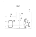
- the camera main body 14 is a shoulder type press camera. Further, the image light which passes through the lens device 16 passes through the ND filter 10, and passes through a color separation prism 18 which constitutes a color separation optical system, whereby the image light is subjected to color separation into three colors of R, G and B, which reach imaging elements 20, 22 and 24 provided at respective radiant ends of R, G and B of the color separation prism 18 as in Fig. 2 . Further, the camera main body 14 is loaded with a signal processing circuit (not illustrated) or the like which generates a video signal of a predetermined mode (NTSC or the like) by applying predetermined processing (white balance, y correction and the like) to the imaging signals obtained from the imaging elements 20, 22 and 24.
- NTSC predetermined mode
- the ND filter 10 is a received light amount regulating device which regulates the amount of light of a subject image which passes through the lens device 16 as in Fig. 1 and an optical system 28 of Fig. 2 fitted to the lens device 16, and regulates the amount of received light caused to form images in the imaging elements 20, 22 and 24.
- a form in which the ND filter 10 is incorporated in the camera main body 14 is shown, but the ND filter 10 may be incorporated in the lens device 16.
- the ND filter 10 may also be configured as an adaptor so as to be detachably attached between the camera main body 14 and the lens device 16.
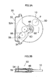
- Figs. 3A and 3B are a front view and a cross-sectional view showing a filter rotating mechanism 30 of the ND filter 10.
- the front view of the filter rotating mechanism 30 refers to the view of the filter rotating mechanism 30 seen from the lens device 16 side.
- Fig. 4 is a front view of the ND filter 10
- Fig. 5 is a developed sectional view of the ND filter 10
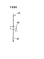
- Fig. 6 is a vertical sectional view of the ND filter 10.
- a transparent glass board 32 formed into a disk shape is used as a base material, a first region 34 with a light transmittance of about 100%, and a second region 36 with the light transmittance continuously changing stepwise are continuously formed in a circumferential direction of the transparent glass board 32.
- the second region 36 is formed by dividing, and changing the thickness of the ND coat 38, which is an optical film, into three stages in small regions 40, 42 and 44.
- a transparent resin board may be used as the base material in place of the transparent glass board 32. Both the transparent glass board 32 and the transparent resin board have favorable light transmittances and can be easily produced.
- the light transmittance of the first region 34 is not limited to about 100%, and the ND coat 38 may be formed in this region so that the light transmittance may be made less than 100%, but the higher the transmittance, the better.
- the first region 34 is formed in the range of 144° in the counterclockwise direction with a horizontal reference line H horizontally extending to the right side in Fig. 4 set as 0°.
- the second region 36 is formed to continue from the first region 34 in the range of 216° from the position at 144° to 360°.
- the small region 40 constituting the second region 36 is formed in the range of 72° from the position at 144° to 216°.
- the small region 42 is formed in the range of 72° from the position at 216° to 288°, and the small region 44 is formed in the range of 72° from the position at 288° to 360°.
- the light transmittance of the small region 40 is set at 25% (1/4) by the thickness of the ND coat 38.
- the light transmittance of the small region 42 is set at 6.3% (1/16), and the light transmittance of the small region 44 is set at 1.6% (1/64).
- an antireflection film 46 is formed on the surfaces (surfaces at the side of the lens device 16) of the first regions 34 and the second region 36.
- the antireflection film 46 with a reflectivity of less than 2% in 420 nm to 660 nm, which is required for the optical component of a camera, is used.
- the ND filter 10 thus constituted is rotatably supported by the filter rotating mechanism 30 shown in Fig. 3 via a pin 48 fixed to an aperture 11 of its center.
- the posture of the ND filter 10 when its center angle in the angle range of the first region 34 with the light transmittance of about 100% is aligned with an optical axis P of the image light is set as a home position. From this posture, the ND filter 10 is rotated to the region with a smaller light transmittance from the region with a larger light transmittance with respect to a passage area 50 of the image light, for example.
- the filter rotating mechanism 30 has a housing 52 which rotatably supports the ND filter 10 via the pin 48, and a gear train which rotatably drives the ND filter 10 is rotatably mounted to a front board 52A of the housing 52.
- the ND filter 10 may be rotated by electric power by connecting the output shaft of a motor to the input shaft 54, or may be rotated manually by a cameraperson by projecting the input shaft 54 outward from the camera main body 14.
- the cameraperson can perform photographing while continuously regulating the amount of received light.
- the small region 44 with a light transmittance of 1.6% is used in the case of excessively bright outdoors
- the first region 34 with a light transmittance of about 100% is used in the case of the excessively dark interior of a building
- photographing can be performed while the amount of received light during that while is changed stepwise in the small region 42 and the small region 44.
- a light amount sensor is provided at the television camera 12, and the ND filter 10 may be automatically controlled electrically based on the brightness of a photographing place which is output from the light amount sensor so that when the photographing place is excessively bright, the amount of received light is decreased, and when the place is excessively dark, the amount of received light is increased.
- the light amount is regulated by properly rotating the ND filter 10
- photographing can be performed with an f number with high resolving power of the lens used without rotating the iris ring of the lens, and therefore, a video with good quality can be obtained.
- the region where image light does not transmit does not traverse the passage area 50 of the image light at the time of operation of light amount regulation, and therefore, the screen does not become dark momentarily at the time of operation of light amount regulation. Therefore, by using the ND filter 10, a video with favorable quality which does not give sense of discomfort to a viewer can be obtained.
- the antireflection film 46 is formed on the surfaces of the first region 34 and the second region 36, and therefore, reflection of image light can be suppressed by the antireflection film 46. Accordingly, if the ND filter 10 is used, occurrence of a ghost can be suppressed, and an image with favorable quality can be obtained.
- a video with favorable quality which does not give sense of discomfort to a viewer can be obtained similarly to the effect of the single ND filter 10.
- the antireflection film 46 can be applied to the entire surface by one deposition by regulating the optical constant of the deposition substance for antireflection.
- the ND filter can be constructed by assembling a plurality of sector ND filters differing in densities in the disk shape, but in such a case, the light which is irregularly reflected becomes flare at the boundary portions in which a plurality of sector filters are connected, and degrades the video quality. Further, since a plurality of sector shapes are assembled, inclination precision to the optical axis of each area (each piece) slightly differs, the light beam is curved, and when switched, the position of an image is likely to move slightly. Therefore, according to the ND filter 10 of the embodiment with one transparent glass board 32 as a base material, such a trouble does not occur.
- the ND coat 38 of a predetermined thickness is deposited on only the small region 40, the ND filter with the light transmittance (1/4) is formed, and the antireflection film 46 is formed on the small region 40.
- the ND coat 38 is formed stepwise on the region 36, and the antireflection film 46 is formed on the surface layer thereof.
- the antireflection film 46 is formed on the region 34. According to this procedure, the ND filter 10 is produced.
- the ND filter 10 can be produced without any problem by the aforementioned manufacturing method, but there is the following cause for concern.
- the ND coat 38 of a predetermined thickness is ordinarily formed in each of small regions 40, 42 and 44 by setting an individual condition to each region, and due to variation in jig precision and variation in manufacture, variation occurs to the finished quality of the edges of the ND coat 38 of the small regions 40, 42 and 44.
- the manufacturing method of the ND filter which will be described hereinafter eliminates the above described causes of concern, and is the manufacturing method of the embodiment of the invention of the present application. More specifically, the manufacturing method of the embodiment is a manufacturing process in which while the region to be coated is extended to each of small regions 40, 42 and 44 from the small region 44 with a high finished ND density toward the small regions 42 and 40 with low ND densities in all the regions on which the ND coat 38 is formed, coating is applied to the small regions 42 and 40 at the downstream side from the small region 44 at the upstream side, and thereby, variation in the finished quality of the edges of the coat area can be suppressed to the minimum.
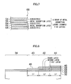
- the ND coat is made one absorption layer group 68 in which three dielectric layers 64, 64 and 64, and two metal absorption layers 66 and 66 are alternately stacked in five layers as shown in Fig. 7 .
- the dielectric layer 64 is of [MgF 2 ]
- the metal absorption layer 66 is [inconel] (trade name by Inco Ltd.: the metal film with Ni as a main component).
- the absorption layer groups 68 are stacked in layers on the small region 44 with the light transmittance (1/64), two of the absorption layer groups 68 are stacked in layers on the small region 42 with the light transmittance (1/16) and one absorption layer group 68 is placed on the small region 40 with the light transmittance (1/4), whereby a desired light transmittance is obtained, and the uniform antireflection film 46 is finally formed on the transparent glass board 32 to obtain an effective antireflection effect.
- the first absorption layer group 68 is formed on the small region 44 which ultimately has the light transmittance (1/64) first.
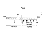
- the transparent glass board 32 is held in a coat furnace, and as shown in Figs. 9 and 10A , a jig 72 called a coat fixture with an aperture 70 having an angle of aperture of 72° being formed is used for only the small region 44 on which the ND coat is desired to be formed.
- the absorption layer group 68 which is a deposition substance is formed on the small region 44 via the aperture 70.
- the other regions 34, 40 and 42 are covered with a mask portion 74 of the jig 72, and therefore, the first absorption layer group 68 is not deposited thereon.
- the second absorption layer group 68 is formed on the small region 44 and the small region 42 which ultimately has the light transmittance (1/16) as in Fig. 8 .
- a jig 78 in which an aperture 76 having an angle of aperture of 144° is used as shown in Fig. 10B .
- the other regions 34 and 40 are covered with a mask portion 79 of the jig 78, and therefore, the second absorption layer group 68 is not deposited thereon.
- the third absorption layer group 68 is formed on the small regions 44 and 42 and the small region 40 which ultimately has the light transmittance (1/4) as shown in Fig. 8 .
- a jig 82 in which an aperture 80 having an angle of aperture of 216° is used as shown in Fig. 10C .
- the other region 34 is covered with a mask portion 83 of the jig 82, and therefore, the third absorption layer group 68 is not deposited.
- the antireflection film 46 is formed on the entire transparent glass board 32 including the region 34 to be a transparent filter.
- a ring-shaped jig 84 with an angle of aperture of 360° can be used as in Fig. 10D .
- the problem that the edges of the ND coat adjacent in the small regions 40, 42 and 44 overlay one another and the problem that gaps are formed can be eliminated. Therefore, even if the brightness of the photographing environment momentarily changes, a ghost is prevented and video is not discontinued, and video without sense of discomfort can be provided.
- the ND coat is constituted of the absorption layer group 68 in which a plurality of dielectric layers 64 and metal absorption layers 66 are alternately stacked in layers, whereby the reflectivity can be suppressed to less than 2% which is necessary for the optical components of a camera, for example, by the interference action of light by a plurality of dielectric layers 64 and metal absorption layers 66 which are alternately stacked in layers, and the light transmittance can be regulated to a desired value by a plurality of metal absorption layers 66.
- the antireflection film 46 of the embodiment the one formed by stacking dielectric layers [MgF 2 ] and [ZrO 2 ] alternately in two layers is used.
- Figs. 11A to 11D are graphs each showing the relationship of the reflectivity (%) and the light transmittance (%) with respect to the wavelength (nm) when the light transmittance of 1/4 n is changed in three stages, by obtaining the relationship by a known arithmetic expression.
- the axis of ordinates of each of the graphs represents reflectivity (%) and light transmittance (%), and the axis of abscissa represents the wavelength (nm).
- the reflectivity (%) is shown by (R)
- the light transmittance (%) is shown by (T), respectively.
- the wavelength range which is generally used as a camera is 420 to 660 (nm).
- the refraction index of the dielectric layer [MgF 2 ] which constitutes the surface of the absorption layer group is 1.39
- the refraction index of the transparent board (transparent glass board) which is a base material is 1.51.
- the refraction indexes of the transparent board and the dielectric layer [MgF 2 ] are preferably made substantially the same like this.
- the common antireflection film is added to the transparent board and the absorption layer group, and therefore, the refractive indexes of the transparent board which is a base part of the antireflection film and the surface of the absorption layer group are idealistically the same, but by making the refraction indexes substantially the same ( ⁇ 0.2), the common antireflection film is enabled.
- the materials ([MgF 2 ]) of the members which are located on the interfaces between the stacked absorption layer groups are preferably the same.
- the joints of the absorption layer groups have the same refraction indexes. Consequently, the layer of one substance is made optically, and therefore, the interference action can be controlled by setting the thickness of the dielectric layer to be optimum.
- the region 34 (see Fig. 8 ) with the light transmittance of 100% shown in Fig. 11A has a reflectivity of less than 2% in the wavelength range of 420 to 660 (nm), and therefore, there is no problem as the optical component of a camera.
- the light transmittance of the calculation result is substantially 25% in the wavelength range of 420 to 660 (nm). Further, the reflectivity can be suppressed to less than 2% in the wavelength range of 420 to 660 (nm).
- the light transmittance of the calculation result is substantially 6.3% in the wavelength range of 420 to 660 (nm). Further, the reflectivity can be suppressed to less than 2% in the wavelength range of 420 to 660 (nm).
- the light transmittance of the calculation result is substantially 1.6% in the range of 420 to 660 (nm). Further, the reflectivity can be suppressed to less than 2% in the wavelength range of 420 to 660 (nm).
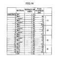
- Fig. 14 shows a mathematical table as one example of the film constitution which realizes the present invention.
- the mathematical table shows the layer constitution showing the refractive index and the thickness of each of the dielectric layer [MgF 2 ] and the metal absorption layer [inconel] of the absorption layer group, and the dielectric layers [MgF 2 ] and [ZrO 2 ] of the antireflective film.
- (1) shows the first absorption layer group
- (2) shows the second absorption layer group
- (3) shows the third absorption layer group
- (4) shows the antireflection film.
- the film constitution shown in the mathematical table is one example of the embodiment, and the film substances and the layer thickness of each of the layers are not limited to those of the present mathematical table, and they may be optional if only the dielectric layers and the metal film layers are alternately stacked.
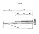
- the light transmittance of the calculation result is substantially 12.5% in the wavelength range of 420 to 660 (nm). Further, the reflectivity can be suppressed to less than 2% in the wavelength range of 420 to 660 (nm).
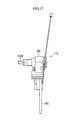
- Fig. 16 is a front view of the ND filter 10 in which a ring-shaped frame member 90 is attached to the peripheral edge portion of the transparent glass board 32. Further, Fig. 17 is a left side view of Fig. 16 , and Fig. 18 is a sectional view of a major portion of Fig. 16 .
- recessed portions 96, 98, 100 and 102 are provide at the peripheral edge portion of the frame member 90, and a leaf spring (urging member) 104 which engages with one of the recessed portions 96, 98, 100 and 102 is provided at the housing 92.
- the material of the frame member 90 is metal or resin.
- the recessed portions 96 to 102 can be provided on the frame member 90 by press forming. Further, when the frame member 90 is made of resin, the recessed portions 96 to 102 can be provided on the frame member 90 by injection molding.
- a flange 91 is provided at the inner peripheral portion of the frame member 90 as shown in Fig. 19 .
- the glass board 32 and the frame member 90 are fixed to each other in such a manner that the glass board 32 is dropped to the flange 91, and that an adhesive 106 is applied to the gap between the outer peripheral portion of the glass board 32 and the inner peripheral portion of the frame member 90.
- the glass board 32 and the frame member 90 can also be similarly fixed using the adhesive 106.
- the glass board 32 and the frame member 90 are preferably integrated with each other by molding the resin on the peripheral edge portion of the glass board 32.
- an input shaft 108 is rotatably provided on the rear surface side of the housing 92.
- a gear 110 shown by the two-dot chain line in Fig. 6 is connected coaxially with the input shaft 108.
- the gear 110 is in mesh with a gear 112 journaled by the housing 92, and the gear 112 is similarly in mesh with a gear 114 journaled by the housing 92. Further, the gear 114 is in mesh with a ring-shaped gear 116.
- each of the regions 34, 40, 42 and 44 is positioned at the optical axis P by the recessed portions 96 to 102 and the leaf spring 104.
- the ND filter 10 according to the embodiment is suitable for the case where it is manually operated by a cameraperson.
- the recessed portion is formed by cutting the peripheral edge portion of the glass board by a rotating grinding wheel, but it is very difficult to perform the cutting work without causing a chipping and a notch at the recessed portion at the time of the cutting work. Further, when the chipping and the notch are caused at the recessed portion, the glass board itself may be broken from the recessed portion as the starting point.
- the urging force of the leaf spring is directly transmitted to the glass board, so that the glass board is distorted to deteriorate the flatness of the glass board. This becomes the cause of deterioration of the optical characteristics of the ND filter.
- the peripheral edge portion of the glass board which portion is the sliding surface against the leaf spring, is easily scraped by the urging force of the leaf spring. This becomes the cause of the problem that the glass powder produced by the scraping adheres to other optical members to deteriorate the optical performance of a camera or a lens.
- the frame member 90 is not easily scraped by the urging force of the leaf spring 104, the problem of deterioration of the optical characteristics of the lens can also be solved.
Landscapes
- Physics & Mathematics (AREA)
- General Physics & Mathematics (AREA)
- Optics & Photonics (AREA)
- Engineering & Computer Science (AREA)
- Multimedia (AREA)
- Signal Processing (AREA)
- Blocking Light For Cameras (AREA)
- Optical Elements Other Than Lenses (AREA)
- Structure And Mechanism Of Cameras (AREA)
- Physical Vapour Deposition (AREA)
- Studio Devices (AREA)
- Optical Filters (AREA)
Applications Claiming Priority (3)
| Application Number | Priority Date | Filing Date | Title |
|---|---|---|---|
| JP2009097868 | 2009-04-14 | ||
| JP2009194682 | 2009-08-25 | ||
| JP2010022109A JP2011070150A (ja) | 2009-04-14 | 2010-02-03 | Ndフィルタ及びテレビカメラ並びにndフィルタの製造方法 |
Publications (2)
| Publication Number | Publication Date |
|---|---|
| EP2241910A2 true EP2241910A2 (fr) | 2010-10-20 |
| EP2241910A3 EP2241910A3 (fr) | 2013-08-14 |
Family
ID=42308547
Family Applications (1)
| Application Number | Title | Priority Date | Filing Date |
|---|---|---|---|
| EP10159817.5A Withdrawn EP2241910A3 (fr) | 2009-04-14 | 2010-04-13 | Filtre ND et caméra de télévision et procédé de fabrication du filtre ND |
Country Status (3)
| Country | Link |
|---|---|
| US (1) | US20100259824A1 (fr) |
| EP (1) | EP2241910A3 (fr) |
| JP (1) | JP2011070150A (fr) |
Families Citing this family (14)
| Publication number | Priority date | Publication date | Assignee | Title |
|---|---|---|---|---|
| US8908081B2 (en) | 2010-09-09 | 2014-12-09 | Red.Com, Inc. | Optical filter opacity control for reducing temporal aliasing in motion picture capture |
| EP2511761A3 (fr) * | 2011-04-14 | 2014-08-27 | Canon Kabushiki Kaisha | Appareil de prise de vue et filtre à densité neutre |
| CN103765274B (zh) * | 2011-08-31 | 2015-05-20 | 富士胶片株式会社 | 镜头装置和具有该镜头装置的成像装置 |
| WO2013073502A1 (fr) * | 2011-11-15 | 2013-05-23 | 富士フイルム株式会社 | Unité de filtrage nd, système d'imagerie et procédé de fabrication d'un filtre nd |
| CN104246544B (zh) * | 2012-04-26 | 2017-03-22 | 旭硝子株式会社 | 光学元件 |
| CN104603687B (zh) | 2012-08-31 | 2017-09-08 | 佳能电子株式会社 | 光量调整装置、摄像光学系统、以及摄像装置 |
| JP6422942B2 (ja) * | 2013-04-05 | 2018-11-14 | レッド.コム,エルエルシー | カメラ用光学的フィルタリング |
| US10944917B2 (en) * | 2013-09-16 | 2021-03-09 | Kyle L. Baltz | Camera and image processing method |
| JP6685040B2 (ja) * | 2015-11-24 | 2020-04-22 | カムイ・イノベーション株式会社 | ゴースト低減装置およびこれを備えた撮像装置、ゴースト低減方法、ならびに撮像光学系 |
| CN105607173B (zh) * | 2016-01-07 | 2018-09-14 | 西安工业大学 | 圆形径向渐变中性密度滤光片及其制备方法和装置 |
| KR20180025591A (ko) * | 2016-09-01 | 2018-03-09 | 삼성전자주식회사 | 자율 주행 차량을 위한 비전 센서의 제어 방법 및 장치 |
| CN110093589B (zh) * | 2018-01-31 | 2023-10-20 | 吉林大学 | 一种制备渐变中性密度滤光片的真空磁控溅射镀膜装置 |
| WO2019155908A1 (fr) | 2018-02-09 | 2019-08-15 | ソニー株式会社 | Unité de filtre, procédé de sélection de filtre et dispositif d'imagerie |
| JP7041831B1 (ja) * | 2021-03-01 | 2022-03-25 | 好英 湯本 | ターレット式光学素子装置、ターレット式光学素子装置に用いられる光学素子部、ターレット式光学素子装置に用いられるターレット、ターレット式光学素子装置とレンズレスカメラを備えたカメラ |
Citations (1)
| Publication number | Priority date | Publication date | Assignee | Title |
|---|---|---|---|---|
| JPH0993485A (ja) | 1995-09-25 | 1997-04-04 | Fuji Photo Optical Co Ltd | テレビジョンカメラ用回転フィルタ装置 |
Family Cites Families (17)
| Publication number | Priority date | Publication date | Assignee | Title |
|---|---|---|---|---|
| FR2455751A1 (fr) * | 1979-05-02 | 1980-11-28 | Thomson Csf | Systeme recepteur optoelectrique multispectral a haute dynamique |
| JPS6119585Y2 (fr) * | 1979-10-25 | 1986-06-12 | ||
| DE3636684A1 (de) * | 1986-10-28 | 1988-05-11 | Rodenstock Optik G | Filter zur kompensation des helligkeitsabfalls in der bildebene eines objektives |
| US5302449A (en) * | 1992-03-27 | 1994-04-12 | Cardinal Ig Company | High transmittance, low emissivity coatings for substrates |
| JP3359114B2 (ja) * | 1993-08-26 | 2002-12-24 | キヤノン株式会社 | 薄膜型ndフィルター及びその製造方法 |
| US6078442A (en) * | 1997-06-27 | 2000-06-20 | Asahi Seimitsu Kabushiki Kaisha | ND filter |
| JP3771678B2 (ja) * | 1997-07-28 | 2006-04-26 | ペンタックス株式会社 | Ndフィルター |
| US6553175B2 (en) * | 2000-01-21 | 2003-04-22 | Sycamore Networks, Inc. | Variable optical attenuator |
| CN100421025C (zh) * | 2001-10-12 | 2008-09-24 | 佳能株式会社 | 光量调整装置及具有该光量调整装置的光学系统和摄影装置 |
| JP2004037545A (ja) * | 2002-06-28 | 2004-02-05 | Nisca Corp | Ndフィルタ及びこれを用いた絞り装置 |
| US7042662B2 (en) * | 2002-12-26 | 2006-05-09 | Canon Kabushiki Kaisha | Light amount adjusting device, and optical device using the light amount adjusting device |
| JP2004295015A (ja) * | 2003-03-28 | 2004-10-21 | Nidec Copal Corp | Ndフィルタ及びその製造方法 |
| JP2004333553A (ja) * | 2003-04-30 | 2004-11-25 | Canon Inc | 光量調節装置、撮影装置及びフィルタ |
| JP2005070431A (ja) * | 2003-08-25 | 2005-03-17 | Canon Inc | 光量調節装置及び撮影装置 |
| JP2006227432A (ja) * | 2005-02-18 | 2006-08-31 | Nisca Corp | 光学フィルタの製造方法及びこれを用いた光学フィルタ並びに光量調整装置 |
| JP2007243928A (ja) * | 2006-02-09 | 2007-09-20 | Nippon Hoso Kyokai <Nhk> | テレビカメラ用グラデーションndフィルタユニット及びndアダプタ並びにテレビカメラ |
| JP2008276112A (ja) * | 2007-05-07 | 2008-11-13 | Canon Electronics Inc | Ndフィルタ |
-
2010
- 2010-02-03 JP JP2010022109A patent/JP2011070150A/ja active Pending
- 2010-04-13 US US12/759,067 patent/US20100259824A1/en not_active Abandoned
- 2010-04-13 EP EP10159817.5A patent/EP2241910A3/fr not_active Withdrawn
Patent Citations (1)
| Publication number | Priority date | Publication date | Assignee | Title |
|---|---|---|---|---|
| JPH0993485A (ja) | 1995-09-25 | 1997-04-04 | Fuji Photo Optical Co Ltd | テレビジョンカメラ用回転フィルタ装置 |
Also Published As
| Publication number | Publication date |
|---|---|
| EP2241910A3 (fr) | 2013-08-14 |
| JP2011070150A (ja) | 2011-04-07 |
| US20100259824A1 (en) | 2010-10-14 |
Similar Documents
| Publication | Publication Date | Title |
|---|---|---|
| EP2241910A2 (fr) | Filtre ND et caméra de télévision et procédé de fabrication du filtre ND | |
| JP7263643B2 (ja) | 広角可変式中性濃度フィルタ | |
| US20100176281A1 (en) | Optical element, imaging optical system, and camera module | |
| TWI528102B (zh) | 光圈裝置,攝影機及電子機器 | |
| JP2010117472A (ja) | 光学素子及びそれを有する光学系 | |
| CN112379506A (zh) | 含有塑胶透镜的成像透镜组、成像镜头模块及电子装置 | |
| US7349604B2 (en) | Method and apparatus for aligning optical components | |
| WO2011052325A1 (fr) | Module de lentilles, dispositif d'imagerie et procédé de fabrication du module de lentilles | |
| CN111505746B (zh) | 复合光学元件、光学装置和摄像装置 | |
| CN102692662B (zh) | 光学滤光器以及摄像装置 | |
| US7006141B1 (en) | Method and objective lens for spectrally modifying light for an electronic camera | |
| JP2016167048A (ja) | 光量調節装置、レンズ鏡筒、および光学装置 | |
| JP2013152369A (ja) | 絞り装置およびカメラ | |
| JPH075362A (ja) | ズームレンズのフォーカシング方式 | |
| JP5493057B2 (ja) | レンズ装置及びこのレンズ装置が装着される撮像装置 | |
| JP2007178822A (ja) | 光量絞り用ndフィルタ | |
| EP4075172B1 (fr) | Visiocasque, persienne, dispositif optique et procédé de fabrication de persienne | |
| JP2009037180A (ja) | 樹脂製光学素子用多層薄膜真空蒸着方法とその樹脂製光学素子を持つ撮影素子 | |
| US6088175A (en) | Optical filter apparatus | |
| CN118091872B (zh) | 一种小体积可变光栏镜头 | |
| EP3185534B1 (fr) | Dispositif de caméra avec réduction de halo rouge | |
| TWI362562B (en) | Aperture and method | |
| EP1574896A1 (fr) | Polariseur et procédé de fabrication de celui-ci | |
| CN111885292A (zh) | 摄像机构及电子设备 | |
| CN100432712C (zh) | 中灰滤光片及具有中灰滤光片的可变光阑装置和光学设备 |
Legal Events
| Date | Code | Title | Description |
|---|---|---|---|
| PUAI | Public reference made under article 153(3) epc to a published international application that has entered the european phase |
Free format text: ORIGINAL CODE: 0009012 |
|
| AK | Designated contracting states |
Kind code of ref document: A2 Designated state(s): AT BE BG CH CY CZ DE DK EE ES FI FR GB GR HR HU IE IS IT LI LT LU LV MC MK MT NL NO PL PT RO SE SI SK SM TR |
|
| AX | Request for extension of the european patent |
Extension state: AL BA ME RS |
|
| RAP1 | Party data changed (applicant data changed or rights of an application transferred) |
Owner name: FUJIFILM CORPORATION Owner name: NIPPON HOSO KYOKAI |
|
| RIC1 | Information provided on ipc code assigned before grant |
Ipc: G02B 26/02 20060101ALI20130320BHEP Ipc: G02B 5/20 20060101AFI20130320BHEP |
|
| PUAL | Search report despatched |
Free format text: ORIGINAL CODE: 0009013 |
|
| AK | Designated contracting states |
Kind code of ref document: A3 Designated state(s): AT BE BG CH CY CZ DE DK EE ES FI FR GB GR HR HU IE IS IT LI LT LU LV MC MK MT NL NO PL PT RO SE SI SK SM TR |
|
| AX | Request for extension of the european patent |
Extension state: AL BA ME RS |
|
| RIC1 | Information provided on ipc code assigned before grant |
Ipc: G02B 5/20 20060101AFI20130705BHEP Ipc: G02B 26/02 20060101ALI20130705BHEP |
|
| STAA | Information on the status of an ep patent application or granted ep patent |
Free format text: STATUS: THE APPLICATION IS DEEMED TO BE WITHDRAWN |
|
| 18D | Application deemed to be withdrawn |
Effective date: 20140215 |