EP2242063A2 - Matériaux de poison consumables et appareils pour réacteurs nucléaires et leurs procédés d'utilisation - Google Patents
Matériaux de poison consumables et appareils pour réacteurs nucléaires et leurs procédés d'utilisation Download PDFInfo
- Publication number
- EP2242063A2 EP2242063A2 EP20100160137 EP10160137A EP2242063A2 EP 2242063 A2 EP2242063 A2 EP 2242063A2 EP 20100160137 EP20100160137 EP 20100160137 EP 10160137 A EP10160137 A EP 10160137A EP 2242063 A2 EP2242063 A2 EP 2242063A2
- Authority
- EP
- European Patent Office
- Prior art keywords
- burnable poison
- example embodiment
- nuclear reactor
- burnable
- component
- Prior art date
- Legal status (The legal status is an assumption and is not a legal conclusion. Google has not performed a legal analysis and makes no representation as to the accuracy of the status listed.)
- Granted
Links
Images


Classifications
-
- G—PHYSICS
- G21—NUCLEAR PHYSICS; NUCLEAR ENGINEERING
- G21G—CONVERSION OF CHEMICAL ELEMENTS; RADIOACTIVE SOURCES
- G21G1/00—Arrangements for converting chemical elements by electromagnetic radiation, corpuscular radiation or particle bombardment, e.g. producing radioactive isotopes
- G21G1/02—Arrangements for converting chemical elements by electromagnetic radiation, corpuscular radiation or particle bombardment, e.g. producing radioactive isotopes in nuclear reactors
-
- G—PHYSICS
- G21—NUCLEAR PHYSICS; NUCLEAR ENGINEERING
- G21C—NUCLEAR REACTORS
- G21C7/00—Control of nuclear reaction
- G21C7/02—Control of nuclear reaction by using self-regulating properties of reactor materials, e.g. Doppler effect
- G21C7/04—Control of nuclear reaction by using self-regulating properties of reactor materials, e.g. Doppler effect of burnable poisons
-
- G—PHYSICS
- G21—NUCLEAR PHYSICS; NUCLEAR ENGINEERING
- G21G—CONVERSION OF CHEMICAL ELEMENTS; RADIOACTIVE SOURCES
- G21G1/00—Arrangements for converting chemical elements by electromagnetic radiation, corpuscular radiation or particle bombardment, e.g. producing radioactive isotopes
- G21G1/001—Recovery of specific isotopes from irradiated targets
- G21G2001/0094—Other isotopes not provided for in the groups listed above
-
- Y—GENERAL TAGGING OF NEW TECHNOLOGICAL DEVELOPMENTS; GENERAL TAGGING OF CROSS-SECTIONAL TECHNOLOGIES SPANNING OVER SEVERAL SECTIONS OF THE IPC; TECHNICAL SUBJECTS COVERED BY FORMER USPC CROSS-REFERENCE ART COLLECTIONS [XRACs] AND DIGESTS
- Y02—TECHNOLOGIES OR APPLICATIONS FOR MITIGATION OR ADAPTATION AGAINST CLIMATE CHANGE
- Y02E—REDUCTION OF GREENHOUSE GAS [GHG] EMISSIONS, RELATED TO ENERGY GENERATION, TRANSMISSION OR DISTRIBUTION
- Y02E30/00—Energy generation of nuclear origin
- Y02E30/30—Nuclear fission reactors
Definitions
- Example embodiments and methods generally relate to materials and components used in reactors of nuclear power plants.
- nuclear power plants include a reactor core having fuel arranged therein to produce power by nuclear fission.
- a common design in U.S. nuclear power plants is to arrange fuel in a plurality of fuel rods bound together as a fuel assembly, or fuel bundle, placed within the reactor core. Power is generated by the nuclear fuel, typically uranium, through a fission chain reaction of the fuel atoms.
- Managing and maintaining a steady-state fission reaction and corresponding power production and safety standards is achieved by managing the amount of neutrons and neutron flux within the core.
- Managing neutron flux may achieve several goals, including, for example, maximizing power production, equalizing fuel neutron exposure and fissioning or "bum,” minimizing neutron flux peaking, and providing safety margins for safe operation and shut-down of the reactor.
- Burnable poisons are one form of neutron flux management conventionally used in nuclear reactors. Burnable poisons typically absorb neutron flux, thereby reducing or "poisoning" fuel reactivity and fission rate, where they are placed. Based on the engineer's knowledge of the reactor core and reactor physics, the engineer can determine areas of the core subject to unwanted amounts of neutron flux at particular points in time during operation and place burnable poisons in those positions. Thus, unwanted flux may be reduced, resulting in a more even and/or safer bum throughout the fuel. Alternatively, burnable poisons may be placed in the core coolant or moderator and reduce reactivity throughout the core, potentially providing easier shut-down of the core and/or reducing reliance on other neutron flux management approaches, such as control rod/blade usage.
- Burnable poisons also conventionally have a reduced effect as time passes in an operating core. The more neutrons a particular burnable poison absorbs, the lesser its ability to continue absorbing neutrons. Through this property, burnable poisons may be used to control neutron flux or reactivity at specific time periods subject to unwanted amounts of neutron flux, such as beginning of operating cycles, while having minimal effect at other time periods where the poisoning effect is undesired, such as end of operating cycles.
- burnable poisons include, for example, gadolinium and/or boron compounds. These and related elements have a high absorption cross-section, or probability, for thermal neutron flux commonly found in light water reactors. As the burnable poisons absorb neutrons and lower reactivity, they are converted into other elements with much lower thermal neutron absorption cross-sections, thereby "burning out” over time in the operating core. Gadolinium and/or boron compounds are conventionally fashioned into special rods or fuel additives. In these forms, burnable poisons may be placed at specific axial and radial locations within the core to reduce unwanted levels of neutron flux predicted or experienced at those locations at certain times. Conventional burnable poison elements may be removed from the core and disposed of at the completion of each operating cycle, and new burnable poison elements may be introduced to replace the old, depending on new core characteristics.
- Example embodiments are directed to materials useable as burnable poisons in nuclear reactors.
- Example embodiment burnable poison materials may absorb neutron flux, or reduce reactivity, at desired positions within an operating nuclear reactor.
- Example embodiment materials may have a substantially reduced absorption effect with increased exposure to neutron flux.
- Example embodiment burnable poison materials produce desired daughter products as they bum out, thereby permitting placement and use for neutronic characteristic improvement and/or neutron flux shielding in locations conventionally barred as uneconomical.
- Example embodiment burnable poison materials may include natural iridium and enriched iridium-193, for example.
- Example embodiments include fuel components and/or other reactor components fabricated from and/or containing a desired amount of example embodiment burnable poison materials.
- Example embodiments may be fabricated, shaped, and placed to provide desired burnable poison effects in the reactor core in conventional locations and locations not conventionally used due to economic infeasibility.
- Example methods include use of example embodiment components, including determining locations benefitting from burnable poison effects, fabricating example embodiment components of a desired amount of example embodiment burnable poison materials, placing the example embodiment components, exposing example embodiment components to flux within the operating nuclear reactor, removing example embodiment burnable poison components from the core, and/or harvesting example components for desired daughter products produced from example embodiment burnable poison materials.
- Example embodiments may use unconventional elements as burnable poisons for commercial or other nuclear reactors and may unexpectedly produce desired elements and isotopes thereof as they are used.
- Daughter products produced from burnt conventional burnable poisons may be of low value and/or chemically/radioactively unsafe, but example embodiments may produce daughter isotopes and elements produced that instead have value and significant other utility.
- an example embodiment burnable poison made of iridium may produce platinum through exposure to and absorption of neutron flux. The produced platinum may have increased value and alternative industrial applications and may not be dangerous and/or need to be disposed of, like conventional burnable poisons.
- example embodiment burnable poisons may be placed at positions in a nuclear reactor not conventionally utilized for conventional burnable poisons, because of the cost of such placement and/or disposal requirements of conventional burnable poisons. Such example placement may benefit neutronic characteristics of a nuclear reactor using example embodiment burnable poisons and produce additional desired materials.
- Example embodiment burnable poisons appreciably absorb neutron flux, including thermal neutron flux, commonly found in operating nuclear reactors. After sufficient exposure to the operating nuclear reactor, example burnable poisons convert to materials having substantially lower cross sections and do not appreciably absorb further neutron flux. The resulting materials possess other utility or value outside the reactor, and may be harvested for such use and/or value.
- Example embodiment burnable poisons may include natural iridium.
- Iridium is a hard metal resistant to corrosion that may be directly exposed to operating reactor conditions and sufficiently maintain its geometric characteristics so as to be used without shielding or containment within an operating nuclear reactor.
- Natural iridium includes stable isotopes iridium-191 ( ⁇ 37% abundance) and iridium-193 ( ⁇ 63% abundance).
- Iridium-191 has a thermal neutron cross section of about 750 barns and will undergo the following reaction when exposed to neutron flux in conventional light water nuclear reactors: Ir 191 + n 1 ⁇ Ir 192
- the produced iridium-192 is unstable and beta decays into platinum-192 with a half-life of approximately 74 days as such: Ir 192 ⁇ Pt 192 + ⁇
- the resulting platinum-192 is stable and has a cross section of approximately 14 barnswhich is less than one-tenth the cross-section of the parent example embodiment burnable poison iridium-191.
- iridium-193 The other natural iridium isotope, iridium-193, has a thermal neutron cross section of approximately 110 barns and will undergo the following reaction when exposed to neutron flux in commercial nuclear reactors: Ir 193 + n 1 ⁇ Ir 194
- the produced iridium-194 is unstable and beta decays into platinum-194 with a half-life of approximately 19 hours as such: Ir 194 ⁇ Pt 194 + ⁇
- the resulting platinum-194 is stable and has a cross section of approximately 1.1 barns, which is less than one-hundredth the cross-section of the parent example embodiment burnable poison iridium-193.
- natural iridium may function as a burnable poison, having a modest neutron absorption effect initially, and depending on the amount of iridium used and the flux of the operating reactor, having a negligible neutron absorption effect at a later point in time, once burnt.
- the amount and placement of natural iridium may be adjusted, depending on levels and types of flux encountered in the operating nuclear reactor, to produce a desired burnable poison effect, including reducing flux peaking and increasing shutdown margins.
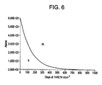
- Figure 6 illustrates an example burnable poison - one mole of iridium-191 - converted to platinum-192 over the duration of two years within a neutron flux of 1.44E14, which may be a common level of flux encountered in nuclear reactors.
- iridium may be substantially converted to platinum during commercial operating cycles such that mostly platinum may be harvested from the reactor during re-loading cycles.
- Example components that may be fabricated from natural iridium are discussed below.
- the produced platinum isotopes from example embodiment burnable poison natural iridium are stable and may have significant monetary value and/or industrial application.
- the produced platinum may be harvested directly from any burnable poison components fabricated out of natural iridium, once the remaining radioactive isotopes have decayed to safe levels of non-radioactive platinum.
- the platinum isotopes may be immediately harvested from burnable poison components fabricated of natural iridium, before the iridium-192 has decayed to negligibly radioactive levels, through chemical extraction in appropriate facilities having adequate radiation protection, such as hot cells and the like.
- the amount and placement of natural iridium used as an example embodiment burnable poison may be selected to ensure that the all the natural iridium is substantially converted to platinum by the end of a known operating cycle and post-cycle cool-down and fuel handling.
- burnable poisons may include isotopically separated iridium-193.
- natural iridium is approximately 63% iridium-193, which may be separated through known isotopic separation mechanisms such as centrifugal and gas-diffusion type isotope separation methods, for example.
- Resulting example embodiment burnable poisons may thus be substantially pure iridium-193.
- Pure iridium-193 may possess additional beneficial characteristics as an example embodiment burnable poison. As shown above, iridium-193 has a cross section over 100 times greater than the produced platinum-194 and a half-life on the order of hours. Thus, example embodiment burnable poison components fabricated from pure iridium-193 may have a more significant burnable poison effect and be harvested from nuclear reactors as substantially pure, non-radioactive platinum without requiring substantial decay time and/or chemical separation.
- example embodiment burnable poisons Various phases of materials may be used as example embodiment burnable poisons. It is understood that liquid or gaseous burnable poisons, or burnable poisons generating liquid or gaseous desirable daughter products, may also be used as example embodiment burnable poisons, with appropriate containment for placing and/or harvesting the material and/or product thereof.
- Solid example embodiment burnable poisons including natural iridium and iridium-193 discussed above, that produce only solid desired daughter products including platinum, may be formed and used directly as example embodiment burnable poison components, as discussed in the following section.
- Example embodiment burnable poison components may be fabricated from or contain any of the example burnable poisons discussed above, including natural iridium and/or highly-enriched iridium-193.
- Example components may be configured and placed in reactor locations benefiting from burnable poison presence, based on the knowledge of one skilled in the art regarding a particular reactor's physical and neutronic characteristics.
- Example components may be interchangeable with components conventionally found in nuclear reactors and/or may be new or specially designed, based on the material properties of the example burnable poison used and the configuration and needs of the particular reactor. For example, fuel bundle tie plates, extensions, channels, rod content, tubing, water rods, etc. may all be fabricated from or contain example embodiment burnable poisons.
- example components may be harvested for valuable and/or useable daughter products, including platinum, example components may be placed in areas of the reactor that may benefit from burnable poison presence but are not conventionally used, because of the cost of placement and disposal of conventional burnable poison components.
- burnable poison components may be used as local peaking control for fresh fuel components.
- FIG. 1 is an illustration of an example fuel assembly 100 having several example embodiment burnable poison components, whose features and effect on a reactor using the bundle 100 are discussed in turn.
- example fuel assembly 100 may include a plurality of full and/or part length fuel rods 118 and 119 arranged in a channel 120. Spacers 115 may provide transverse spacing and positioning among fuel rods 118 and 119.
- Water rods 110 may provide axial passages for water flow through example bundle 100.
- Upper tie plate 130 and lower tie plate 140 may provide connection and handling components at either end of example assembly 100.
- An example embodiment upper tie plate 130 and/or lower tie plate 140 may be at either end of fuel assembly 100.
- Example tie plates 130/140 may be fabricated of example burnable poisons. For example, natural iridium or enriched iridium-193 may be used to fabricate example embodiment upper tie plate 130 and lower tie plate 140. Because of the location, example tie plates 130/140 may absorb neutrons and produce a moderate poison effect at the top and bottom of a reactor core including one or more of example fuel assembly 100.
- Example embodiment upper tie plate 130 and lower tie plate 140 may include various amounts of example burnable poison in a number of different configurations. Depending on the amount of burnable poison used, example tie plates 130/140 may substantially convert to desired daughter products and absorb fewer neutrons near the completion of the operating cycle, when neutron flux out of the reactor is lower. Thus, particularly at the beginning of an operating cycle, example tie plates 130/140 may reduce the amount of neutron flux to which reactor components at the top and bottom of the core, such as a lower plenum, steam drying equipment, etc., are subjected, enhancing their performance and preventing brittling caused by lengthy exposure to neutron flux.
- example tie plates 130/140 may reduce the amount of neutron flux to which reactor components at the top and bottom of the core, such as a lower plenum, steam drying equipment, etc., are subjected, enhancing their performance and preventing brittling caused by lengthy exposure to neutron flux.
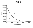
- Fig. 5 is a graph of a mole of iridium subjected to neutron flux, 3E13 n/cm 2 , typically encountered at the tie plates 130/140 over the course of several years.
- the example embodiments of iridium will be substantially converted to platinum over of approximately six to eight years, which corresponds to the average fuel bundle life in a core of a commercial nuclear reactor.
- Example embodiment tie plates 130/140 fabricated of iridium may additionally absorb neutron flux from the core and reducing flux, and negative effects of the same, to outside core components.
- any of the channel 120, spacer 115, water rods 110, and cladding for full length and part length rods 118/119 in FIG. 1 may be example embodiment burnable poison components fabricated out of example embodiment burnable poisons. Based on the neutronic characteristics of a particular reactor core, one skilled in the art may determine what example embodiment components are most effective at meeting operating and/or shielding criteria with a burnable poison and fabricate example bundle 100 out of an appropriate combination of conventional and example embodiment burnable poison components. Individual example embodiment components may be physically configured and contain amounts of example burnable poisons sufficient to meet these operating criteria.
- a reactor core may have known flux peaking at particular core positions during operation, and fuel bundles 100 placed at those areas may have additional example components fabricated from example burnable poisons, in order to both reduce the peaking and convert the example components into desired daughter products.
- example bundle 100 may be removed from the core and harvested for desired daughter products generated from the example embodiment burnable poison components. Such harvesting may require an extended decay time and/or chemical separation in order to isolate and harvest the desired daughter product. For example, if pure iridium-193 is used to fabricate the channel 120 with a thickness and placement within the core sufficient to bum all the iridium-193 into platinum-194, example assembly 100 having example embodiment channel 120 may be removed from the core, and example embodiment channel 120 may be removed from assembly 100 and used shortly thereafter as a platinum-194 source.
- FIG. 2 is an illustration of several example fuel bundles 100 and core components that may be fabricated or contain example embodiment burnable poisons. As shown in FIG. 2 , one or more example fuel bundles 100 containing example embodiment burnable poison components may be placed within a reactor core similar to conventional fuel placement. Control rods or cruciform control blades 160 may be placed at alternate bundle corners to absorb neutron flux and control reactivity. Fuel support 170 may support and align bundles 100 within the core.
- One or more example embodiment axial blankets 150 may be placed on exterior channels 120 of fuel bundles 100.
- Axial blankets 150 may be fabricated of example embodiment burnable poisons, including natural iridium and/or enriched iridium-193.
- Axial blankets may be placed at bundle intersections or other locations that benefit from a burnable poison effect at that location. For example, intersections lacking control blades 160 may be subject to higher flux peaking and resultant uneven bum and lowered shutdown margins at the beginning of a fuel cycle.
- Example embodiment axial blankets 150 at these positions may lower peaking and/or increase shutdown margins, increasing fuel efficiency and plant safety.
- the core engineer may model the core or otherwise predict positions benefitting from a burnable poison effect at particular points within a fuel cycle and place example embodiment axial blankets 150 at positions benefitting from a burnable poison effect according to such models or predictions.
- Example embodiment axial blankets 150 may further be fabricated of a thickness or other dimension that may provide a desired amount of burnable poison effect. Because example embodiment axial blankets 150 may be fabricated from an example burnable poison, such as iridium-193, that has a greatly reduced effect on neutron flux with increased absorbency of the same, a thicker axial blanket 150 may be used for positions needing increased burnable poison effects. Further, because axial blankets may be geometrically simple, use of iridium, which may be non-ductile and difficult to work, may be most economically feasible in example embodiment axial blankets 150, where extensive working in fabrication would not be required.
- an example burnable poison such as iridium-193
- a thicker axial blanket 150 may be used for positions needing increased burnable poison effects.
- axial blankets may be geometrically simple, use of iridium, which may be non-ductile and difficult to work, may be most economically feasible in example embodiment axial blankets 150, where extensive working in fabrication would not be required.
- Example embodiment axial blankets 150 may be attached directly to fuel bundles 100 via the channel 120 or other fuel component, or axial blankets 150 may be secured to other core components. Following exposure to the operating nuclear reactor and reduction and/or exhaustion of their flux-absorbing capacity, axial blankets 150 may be removed from the core, potentially with the removal of fuel bundles 100, and harvested for desired daughter products generated from example burnable poisons therein, including platinum.
- FIG. 6 is a graph of a mole of iridium subjected to neutron flux, 1.4E14 n/cm 2 , typically encountered at axial blankets 150 over the course of approximately 800 days. As shown in FIG. 6 , the example embodiment axial blankets 150 using iridium-191 as a burnable poison is substantially to platinum in approximately 800 days of operation, which roughly corresponds to a single, two-year commercial light water reactor fuel cycle.
- any of the fuel support 170, control blades 160, and/or other non-fuel core components may be example embodiment burnable poison components fabricated out of example embodiment burnable poisons. Based on the neutronic characteristics of a particular reactor core, one skilled in the art may determine what example embodiment components are most effective at meeting operating and/or shielding criteria with a burnable poison and fabricate components 150, 160, 170, etc. out of an appropriate combination of conventional and example embodiment burnable poison components and in appropriate dimensions. Individual example embodiment components may be physically configured and contain amounts of example burnable poisons sufficient to meet these operating criteria.
- FIG. 3 is an illustration of a cross-section of reactor core 300.
- Several example fuel bundles 100 and/or other core components fabricated from or containing example embodiment burnable poisons discussed above may be included in reactor core 300.
- one or more example embodiment perimeter blankets 320 containing example embodiment burnable poison components may be placed between fuel bundles 100 and reactor wall/ shroud 310.
- Example embodiment perimeter blankets 320 may be fabricated of example embodiment burnable poisons, including natural iridium and enriched iridium-193.
- Perimeter blankets 320 may be placed at locations that benefit from a burnable poison effect and/or at positions shielding critical core components from neutron flux.
- reactor wall 310 may become brittle over time and with exposure to high levels of neutron flux within an operating reactor core 300.
- Example embodiment perimeter blankets 320 shielding wall 310 may lower neutron-induced brittling, increasing core vessel life and safety.
- the core engineer may model the core or otherwise predict positions benefitting from a burnable poison effect at particular points within a fuel cycle and place example embodiment perimeter blankets 320 at positions benefitting from a burnable poison effect according to such models or predictions.
- Example embodiment perimeter blankets 320 may be fabricated of a thickness or other dimension that may provide a desired amount of burnable poison effect. Because example embodiment perimeter blankets 320 may be fabricated from an example burnable poison, such as iridium-193, that has a greatly reduced effect on neutron flux with increased absorbency of the same, a thicker perimeter blanket 320 may be used for positions needing increased burnable poison effects, including shielding effects. Further, because perimeter blankets 320 may be geometrically simple and use of iridium may be especially economically feasible in example embodiment perimeter blankets 320, where extensive working in fabrication may not be required.
- an example burnable poison such as iridium-193
- a thicker perimeter blanket 320 may be used for positions needing increased burnable poison effects, including shielding effects.
- perimeter blankets 320 may be geometrically simple and use of iridium may be especially economically feasible in example embodiment perimeter blankets 320, where extensive working in fabrication may not be required.
- Example embodiment perimeter blankets 320 may be attached directly to wall 310 and/or fuel bundles 100, or perimeter blankets 320 may be secured to other core components.
- Example embodiment perimeter blankets 320 may be fabricated into plate-like sheets, either flat or fabricated from a plurality of rods containing example burnable poisons, for example.
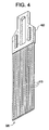
- Fig. 4 is an illustration of an example embodiment perimeter blanket 320 fabricated with burnable poison rods 410.
- the burnable poison rods 410 may be fabricated from hollow tubing containing example burnable poisons, such as natural or enriched iridium.
- Example embodiment blanket 320 may also include rods 410 that are solid or a solid flat plate.
- Perimeter blanket 320 may include a handle 420 secured to an end of blanket 320 to enable blade placement, movement, and/or other handling. As discussed with respect to other example embodiments containing example burnable poisons, example embodiment perimeter blankets 320 may be exposed to an operating nuclear reactor and slowly reduce and/or exhaust their flux-absorbing capacity. Example embodiment perimeter blankets 320 may be removed from the core and harvested for desired daughter products generated from example burnable poisons therein, including platinum.
- Example burnable poisons and example components containing the same being described, example methods of using the same are now discussed. It is understood that any of the above-discussed example components may be used with example methods, but example methods are not limited thereto. Similarly, it is understood that any of the above-discussed example burnable poison materials and desired daughter products may be used and generated with example methods, but example methods are not limited thereto.
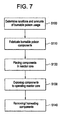
- FIG. 7 is a flow chart illustrating example methods.
- Example methods of using components including example embodiment burnable poisons include determining locations benefiting from burnable poison effects, including flux absorption and/or radiation shielding, in step S100.
- the determining may include a simulation of core flux amounts based on other core characteristics such as fuel placements and enrichments. Alternatively, the determining may be based on knowledge of one familiar with the core or based on past core performance.
- an amount of example embodiment burnable poison to be used, based on the absorption ability of the poison used, amount of flux to be absorbed, and amount of desired daughter product to be generated, may be determined.
- Step S100 may be implemented on a processing device or calculated by a core engineer.
- example embodiment components containing a desired amount of example embodiment burnable poison materials determined in Step S100 may be fabricated.
- Example embodiment components may closely resemble conventional components that they may replace.
- example embodiment components may have altered dimensions and/or geometries in order to accommodate the amount of burnable poison to be used as determined in step S 100.
- Example embodiment components may be fabricated wholly from example embodiment burnable poison materials or may include these materials, potentially in containment spaces within the components. Fabrication of example embodiments in step S110 may include known methods of forging, shaping, and otherwise working the material used to fabricate example embodiment components, including example embodiment burnable poisons.
- step S 120 the example embodiment components fabricated in Step S 110 are placed at the locations determined in step S 100 within the core.
- the placement in step S120 may occur during a fuel outage when the reactor core is accessible at the end of a fuel cycle. Placement may coincide with fuel assembly placement, particularly if example embodiment components are placed within or attached to fuel assemblies.
- step S130 example embodiment components containing example embodiment burnable poisons may be exposed to flux within the operating nuclear reactor.
- Step S 130 may include example embodiments providing the desired burnable poison effect within the operating core and generating desired daughter products as a result of such exposure.
- step S140 example embodiment burnable poison components may be removed and/or harvested for desired daughter products produced from the exposure in step S 130. Removal in step S 140 may occur during a fuel outage or another time when the reactor core is accessible, and may occur simultaneously with fuel shuffling / removal. Harvesting desired daughter products may include allowing example embodiment components to decay to safe radioactive levels or chemically separating desired products from other undesired and/or radioactive products.
- example embodiments and methods provide burnable poison effects and generation of desired daughter products at positions and in amounts and purities not possible in conventional fuel bundles and core components, example embodiments may permit more favorable reactor core neutronic characteristics, shielding, and safety with reduced operating costs due to the value of produced daughter products.
- example embodiments and methods thus being described, it will be appreciated by one skilled in the art that example embodiments may be varied through routine experimentation and without further inventive activity.
- example embodiments and methods may be discussed with reference to features and components conventionally found in US commercial light-water reactors for electrical power generation; however, example embodiments and methods may be useable with a variety of different types of reactors found worldwide. Variations are not to be regarded as departure from the spirit and scope of the exemplary embodiments, and all such modifications as would be obvious to one skilled in the art are intended to be included within the scope of the following claims.
Landscapes
- Physics & Mathematics (AREA)
- Engineering & Computer Science (AREA)
- Chemical & Material Sciences (AREA)
- Chemical Kinetics & Catalysis (AREA)
- Plasma & Fusion (AREA)
- General Engineering & Computer Science (AREA)
- High Energy & Nuclear Physics (AREA)
- General Chemical & Material Sciences (AREA)
- Monitoring And Testing Of Nuclear Reactors (AREA)
- Manufacture And Refinement Of Metals (AREA)
- Physical Or Chemical Processes And Apparatus (AREA)
Applications Claiming Priority (1)
| Application Number | Priority Date | Filing Date | Title |
|---|---|---|---|
| US12/385,747 US9165691B2 (en) | 2009-04-17 | 2009-04-17 | Burnable poison materials and apparatuses for nuclear reactors and methods of using the same |
Publications (3)
| Publication Number | Publication Date |
|---|---|
| EP2242063A2 true EP2242063A2 (fr) | 2010-10-20 |
| EP2242063A3 EP2242063A3 (fr) | 2013-01-23 |
| EP2242063B1 EP2242063B1 (fr) | 2015-10-07 |
Family
ID=42651205
Family Applications (1)
| Application Number | Title | Priority Date | Filing Date |
|---|---|---|---|
| EP10160137.5A Active EP2242063B1 (fr) | 2009-04-17 | 2010-04-16 | Matériaux de poison consommable et appareils pour réacteurs nucléaires et leurs procédés d'utilisation |
Country Status (7)
| Country | Link |
|---|---|
| US (1) | US9165691B2 (fr) |
| EP (1) | EP2242063B1 (fr) |
| JP (1) | JP2010249820A (fr) |
| CA (1) | CA2698877C (fr) |
| ES (1) | ES2553211T3 (fr) |
| RU (1) | RU2521591C2 (fr) |
| TW (1) | TWI500044B (fr) |
Cited By (3)
| Publication number | Priority date | Publication date | Assignee | Title |
|---|---|---|---|---|
| EP2722861A1 (fr) | 2012-10-22 | 2014-04-23 | ABB Technology AG | Agencement de limiteur de courant de défaut |
| CZ309520B6 (cs) * | 2018-12-27 | 2023-03-22 | České vysoké učení technické v Praze | Vyhořívající absorbátor pro jaderný reaktor |
| WO2024056314A1 (fr) * | 2022-09-13 | 2024-03-21 | Nuclear Research And Consultancy Group | Préparation d'isotopes pt à activité spécifique élevée à partir d'alliages d'ir |
Families Citing this family (5)
| Publication number | Priority date | Publication date | Assignee | Title |
|---|---|---|---|---|
| JP2012122770A (ja) * | 2010-12-06 | 2012-06-28 | Mitsubishi Heavy Ind Ltd | 燃料棒および燃料集合体 |
| US9431135B2 (en) | 2013-12-17 | 2016-08-30 | Global Nuclear Fuel—Americas, LLC | Nuclear reactor fluence reduction systems and methods |
| JP6517981B2 (ja) * | 2017-07-31 | 2019-05-22 | 株式会社東芝 | 燃料集合体の改修方法、燃料集合体の製造方法 |
| CN109273119B (zh) * | 2018-09-13 | 2022-02-11 | 中国核动力研究设计院 | 在临界装置上测量大反应性时优化中子探测器位置的方法 |
| CN117133490B (zh) * | 2023-07-25 | 2024-05-07 | 华能核能技术研究院有限公司 | 一种缩短球床式高温气冷初装堆芯建立过程的方法及系统 |
Family Cites Families (66)
| Publication number | Priority date | Publication date | Assignee | Title |
|---|---|---|---|---|
| US3594275A (en) | 1968-05-14 | 1971-07-20 | Neutron Products Inc | Method for the production of cobalt-60 sources and elongated hollow coiled wire target therefor |
| US3940318A (en) | 1970-12-23 | 1976-02-24 | Union Carbide Corporation | Preparation of a primary target for the production of fission products in a nuclear reactor |
| US3998691A (en) | 1971-09-29 | 1976-12-21 | Japan Atomic Energy Research Institute | Novel method of producing radioactive iodine |
| US4196047A (en) | 1978-02-17 | 1980-04-01 | The Babcock & Wilcox Company | Irradiation surveillance specimen assembly |
| US4284472A (en) | 1978-10-16 | 1981-08-18 | General Electric Company | Method for enhanced control of radioiodine in the production of fission product molybdenum 99 |
| FR2481506B1 (fr) | 1980-04-25 | 1986-08-29 | Framatome Sa | Dispositif de cloisonnement du coeur d'un reacteur nucleaire par des elements amovibles |
| FR2513797A1 (fr) | 1981-09-30 | 1983-04-01 | Commissariat Energie Atomique | Dispositif de protection neutronique superieure pour assemblage de reacteur nucleaire |
| US4564498A (en) | 1982-10-26 | 1986-01-14 | General Electric Company | System for the analysis of nuclear fuel rods |
| US4663111A (en) | 1982-11-24 | 1987-05-05 | Electric Power Research Institute, Inc. | System for and method of producing and retaining tritium |
| US4475948A (en) | 1983-04-26 | 1984-10-09 | The United States Of America As Represented By The Department Of Energy | Lithium aluminate/zirconium material useful in the production of tritium |
| US4532102A (en) | 1983-06-01 | 1985-07-30 | The United States Of America As Represented By The United States Department Of Energy | Producing tritium in a homogenous reactor |
| GB8321491D0 (en) | 1983-08-10 | 1983-09-14 | Atomic Energy Authority Uk | Nuclear fuel element |
| US4597936A (en) | 1983-10-12 | 1986-07-01 | Ga Technologies Inc. | Lithium-containing neutron target particle |
| JPS59133348A (ja) | 1983-12-12 | 1984-07-31 | Toshiba Corp | 中性子吸収材 |
| CS255601B1 (en) | 1984-05-18 | 1988-03-15 | Kristian Svoboda | 99 mtc elution unit-built generator and method of its production |
| GB8422852D0 (en) | 1984-09-11 | 1984-11-07 | Atomic Energy Authority Uk | Heat pipe stabilised specimen container |
| JPS61147183A (ja) | 1984-12-21 | 1986-07-04 | 株式会社日立製作所 | 燃料集合体 |
| US4729903A (en) | 1986-06-10 | 1988-03-08 | Midi-Physics, Inc. | Process for depositing I-125 onto a substrate used to manufacture I-125 sources |
| US4859431A (en) | 1986-11-10 | 1989-08-22 | The Curators Of The University Of Missouri | Rhenium generator system and its preparation and use |
| US5145636A (en) | 1989-10-02 | 1992-09-08 | Neorx Corporation | Soluble irradiation targets and methods for the production of radiorhenium |
| US5053186A (en) | 1989-10-02 | 1991-10-01 | Neorx Corporation | Soluble irradiation targets and methods for the production of radiorhenium |
| LU87684A1 (de) | 1990-02-23 | 1991-10-08 | Euratom | Verfahren zur erzeugung von aktinium-225 und wismut-213 |
| EP0469616B1 (fr) | 1990-08-03 | 1996-05-01 | Kabushiki Kaisha Toshiba | Coeur de réacteur permettant la transmutation d'éléments transuraniens, barre combustible permettant la transmutation d'éléments transuraniens, assemblage combustible permettant la transmutation d'éléments transuraniens |
| US5596611A (en) | 1992-12-08 | 1997-01-21 | The Babcock & Wilcox Company | Medical isotope production reactor |
| GB2282478B (en) | 1993-10-01 | 1997-08-13 | Us Energy | Method of fabricating 99Mo production targets using low enriched uranium |
| US5633900A (en) | 1993-10-04 | 1997-05-27 | Hassal; Scott B. | Method and apparatus for production of radioactive iodine |
| RU2100851C1 (ru) | 1993-12-22 | 1997-12-27 | Сибирский химический комбинат | Топливная сборка ядерного реактора |
| US6490330B1 (en) | 1994-04-12 | 2002-12-03 | The Regents Of The University Of California | Production of high specific activity copper -67 |
| US5513226A (en) | 1994-05-23 | 1996-04-30 | General Atomics | Destruction of plutonium |
| US5871708A (en) | 1995-03-07 | 1999-02-16 | Korea Atomic Energy Research Institute | Radioactive patch/film and process for preparation thereof |
| JP3190005B2 (ja) | 1996-03-05 | 2001-07-16 | 日本原子力研究所 | 放射化ベリリウムのリサイクル方法 |
| JP3419997B2 (ja) | 1996-06-26 | 2003-06-23 | 株式会社日立製作所 | 燃料集合体と該燃料集合体用のチャンネルボックスの製造方法 |
| US5682409A (en) | 1996-08-16 | 1997-10-28 | General Electric Company | Neutron fluence surveillance capsule holder modification for boiling water reactor |
| US5910971A (en) | 1998-02-23 | 1999-06-08 | Tci Incorporated | Method and apparatus for the production and extraction of molybdenum-99 |
| JP3781331B2 (ja) | 1998-06-05 | 2006-05-31 | 独立行政法人 日本原子力研究開発機構 | 血管再狭窄予防用キセノンー133の製造方法 |
| US6233299B1 (en) * | 1998-10-02 | 2001-05-15 | Japan Nuclear Cycle Development Institute | Assembly for transmutation of a long-lived radioactive material |
| JP2000298187A (ja) | 1999-04-15 | 2000-10-24 | Japan Nuclear Cycle Development Inst States Of Projects | 原子炉用燃料要素 |
| DE60007053T2 (de) | 1999-10-14 | 2004-10-21 | Toshiba Kawasaki Kk | Kernbrennstabbündel und Kernreaktor |
| JP2003513938A (ja) | 1999-11-09 | 2003-04-15 | フォルシュングスツェントルム カールスルーエ ゲゼルシャフト ミット ベシュレンクテル ハフツング | 希土類を含有している混合物及びその使用 |
| SE516045C2 (sv) * | 2000-03-20 | 2001-11-12 | Westinghouse Atom Ab | Komponent innefattande en zirkoniumlegering, förfarande för att tillverka nämnda komponent samt en nukleär anläggning innefattande nämnda komponent |
| AUPQ641100A0 (en) | 2000-03-23 | 2000-04-15 | Australia Nuclear Science & Technology Organisation | Methods of synthesis and use of radiolabelled platinum chemotherapeutic ag ents |
| US6456680B1 (en) | 2000-03-29 | 2002-09-24 | Tci Incorporated | Method of strontium-89 radioisotope production |
| FR2811857B1 (fr) | 2000-07-11 | 2003-01-17 | Commissariat Energie Atomique | Dispositif de spallation pour la production de neutrons |
| US6678344B2 (en) | 2001-02-20 | 2004-01-13 | Framatome Anp, Inc. | Method and apparatus for producing radioisotopes |
| GB0104383D0 (en) | 2001-02-22 | 2001-04-11 | Psimedica Ltd | Cancer Treatment |
| EP1402540A1 (fr) | 2001-06-25 | 2004-03-31 | Umberto Di Caprio | Procede et installation de production d'energie nucleaire propre |
| US20030179844A1 (en) | 2001-10-05 | 2003-09-25 | Claudio Filippone | High-density power source (HDPS) utilizing decay heat and method thereof |
| ATE395100T1 (de) | 2001-12-12 | 2008-05-15 | Univ Of Alberta The Univ Of Br | Radioaktives ion |
| US20040105520A1 (en) | 2002-07-08 | 2004-06-03 | Carter Gary Shelton | Method and apparatus for the ex-core production of nuclear isotopes in commercial PWRs |
| US6751280B2 (en) * | 2002-08-12 | 2004-06-15 | Ut-Battelle, Llc | Method of preparing high specific activity platinum-195m |
| US6896716B1 (en) | 2002-12-10 | 2005-05-24 | Haselwood Enterprises, Inc. | Process for producing ultra-pure plutonium-238 |
| US20060269036A1 (en) * | 2003-06-30 | 2006-11-30 | Yasushi Hanayama | Mox fuel assembly for pressurized water reactors |
| US20050105666A1 (en) | 2003-09-15 | 2005-05-19 | Saed Mirzadeh | Production of thorium-229 |
| US7239683B2 (en) * | 2003-11-17 | 2007-07-03 | Framatome Anp, Inc. | Fuel assembly nozzleless handling tool and method |
| KR20060025076A (ko) | 2004-09-15 | 2006-03-20 | 동화약품공업주식회사 | 방사성필름의 제조방법 |
| US20060062342A1 (en) | 2004-09-17 | 2006-03-23 | Cyclotron Partners, L.P. | Method and apparatus for the production of radioisotopes |
| US7157061B2 (en) | 2004-09-24 | 2007-01-02 | Battelle Energy Alliance, Llc | Process for radioisotope recovery and system for implementing same |
| EP1807844B1 (fr) | 2004-09-28 | 2010-05-19 | Soreq Nuclear Research Center Israel Atomic Energy Commission | Procede et systeme de production de radio-isotopes |
| US7526058B2 (en) | 2004-12-03 | 2009-04-28 | General Electric Company | Rod assembly for nuclear reactors |
| US8953731B2 (en) * | 2004-12-03 | 2015-02-10 | General Electric Company | Method of producing isotopes in power nuclear reactors |
| KR100728703B1 (ko) | 2004-12-21 | 2007-06-15 | 한국원자력연구원 | I-125 생산을 위한 내부 순환식 중성자 조사 용기 및 이를 이용한 i-125 생산방법 |
| US20060203952A1 (en) * | 2005-03-14 | 2006-09-14 | General Electric Company | Methods of reducing hydrogen absorption in zirconium alloys of nuclear fuel assemblies |
| US7235216B2 (en) | 2005-05-01 | 2007-06-26 | Iba Molecular North America, Inc. | Apparatus and method for producing radiopharmaceuticals |
| US20080076957A1 (en) | 2006-09-26 | 2008-03-27 | Stuart Lee Adelman | Method of producing europium-152 and uses therefor |
| US20100246745A1 (en) * | 2006-12-29 | 2010-09-30 | Samson Hettiarachchi | Methods for operating and methods for reducing post-shutdown radiation levels of nuclear reactors |
| US8885791B2 (en) * | 2007-12-18 | 2014-11-11 | Ge-Hitachi Nuclear Energy Americas Llc | Fuel rods having irradiation target end pieces |
-
2009
- 2009-04-17 US US12/385,747 patent/US9165691B2/en active Active
-
2010
- 2010-04-01 CA CA2698877A patent/CA2698877C/fr active Active
- 2010-04-15 JP JP2010093626A patent/JP2010249820A/ja active Pending
- 2010-04-15 TW TW099111848A patent/TWI500044B/zh active
- 2010-04-16 EP EP10160137.5A patent/EP2242063B1/fr active Active
- 2010-04-16 ES ES10160137.5T patent/ES2553211T3/es active Active
- 2010-04-16 RU RU2010115091/07A patent/RU2521591C2/ru active
Non-Patent Citations (1)
| Title |
|---|
| None |
Cited By (4)
| Publication number | Priority date | Publication date | Assignee | Title |
|---|---|---|---|---|
| EP2722861A1 (fr) | 2012-10-22 | 2014-04-23 | ABB Technology AG | Agencement de limiteur de courant de défaut |
| US9912141B2 (en) | 2012-10-22 | 2018-03-06 | Abb Schweiz Ag | Fault current limiter arrangement |
| CZ309520B6 (cs) * | 2018-12-27 | 2023-03-22 | České vysoké učení technické v Praze | Vyhořívající absorbátor pro jaderný reaktor |
| WO2024056314A1 (fr) * | 2022-09-13 | 2024-03-21 | Nuclear Research And Consultancy Group | Préparation d'isotopes pt à activité spécifique élevée à partir d'alliages d'ir |
Also Published As
| Publication number | Publication date |
|---|---|
| RU2521591C2 (ru) | 2014-06-27 |
| CA2698877A1 (fr) | 2010-10-17 |
| JP2010249820A (ja) | 2010-11-04 |
| US9165691B2 (en) | 2015-10-20 |
| EP2242063B1 (fr) | 2015-10-07 |
| TWI500044B (zh) | 2015-09-11 |
| RU2010115091A (ru) | 2011-10-27 |
| US20100266095A1 (en) | 2010-10-21 |
| EP2242063A3 (fr) | 2013-01-23 |
| ES2553211T3 (es) | 2015-12-07 |
| TW201106378A (en) | 2011-02-16 |
| CA2698877C (fr) | 2017-01-03 |
Similar Documents
| Publication | Publication Date | Title |
|---|---|---|
| Malone et al. | Lightbridge corporation’s advanced metallic fuel for light water reactors | |
| EP2242063B1 (fr) | Matériaux de poison consommable et appareils pour réacteurs nucléaires et leurs procédés d'utilisation | |
| Galahom | Study of the possibility of using Europium and Pyrex alloy as burnable absorber in PWR | |
| EP0456969B1 (fr) | Coeur d'un réacteur à eau bouillante | |
| Fridman et al. | Pu recycling in a full Th-MOX PWR core. Part I: Steady state analysis | |
| György et al. | Investigation on the potential use of thorium as fuel for the Sodium-cooled Fast Reactor | |
| Hassan et al. | Investigation of using U-233 in thorium base instead of conventional fuel in Russian PWR by SERPENT Code | |
| JP5006233B2 (ja) | トリウム系核燃料を用いた増殖可能な核燃料集合体。 | |
| Radulescu et al. | Fuel Assembly Reference Information for SNF Radiation Source Term Calculations | |
| CN108461161A (zh) | 轻水反应堆用燃料组件、轻水反应堆炉心设计方法及轻水反应堆用燃料组件设计方法 | |
| WO2001082306A2 (fr) | Procede d'incineration d'actinides mineurs dans des reacteurs nucleaires | |
| Trellue | Neutronic and logistic proposal for transmutation of plutonium from spent nuclear fuel as mixed-oxide fuel in existing light water reactors | |
| JP2000193773A (ja) | 燃料集合体 | |
| Galperin et al. | A competitive thorium fuel cycle for pressurized water reactors of current technology | |
| JP7447046B2 (ja) | 軽水炉ウラン燃料集合体及び核燃料サイクルの運用方法 | |
| JP7733545B2 (ja) | 燃料集合体及び原子炉の炉心 | |
| JPH11287881A (ja) | 燃料集合体 | |
| Insulander Björk | Thorium-plutonium fuel for long operating cycles in PWRs-preliminary calculations | |
| Galahom | Analyze the effect of void fraction on the main operating parameters of the VVER-1200 | |
| JPH0827370B2 (ja) | 沸騰水型原子炉 | |
| JP2000258574A (ja) | 燃料集合体 | |
| Toffer | Criticality control and long term storage of spent fuel | |
| Bess et al. | Benchmark development in support of Generation-IV reactor validation (IRPhEP 2010 Handbook) | |
| Kim et al. | A proliferation-resistant lead-cooled reactor for transmutation of TRU and LLFP | |
| Breza et al. | Thorium fuel cycle under WWER and PWR conditions |
Legal Events
| Date | Code | Title | Description |
|---|---|---|---|
| PUAI | Public reference made under article 153(3) epc to a published international application that has entered the european phase |
Free format text: ORIGINAL CODE: 0009012 |
|
| AK | Designated contracting states |
Kind code of ref document: A2 Designated state(s): AT BE BG CH CY CZ DE DK EE ES FI FR GB GR HR HU IE IS IT LI LT LU LV MC MK MT NL NO PL PT RO SE SI SK SM TR |
|
| AX | Request for extension of the european patent |
Extension state: AL BA ME RS |
|
| PUAL | Search report despatched |
Free format text: ORIGINAL CODE: 0009013 |
|
| AK | Designated contracting states |
Kind code of ref document: A3 Designated state(s): AT BE BG CH CY CZ DE DK EE ES FI FR GB GR HR HU IE IS IT LI LT LU LV MC MK MT NL NO PL PT RO SE SI SK SM TR |
|
| AX | Request for extension of the european patent |
Extension state: AL BA ME RS |
|
| RIC1 | Information provided on ipc code assigned before grant |
Ipc: G21G 1/02 20060101AFI20121214BHEP Ipc: G21C 7/04 20060101ALI20121214BHEP |
|
| 17P | Request for examination filed |
Effective date: 20130723 |
|
| RBV | Designated contracting states (corrected) |
Designated state(s): AT BE BG CH CY CZ DE DK EE ES FI FR GB GR HR HU IE IS IT LI LT LU LV MC MK MT NL NO PL PT RO SE SI SK SM TR |
|
| RIC1 | Information provided on ipc code assigned before grant |
Ipc: G21C 7/04 20060101ALI20140506BHEP Ipc: G21G 1/02 20060101AFI20140506BHEP |
|
| 17Q | First examination report despatched |
Effective date: 20140528 |
|
| GRAP | Despatch of communication of intention to grant a patent |
Free format text: ORIGINAL CODE: EPIDOSNIGR1 |
|
| INTG | Intention to grant announced |
Effective date: 20150512 |
|
| GRAS | Grant fee paid |
Free format text: ORIGINAL CODE: EPIDOSNIGR3 |
|
| GRAA | (expected) grant |
Free format text: ORIGINAL CODE: 0009210 |
|
| AK | Designated contracting states |
Kind code of ref document: B1 Designated state(s): AT BE BG CH CY CZ DE DK EE ES FI FR GB GR HR HU IE IS IT LI LT LU LV MC MK MT NL NO PL PT RO SE SI SK SM TR |
|
| REG | Reference to a national code |
Ref country code: GB Ref legal event code: FG4D |
|
| REG | Reference to a national code |
Ref country code: AT Ref legal event code: REF Ref document number: 754176 Country of ref document: AT Kind code of ref document: T Effective date: 20151015 Ref country code: CH Ref legal event code: EP |
|
| REG | Reference to a national code |
Ref country code: IE Ref legal event code: FG4D |
|
| REG | Reference to a national code |
Ref country code: DE Ref legal event code: R096 Ref document number: 602010028005 Country of ref document: DE |
|
| REG | Reference to a national code |
Ref country code: ES Ref legal event code: FG2A Ref document number: 2553211 Country of ref document: ES Kind code of ref document: T3 Effective date: 20151207 |
|
| REG | Reference to a national code |
Ref country code: SE Ref legal event code: TRGR |
|
| REG | Reference to a national code |
Ref country code: NL Ref legal event code: MP Effective date: 20151007 |
|
| REG | Reference to a national code |
Ref country code: AT Ref legal event code: MK05 Ref document number: 754176 Country of ref document: AT Kind code of ref document: T Effective date: 20151007 |
|
| REG | Reference to a national code |
Ref country code: LT Ref legal event code: MG4D |
|
| REG | Reference to a national code |
Ref country code: FR Ref legal event code: PLFP Year of fee payment: 7 |
|
| PG25 | Lapsed in a contracting state [announced via postgrant information from national office to epo] |
Ref country code: IT Free format text: LAPSE BECAUSE OF FAILURE TO SUBMIT A TRANSLATION OF THE DESCRIPTION OR TO PAY THE FEE WITHIN THE PRESCRIBED TIME-LIMIT Effective date: 20151007 Ref country code: NO Free format text: LAPSE BECAUSE OF FAILURE TO SUBMIT A TRANSLATION OF THE DESCRIPTION OR TO PAY THE FEE WITHIN THE PRESCRIBED TIME-LIMIT Effective date: 20160107 Ref country code: IS Free format text: LAPSE BECAUSE OF FAILURE TO SUBMIT A TRANSLATION OF THE DESCRIPTION OR TO PAY THE FEE WITHIN THE PRESCRIBED TIME-LIMIT Effective date: 20160207 Ref country code: LT Free format text: LAPSE BECAUSE OF FAILURE TO SUBMIT A TRANSLATION OF THE DESCRIPTION OR TO PAY THE FEE WITHIN THE PRESCRIBED TIME-LIMIT Effective date: 20151007 Ref country code: NL Free format text: LAPSE BECAUSE OF FAILURE TO SUBMIT A TRANSLATION OF THE DESCRIPTION OR TO PAY THE FEE WITHIN THE PRESCRIBED TIME-LIMIT Effective date: 20151007 Ref country code: HR Free format text: LAPSE BECAUSE OF FAILURE TO SUBMIT A TRANSLATION OF THE DESCRIPTION OR TO PAY THE FEE WITHIN THE PRESCRIBED TIME-LIMIT Effective date: 20151007 |
|
| PG25 | Lapsed in a contracting state [announced via postgrant information from national office to epo] |
Ref country code: GR Free format text: LAPSE BECAUSE OF FAILURE TO SUBMIT A TRANSLATION OF THE DESCRIPTION OR TO PAY THE FEE WITHIN THE PRESCRIBED TIME-LIMIT Effective date: 20160108 Ref country code: LV Free format text: LAPSE BECAUSE OF FAILURE TO SUBMIT A TRANSLATION OF THE DESCRIPTION OR TO PAY THE FEE WITHIN THE PRESCRIBED TIME-LIMIT Effective date: 20151007 Ref country code: PT Free format text: LAPSE BECAUSE OF FAILURE TO SUBMIT A TRANSLATION OF THE DESCRIPTION OR TO PAY THE FEE WITHIN THE PRESCRIBED TIME-LIMIT Effective date: 20160208 Ref country code: FI Free format text: LAPSE BECAUSE OF FAILURE TO SUBMIT A TRANSLATION OF THE DESCRIPTION OR TO PAY THE FEE WITHIN THE PRESCRIBED TIME-LIMIT Effective date: 20151007 Ref country code: AT Free format text: LAPSE BECAUSE OF FAILURE TO SUBMIT A TRANSLATION OF THE DESCRIPTION OR TO PAY THE FEE WITHIN THE PRESCRIBED TIME-LIMIT Effective date: 20151007 Ref country code: PL Free format text: LAPSE BECAUSE OF FAILURE TO SUBMIT A TRANSLATION OF THE DESCRIPTION OR TO PAY THE FEE WITHIN THE PRESCRIBED TIME-LIMIT Effective date: 20151007 |
|
| REG | Reference to a national code |
Ref country code: DE Ref legal event code: R097 Ref document number: 602010028005 Country of ref document: DE |
|
| PG25 | Lapsed in a contracting state [announced via postgrant information from national office to epo] |
Ref country code: CZ Free format text: LAPSE BECAUSE OF FAILURE TO SUBMIT A TRANSLATION OF THE DESCRIPTION OR TO PAY THE FEE WITHIN THE PRESCRIBED TIME-LIMIT Effective date: 20151007 |
|
| PLBE | No opposition filed within time limit |
Free format text: ORIGINAL CODE: 0009261 |
|
| STAA | Information on the status of an ep patent application or granted ep patent |
Free format text: STATUS: NO OPPOSITION FILED WITHIN TIME LIMIT |
|
| PG25 | Lapsed in a contracting state [announced via postgrant information from national office to epo] |
Ref country code: RO Free format text: LAPSE BECAUSE OF FAILURE TO SUBMIT A TRANSLATION OF THE DESCRIPTION OR TO PAY THE FEE WITHIN THE PRESCRIBED TIME-LIMIT Effective date: 20151007 Ref country code: BE Free format text: LAPSE BECAUSE OF NON-PAYMENT OF DUE FEES Effective date: 20160430 Ref country code: EE Free format text: LAPSE BECAUSE OF FAILURE TO SUBMIT A TRANSLATION OF THE DESCRIPTION OR TO PAY THE FEE WITHIN THE PRESCRIBED TIME-LIMIT Effective date: 20151007 Ref country code: SK Free format text: LAPSE BECAUSE OF FAILURE TO SUBMIT A TRANSLATION OF THE DESCRIPTION OR TO PAY THE FEE WITHIN THE PRESCRIBED TIME-LIMIT Effective date: 20151007 Ref country code: SM Free format text: LAPSE BECAUSE OF FAILURE TO SUBMIT A TRANSLATION OF THE DESCRIPTION OR TO PAY THE FEE WITHIN THE PRESCRIBED TIME-LIMIT Effective date: 20151007 Ref country code: DK Free format text: LAPSE BECAUSE OF FAILURE TO SUBMIT A TRANSLATION OF THE DESCRIPTION OR TO PAY THE FEE WITHIN THE PRESCRIBED TIME-LIMIT Effective date: 20151007 |
|
| 26N | No opposition filed |
Effective date: 20160708 |
|
| PG25 | Lapsed in a contracting state [announced via postgrant information from national office to epo] |
Ref country code: SI Free format text: LAPSE BECAUSE OF FAILURE TO SUBMIT A TRANSLATION OF THE DESCRIPTION OR TO PAY THE FEE WITHIN THE PRESCRIBED TIME-LIMIT Effective date: 20151007 |
|
| REG | Reference to a national code |
Ref country code: CH Ref legal event code: PL |
|
| PG25 | Lapsed in a contracting state [announced via postgrant information from national office to epo] |
Ref country code: BE Free format text: LAPSE BECAUSE OF FAILURE TO SUBMIT A TRANSLATION OF THE DESCRIPTION OR TO PAY THE FEE WITHIN THE PRESCRIBED TIME-LIMIT Effective date: 20151007 Ref country code: LU Free format text: LAPSE BECAUSE OF FAILURE TO SUBMIT A TRANSLATION OF THE DESCRIPTION OR TO PAY THE FEE WITHIN THE PRESCRIBED TIME-LIMIT Effective date: 20160416 |
|
| REG | Reference to a national code |
Ref country code: IE Ref legal event code: MM4A |
|
| PG25 | Lapsed in a contracting state [announced via postgrant information from national office to epo] |
Ref country code: CH Free format text: LAPSE BECAUSE OF NON-PAYMENT OF DUE FEES Effective date: 20160430 Ref country code: LI Free format text: LAPSE BECAUSE OF NON-PAYMENT OF DUE FEES Effective date: 20160430 |
|
| REG | Reference to a national code |
Ref country code: FR Ref legal event code: PLFP Year of fee payment: 8 |
|
| PG25 | Lapsed in a contracting state [announced via postgrant information from national office to epo] |
Ref country code: IE Free format text: LAPSE BECAUSE OF NON-PAYMENT OF DUE FEES Effective date: 20160416 |
|
| REG | Reference to a national code |
Ref country code: FR Ref legal event code: PLFP Year of fee payment: 9 |
|
| PG25 | Lapsed in a contracting state [announced via postgrant information from national office to epo] |
Ref country code: HU Free format text: LAPSE BECAUSE OF FAILURE TO SUBMIT A TRANSLATION OF THE DESCRIPTION OR TO PAY THE FEE WITHIN THE PRESCRIBED TIME-LIMIT; INVALID AB INITIO Effective date: 20100416 Ref country code: CY Free format text: LAPSE BECAUSE OF FAILURE TO SUBMIT A TRANSLATION OF THE DESCRIPTION OR TO PAY THE FEE WITHIN THE PRESCRIBED TIME-LIMIT Effective date: 20151007 |
|
| PG25 | Lapsed in a contracting state [announced via postgrant information from national office to epo] |
Ref country code: MC Free format text: LAPSE BECAUSE OF FAILURE TO SUBMIT A TRANSLATION OF THE DESCRIPTION OR TO PAY THE FEE WITHIN THE PRESCRIBED TIME-LIMIT Effective date: 20151007 Ref country code: MK Free format text: LAPSE BECAUSE OF FAILURE TO SUBMIT A TRANSLATION OF THE DESCRIPTION OR TO PAY THE FEE WITHIN THE PRESCRIBED TIME-LIMIT Effective date: 20151007 Ref country code: TR Free format text: LAPSE BECAUSE OF FAILURE TO SUBMIT A TRANSLATION OF THE DESCRIPTION OR TO PAY THE FEE WITHIN THE PRESCRIBED TIME-LIMIT Effective date: 20151007 Ref country code: MT Free format text: LAPSE BECAUSE OF NON-PAYMENT OF DUE FEES Effective date: 20160430 |
|
| PG25 | Lapsed in a contracting state [announced via postgrant information from national office to epo] |
Ref country code: BG Free format text: LAPSE BECAUSE OF FAILURE TO SUBMIT A TRANSLATION OF THE DESCRIPTION OR TO PAY THE FEE WITHIN THE PRESCRIBED TIME-LIMIT Effective date: 20151007 |
|
| PGFP | Annual fee paid to national office [announced via postgrant information from national office to epo] |
Ref country code: DE Payment date: 20250319 Year of fee payment: 16 |
|
| PGFP | Annual fee paid to national office [announced via postgrant information from national office to epo] |
Ref country code: ES Payment date: 20250502 Year of fee payment: 16 |
|
| PGFP | Annual fee paid to national office [announced via postgrant information from national office to epo] |
Ref country code: SE Payment date: 20260319 Year of fee payment: 17 |
|
| PGFP | Annual fee paid to national office [announced via postgrant information from national office to epo] |
Ref country code: GB Payment date: 20260319 Year of fee payment: 17 |
|
| PGFP | Annual fee paid to national office [announced via postgrant information from national office to epo] |
Ref country code: FR Payment date: 20260319 Year of fee payment: 17 |