EP2242079A2 - Dispositif pour assembler un dispositif accessoire sur un disjoncteur - Google Patents
Dispositif pour assembler un dispositif accessoire sur un disjoncteur Download PDFInfo
- Publication number
- EP2242079A2 EP2242079A2 EP10159974A EP10159974A EP2242079A2 EP 2242079 A2 EP2242079 A2 EP 2242079A2 EP 10159974 A EP10159974 A EP 10159974A EP 10159974 A EP10159974 A EP 10159974A EP 2242079 A2 EP2242079 A2 EP 2242079A2
- Authority
- EP
- European Patent Office
- Prior art keywords
- pin
- circuit breaker
- aperture
- base plate
- plate
- Prior art date
- Legal status (The legal status is an assumption and is not a legal conclusion. Google has not performed a legal analysis and makes no representation as to the accuracy of the status listed.)
- Granted
Links
- 230000008878 coupling Effects 0.000 claims abstract description 24
- 238000010168 coupling process Methods 0.000 claims abstract description 24
- 238000005859 coupling reaction Methods 0.000 claims abstract description 24
- 230000007246 mechanism Effects 0.000 claims description 28
- 238000000034 method Methods 0.000 claims description 11
- 230000000694 effects Effects 0.000 claims description 4
- 238000003780 insertion Methods 0.000 claims description 3
- 230000037431 insertion Effects 0.000 claims description 3
- 238000009434 installation Methods 0.000 description 3
- 230000007704 transition Effects 0.000 description 2
- 230000000295 complement effect Effects 0.000 description 1
- 230000013011 mating Effects 0.000 description 1
- 238000012986 modification Methods 0.000 description 1
- 230000004048 modification Effects 0.000 description 1
- 230000004044 response Effects 0.000 description 1
Images


Classifications
-
- H—ELECTRICITY
- H01—ELECTRIC ELEMENTS
- H01H—ELECTRIC SWITCHES; RELAYS; SELECTORS; EMERGENCY PROTECTIVE DEVICES
- H01H71/00—Details of the protective switches or relays covered by groups H01H73/00 - H01H83/00
- H01H71/10—Operating or release mechanisms
- H01H71/66—Power reset mechanisms
- H01H71/70—Power reset mechanisms actuated by electric motor
-
- H—ELECTRICITY
- H01—ELECTRIC ELEMENTS
- H01H—ELECTRIC SWITCHES; RELAYS; SELECTORS; EMERGENCY PROTECTIVE DEVICES
- H01H71/00—Details of the protective switches or relays covered by groups H01H73/00 - H01H83/00
- H01H71/10—Operating or release mechanisms
- H01H71/66—Power reset mechanisms
- H01H2071/665—Power reset mechanisms the reset mechanism operating directly on the normal manual operator, e.g. electromagnet pushes manual release lever back into "ON" position
Definitions
- the subject matter described herein relates generally to a motor operator for circuit breakers.
- circuit breakers for electrical systems.
- the circuit breaker is operative to disengage the electrical system under certain operating conditions.
- accessories such as, for exemplary purposes only, motor operators to allow the motor-assisted operation of electrical circuit breakers is well known.
- the motor operator allows the circuit breaker to be operated remotely and to be opened, closed or reset after tripping of the circuit breaker.
- the motor operator may be a field mountable device (e.g. an add on device) and is typically secured to the top of a circuit breaker housing.
- a lever within the motor operator mechanically interacts with a circuit breaker operating handle, which extends from the circuit breaker housing.
- the lever is operatively connected to a motor within the motor operator.
- the motor drives the lever, which, in turn, moves the operating handle to operate the circuit breaker.
- the operating handle is moved between “on”, “off”, and “reset” positions, depending on the rotational direction of the motor.
- buttons external to the motor operator controls electrical current to the motor.
- the rotational direction of the motor is changed depending on which of these buttons is selected by operating personnel.
- the operating personnel can select one button to place the operating handle in the "on” position, and another button to place the operating handle in the "off” or "reset” positions.
- a motor operator may be mounted to circuit breaker in a vertical orientation such as when the circuit breaker is mounted on a wall.
- Motor operators may be heavy and difficult for a single technician to mount on the breaker. For example, it is difficult at best for a single technician to hold the motor operator on the vertically mounted breaker while the technician is trying to install the fasteners that secure the motor operator to the breaker.
- circuit breaker add on device such as a motor operator, that is easily mounted to a circuit breaker.
- a coupling between a motor operator and a circuit breaker includes a base plate of the motor operator having a top side and a bottom side, the base plate comprising an aperture, and a pin having a first end, the pin being captured within the aperture such that the first end of the pin protrudes through a first surface of the bottom side of the base plate, wherein the pin is further configured to engage the circuit breaker.
- a locking mechanism includes a pin assembly disposed at least partially within an aperture in a base plate of a circuit breaker accessory, the pin assembly including a pin having a first end and a second end, a spring disposed on the pin configured to bias the first end of the pin past a surface of the base plate, and a plate captured on the second end of the pin, the plate being configured to contact the base plate to effect movement of the pin and to retain at least a portion of the pin within the aperture, the locking mechanism also including a plate disposed within a housing of a circuit breaker, the plate including an aperture configured to accept the first end of the pin; wherein an engagement between the first end of the pin and the aperture couples the circuit breaker accessory to the circuit breaker.
- a method for coupling a circuit breaker accessory to a circuit breaker includes guiding a protrusion of a base plate of the circuit breaker accessory into a recess of a housing of the circuit breaker, aligning a pin of the base plate with an aperture of the housing, and moving a first end of the pin into the aperture.
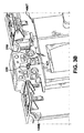
- a motor operator 100 is shown mounted to a circuit breaker 120.
- a circuit breaker 120 the embodiments disclosed will be described with reference to the drawings, it should be understood that the embodiments disclosed can be embodied in many alternate forms. In addition, any suitable size, shape or type of elements or materials could be used. It is also noted that while the exemplary embodiments are described herein with respect to motor operator 100, it should be understood that the exemplary embodiments may be equally applied to any suitable accessory device for circuit breakers.
- the exemplary embodiments provide a user friendly motor operator design that allows for easy installation of the motor operator 100 to a circuit breaker 120 where the circuit breaker 120 and motor operator 100 are in a substantially vertical orientation, such as when mounted on a wall.
- the motor operator 100 and circuit breaker 120 include complimentary guiding features that allow a spring-biased pin 330 ( Fig. 3A ) of the motor operator 100 to engage a lock receiving aperture 200 ( Fig. 2 ) of the circuit breaker as will be described in greater detail below. Engagement of the motor operator pin 330 with the lock receiving aperture 200 secures the motor operator 100 to the circuit breaker 120.
- one or more of the installer's hands may be free from holding the motor operator 100 on the circuit breaker 120, allowing the installer to complete the installation of the motor operator to the circuit breaker without fear of the motor operator falling away from or off of the circuit breaker.
- the motor operator 100 includes a base plate 100B and a top portion 100T.
- the top portion 100T includes a housing 100H and a motor operator frame (not shown).
- the motor operator frame may be part of or integral to a motor operator mechanism (not shown).
- the motor operator frame may be configured so that the motor operator mechanism can be mounted to the frame.
- the motor operator mechanism and the motor operator frame are substantially housed within the housing 100H and the housing 100H is mounted to the motor operator frame in any suitable manner.
- the top portion 100T may be hingably mounted to the base plate 100B in any suitable manner, such as through the motor operator frame so that the top portion 100T is pivotable about the hinge in the direction of arrow E to allow access to motor operator mechanism and/or to allow mounting of the motor operator 100 to the circuit breaker 120.
- the motor operator 100 may be mounted to the circuit breaker 120 in any suitable manner.
- the circuit breaker 120 and motor operator 100 may include complementary features that facilitate mounting the motor operator 100 to the circuit breaker 120.
- the circuit breaker 120 includes a housing 120H.
- the housing 120H includes a recess 220 through which the circuit breaker handle 210 protrudes.
- the recess 220 may have surfaces 220A, 220B, 220C.
- the circuit breaker housing 120H may also include a surface 230 that may be formed at an angle relative to surface 220A so as to form a wedge shaped interface between the surfaces 220A, 230.
- the surface 230 may include a lock receiving aperture 200 that allows a pin 330 of a locking mechanism ( Fig. 4A-4C ) to pass through the housing 120H into the lock receiving aperture 200.
- the pin 330 may also pass through the housing and into an aperture 460 in plate 350P ( Figs. 4A, 4B ) as will be described below.
- the plate 350P may be suitably mounted to, for example, the frame 350 of a circuit breaker trip unit mechanism 350M.
- the frame 350 includes side members 350L to which the plate 350P is fixedly secured.
- a plate may be integrally formed in or affixed to the housing 120H where the plate includes an aperture for accepting the pin 330 in a manner substantially similar to that described herein with respect to plate 350P.
- the motor operator base plate 100B may have a top side 400T and a bottom side 400B.
- the top portion 100T of the motor operator 100 may be hingably mounted to the top side 400T of the base plate 100B.
- the bottom side 400B of the base plate 100B contacts the circuit breaker housing 120H when the motor operator is mounted to the circuit breaker 120.
- the base plate 100B may include a protrusion 410 extending from the bottom side 400B of the base plate 100B.
- the protrusion 410 may be suitably configured such that the protrusion has a shape substantially complimentary to the recess 220 in the circuit breaker housing 120H.
- the protrusion 410 may include surfaces 410A, 410B, 410C that are suitably shaped to substantially contact surfaces 220A, 220B, 220C of the recess 220 and allow the at least a portion of the bottom side 400B of the base plate 100B to substantially seat against the circuit breaker housing 120H for mounting the base plate 100B (and thus the motor operator 100) to the circuit breaker 120.
- Surface 410A may be configured to substantially contact surface 220A
- surface 410B may be configured to substantially contact surface 220B
- surface 410C may be configured to substantially contact surface 220C.
- the protrusion 410 is sized to that it may be slip fit into the recess 220. In other examples the fit between the protrusion 410 and recess 220 may be an interference fit.
- the bottom side 400B of the base plate 100B may also include a surface 420 from which a portion of the pin 330 protrudes.
- the surface 420 may be formed at an angle with surface 410A so as to form a substantially wedge shaped interface between the surfaces 410A, 420.
- the surface 420 may also be substantially parallel with surface 230 of the circuit breaker housing 120H when the motor operator 100 is mounted to the circuit breaker 120.
- the surface 420 may substantially contact the surface 230 such that when the motor operator 100 is mounted on the circuit breaker 120 the protrusion 410 interacts with the recess 220 and/or the surface 420 interacts with surface 230 for guiding the base plate 100B onto the circuit breaker housing 120H for substantially aligning the pin 330 of the locking mechanism 300 ( Figs. 4A-4C ) with the lock receiving aperture 200 as described in greater detail below.
- the top side 400T of the base plate 100B may include a surface 420 through which a portion of the pin 330 protrudes.
- the surface 420 may be substantially parallel with surface 420 located on the bottom side of the base plate 100B. In other examples, the surfaces through which the pin protrudes may have any suitable orientation relative to each other.
- the locking mechanism 300 passes through an aperture 100A in the motor operator base plate 100B.
- the aperture may be a stepped aperture having a first diameter A and a second diameter B which is smaller than the first diameter A.
- the first diameter A opens through the bottom side 400B of the base plate 100B while the second diameter B opens through top side 400T of the base plate 100B.
- the transition between the first and second diameters A, B within the aperture 100A forms a step or shoulder 100S.
- the locking mechanism 300 includes pin 330, spring 340, plate 310 and a locking device 320.
- the pin 330 is a step pin including at least a first diameter 330A adjacent a first end 330E1 of the pin 330 and a second diameter 330B adjacent a second end 330E2 of the pin 330.
- the first diameter 330A is suitably sized to fit within the first diameter A of aperture 100A.
- the second diameter 330B of the pin 330 is suitably sized to fit within the second diameter B of the aperture 100A. Suitable clearance exists between the pin 330 diameters 330A, 330B and the aperture 100A diameters A, B for allowing the pin 330 to move in the direction of arrow D within the aperture 100A.
- the transition between the first diameter 330A and the second diameter 330B of the pin 330 forms a step or shoulder 330S.
- the pin may have any suitable configuration.
- the plate 310 may be a stepped plate having a base portion 310B and an extension portion 310E.
- the bottom surface 435 of the extension portion 310E is offset from the bottom surface 430 of the base portion 310B so as to form step C.
- the base portion 310B also includes an aperture 310A through which the pin 330 passes.
- the diameter of the aperture 310A may be substantially the same diameter as the second diameter 330B of the pin.
- the aperture 310A may have a slip fit over the second diameter 330B of the pin 330 while in other examples, the fit between the aperture 310A and the second diameter 330B may be an interference fit.
- the spring 340 is placed over the pin 330 and the pin is inserted into the aperture 100A so that the spring is sandwiched between the shoulder 100S of the aperture 100A and the shoulder 330S of the pin 330.
- the spring 340 is configured to bias the pin 330 so that the first end 330E1 of the pin 330 protrudes from the aperture 100A past surface 420 of the base plate 100B (see also Fig. 3A ).
- the second end 330E2 of the pin protrudes through the second diameter B of the aperture so that the second end 330E2 extends past the surface 421 on the top side 400T of the base plate 100B.
- the plate 310 is placed onto the second end 330E2 of the pin 330 so that the second end passes at least partially through aperture 310A in the plate 310.
- a locking device 320 is affixed to the second end of the pin 330E2 for preventing the pin 330 from escaping the aperture 310A.
- the locking device 320 may be any suitable device such as, for example, a clip that engages a recess or groove 450 in the pin 330 or a fastener that engages threads 455 formed in (e.g. internal threads) or on (e.g. external threads) the pin 330.
- the locking device 320 may effect capturing the locking mechanism 300 in the base plate 100B.
- the biasing force of the spring 340 causes the bottom surface 430 of the base portion 310B of the plate 310 to contact surface 421 on the top side 400T of the base plate 100B for capturing the locking mechanism 300 within base plate 100B.
- FIG. 2 , 3A and 4A an exemplary installation of the motor operator 100 on the circuit breaker 120 will now be described.
- An installer places the motor operator base plate 100B against the housing 120H of the circuit breaker 120 so that the protrusion 410 of the base plate 100B is substantially inserted into the recess 220 of the circuit breaker 120.
- the surface 420 of the base plate 100B also substantially contacts the surface 230 of the housing 120H.
- the surfaces 410 and 420 and the surfaces 220, 230 are angled relative to each other so as to form mating wedges (as shown in Fig. 4A were one wedge fits in the other wedge).
- the pin 330 contacts surface 230 such that the pin is forced into the aperture 100A.
- the protrusion 410, recess 220 and/or surfaces 420, 230 guide placement of the base plate 100B so that the first end 33E of the pin is substantially aligned with the lock receiving aperture 200.
- the spring 340 forces the first end 330E of the pin 330 into the lock receiving aperture 200 and into the aperture 460 of plate 350P.
- the pin 330 when located within the lock receiving aperture 200, secures the motor operator 100 from falling away from the circuit breaker while at least a portion of the wedge shape interfaces formed by one or more of the surfaces 410, 420 and 220, 230 in conjunction with the pin 300 being engaged in the apertures 200, 460 substantially prevents the pin 330 from being lifted out of the lock receiving aperture 200.
- the locking mechanism 300 secures the motor operator from falling away from or being lifted off of the circuit breaker, one or more of the installer's hands are free to secure the motor operator 100 to the circuit breaker 120 using any suitable fasteners and any necessary tools.
- the locking mechanism is also configured to allow easy removal of the motor operator 100 from the circuit breaker 120.
- the installer may use one or more hands to remove the fasteners securing the motor operator 100 to the circuit breaker 120.
- the installer may then release the locking mechanism 300 by lifting or otherwise removing the pin 330 from the apertures 200, 460.
- the pin 330 may be removed from the apertures 200, 460 by placing an object between the surface 421 of the base plate 100B and the bottom surface 435 of the plate extension 310E for effectively pulling the pin 330 out of the apertures 200, 460.
- the locking mechanism 300 may be configured so that the installer presses the plate extension 310E towards the surface 421 so the plate 310 acts as a cam (e.g. pivoting about point P in Fig. 4C ) for removing the pin 330 from the apertures 200, 460.
- the pin 330 may be removed from the aperture 200, 460 in any suitable manner.
Landscapes
- Breakers (AREA)
Applications Claiming Priority (1)
| Application Number | Priority Date | Filing Date | Title |
|---|---|---|---|
| US12/425,443 US8178806B2 (en) | 2009-04-17 | 2009-04-17 | Device for mounting an accessory device to a circuit breaker |
Publications (3)
| Publication Number | Publication Date |
|---|---|
| EP2242079A2 true EP2242079A2 (fr) | 2010-10-20 |
| EP2242079A3 EP2242079A3 (fr) | 2013-07-10 |
| EP2242079B1 EP2242079B1 (fr) | 2018-01-10 |
Family
ID=42261953
Family Applications (1)
| Application Number | Title | Priority Date | Filing Date |
|---|---|---|---|
| EP10159974.4A Not-in-force EP2242079B1 (fr) | 2009-04-17 | 2010-04-15 | Dispositif pour assembler un dispositif accessoire sur un disjoncteur |
Country Status (3)
| Country | Link |
|---|---|
| US (1) | US8178806B2 (fr) |
| EP (1) | EP2242079B1 (fr) |
| CN (1) | CN101866784B (fr) |
Family Cites Families (12)
| Publication number | Priority date | Publication date | Assignee | Title |
|---|---|---|---|---|
| NL300256A (fr) * | 1962-11-08 | |||
| US4245140A (en) * | 1979-06-25 | 1981-01-13 | General Electric Company | Manual and motor operated circuit breaker |
| US4804809A (en) * | 1987-10-26 | 1989-02-14 | A. B. Chance Company | Motor operator for padmount switchgear |
| US5302786A (en) * | 1992-10-19 | 1994-04-12 | General Electric Company | Molded case circuit breaker for remote control operations |
| FR2701617B1 (fr) * | 1993-02-16 | 1995-04-14 | Merlin Gerin | Disjoncteur à télécommande et à fonction de sectionnement. |
| US5428196A (en) * | 1994-03-01 | 1995-06-27 | Eaton Corporation | Flexible shaft interface for circuit interrupter |
| US6072132A (en) * | 1999-09-28 | 2000-06-06 | Eaton Corporation | Apparatus for mounting a motor operator on a circuit |
| SE517731C2 (sv) * | 2000-02-03 | 2002-07-09 | Abb Ab | Elektrisk brytare, elektrisk anläggning, användning av elektrisk brytare och förfarande för brytning av elektrisk ström |
| US6806800B1 (en) * | 2000-10-19 | 2004-10-19 | General Electric Company | Assembly for mounting a motor operator on a circuit breaker |
| US6495781B2 (en) * | 2000-12-27 | 2002-12-17 | General Electric Company | Handle position indicator |
| US6945780B2 (en) * | 2001-04-02 | 2005-09-20 | United Defense, L.P. | Integrated performance simulation system for military weapon systems |
| CN201107802Y (zh) * | 2007-06-08 | 2008-08-27 | 刘新广 | 永磁开合式断路器 |
-
2009
- 2009-04-17 US US12/425,443 patent/US8178806B2/en not_active Expired - Fee Related
-
2010
- 2010-04-15 EP EP10159974.4A patent/EP2242079B1/fr not_active Not-in-force
- 2010-04-19 CN CN2010101710141A patent/CN101866784B/zh not_active Expired - Fee Related
Non-Patent Citations (1)
| Title |
|---|
| None |
Also Published As
| Publication number | Publication date |
|---|---|
| US8178806B2 (en) | 2012-05-15 |
| US20100264002A1 (en) | 2010-10-21 |
| EP2242079A3 (fr) | 2013-07-10 |
| EP2242079B1 (fr) | 2018-01-10 |
| CN101866784B (zh) | 2013-08-21 |
| CN101866784A (zh) | 2010-10-20 |
Similar Documents
| Publication | Publication Date | Title |
|---|---|---|
| EP1218914B1 (fr) | Disjoncteur a boitier moule avec mecanisme a manette servant a indiquer la circulation du courant | |
| RU2319265C2 (ru) | Аксиальный привод фиксатора | |
| AU766594B2 (en) | Circuit interrupter with improved din rail mounting adaptor | |
| PL199119B1 (pl) | Rozdzielnica niskonapięciowa | |
| CN113972104A (zh) | 一种小体积的模块化的自动分合闸物联网断路器 | |
| WO2001016989A1 (fr) | Interrupteur de circuit avec crossbar a protection de barriere amelioree | |
| US6255926B1 (en) | Circuit interrupter with accessory trip interface and break-away access thereto | |
| US6356175B1 (en) | Circuit interrupter with improved terminal shield and shield cover | |
| US6437671B1 (en) | Circuit interrupter with secure base and terminal connection | |
| EP2242079B1 (fr) | Dispositif pour assembler un dispositif accessoire sur un disjoncteur | |
| US6229419B1 (en) | Circuit interrupter with break-away walking beam access | |
| CA2382854A1 (fr) | Interrupteur de circuit comportant un levier auxiliaire a sonnerie en deux parties avec course excedentaire | |
| US6184763B1 (en) | Circuit interupter with screw retainment | |
| WO2001016980A1 (fr) | Interrupteur possedant une base ayant un support de paroi exterieure et un mecanisme de commande securise ameliore | |
| EP2242071A2 (fr) | Ensemble d'opérateur de moteur | |
| KR20060021486A (ko) | 배선용 차단기 |
Legal Events
| Date | Code | Title | Description |
|---|---|---|---|
| PUAI | Public reference made under article 153(3) epc to a published international application that has entered the european phase |
Free format text: ORIGINAL CODE: 0009012 |
|
| AK | Designated contracting states |
Kind code of ref document: A2 Designated state(s): AT BE BG CH CY CZ DE DK EE ES FI FR GB GR HR HU IE IS IT LI LT LU LV MC MK MT NL NO PL PT RO SE SI SK SM TR |
|
| AX | Request for extension of the european patent |
Extension state: AL BA ME RS |
|
| PUAL | Search report despatched |
Free format text: ORIGINAL CODE: 0009013 |
|
| AK | Designated contracting states |
Kind code of ref document: A3 Designated state(s): AT BE BG CH CY CZ DE DK EE ES FI FR GB GR HR HU IE IS IT LI LT LU LV MC MK MT NL NO PL PT RO SE SI SK SM TR |
|
| AX | Request for extension of the european patent |
Extension state: AL BA ME RS |
|
| RIC1 | Information provided on ipc code assigned before grant |
Ipc: F16B 17/00 20060101ALI20130603BHEP Ipc: H01H 71/70 20060101AFI20130603BHEP |
|
| 17P | Request for examination filed |
Effective date: 20140110 |
|
| RBV | Designated contracting states (corrected) |
Designated state(s): AT BE BG CH CY CZ DE DK EE ES FI FR GB GR HR HU IE IS IT LI LT LU LV MC MK MT NL NO PL PT RO SE SI SK SM TR |
|
| GRAP | Despatch of communication of intention to grant a patent |
Free format text: ORIGINAL CODE: EPIDOSNIGR1 |
|
| RIC1 | Information provided on ipc code assigned before grant |
Ipc: H01H 71/70 20060101AFI20170818BHEP Ipc: F16B 17/00 20060101ALI20170818BHEP |
|
| INTG | Intention to grant announced |
Effective date: 20170907 |
|
| RIN1 | Information on inventor provided before grant (corrected) |
Inventor name: POMMERENCKE, LARS Inventor name: RAJAURIA, SAMIR |
|
| GRAS | Grant fee paid |
Free format text: ORIGINAL CODE: EPIDOSNIGR3 |
|
| GRAA | (expected) grant |
Free format text: ORIGINAL CODE: 0009210 |
|
| AK | Designated contracting states |
Kind code of ref document: B1 Designated state(s): AT BE BG CH CY CZ DE DK EE ES FI FR GB GR HR HU IE IS IT LI LT LU LV MC MK MT NL NO PL PT RO SE SI SK SM TR |
|
| REG | Reference to a national code |
Ref country code: GB Ref legal event code: FG4D |
|
| REG | Reference to a national code |
Ref country code: CH Ref legal event code: EP Ref country code: AT Ref legal event code: REF Ref document number: 963272 Country of ref document: AT Kind code of ref document: T Effective date: 20180115 |
|
| REG | Reference to a national code |
Ref country code: IE Ref legal event code: FG4D |
|
| REG | Reference to a national code |
Ref country code: DE Ref legal event code: R096 Ref document number: 602010047891 Country of ref document: DE |
|
| REG | Reference to a national code |
Ref country code: NL Ref legal event code: MP Effective date: 20180110 |
|
| REG | Reference to a national code |
Ref country code: AT Ref legal event code: MK05 Ref document number: 963272 Country of ref document: AT Kind code of ref document: T Effective date: 20180110 |
|
| PG25 | Lapsed in a contracting state [announced via postgrant information from national office to epo] |
Ref country code: NL Free format text: LAPSE BECAUSE OF FAILURE TO SUBMIT A TRANSLATION OF THE DESCRIPTION OR TO PAY THE FEE WITHIN THE PRESCRIBED TIME-LIMIT Effective date: 20180110 |
|
| PG25 | Lapsed in a contracting state [announced via postgrant information from national office to epo] |
Ref country code: FI Free format text: LAPSE BECAUSE OF FAILURE TO SUBMIT A TRANSLATION OF THE DESCRIPTION OR TO PAY THE FEE WITHIN THE PRESCRIBED TIME-LIMIT Effective date: 20180110 Ref country code: NO Free format text: LAPSE BECAUSE OF FAILURE TO SUBMIT A TRANSLATION OF THE DESCRIPTION OR TO PAY THE FEE WITHIN THE PRESCRIBED TIME-LIMIT Effective date: 20180410 Ref country code: HR Free format text: LAPSE BECAUSE OF FAILURE TO SUBMIT A TRANSLATION OF THE DESCRIPTION OR TO PAY THE FEE WITHIN THE PRESCRIBED TIME-LIMIT Effective date: 20180110 Ref country code: ES Free format text: LAPSE BECAUSE OF FAILURE TO SUBMIT A TRANSLATION OF THE DESCRIPTION OR TO PAY THE FEE WITHIN THE PRESCRIBED TIME-LIMIT Effective date: 20180110 Ref country code: LT Free format text: LAPSE BECAUSE OF FAILURE TO SUBMIT A TRANSLATION OF THE DESCRIPTION OR TO PAY THE FEE WITHIN THE PRESCRIBED TIME-LIMIT Effective date: 20180110 Ref country code: CY Free format text: LAPSE BECAUSE OF FAILURE TO SUBMIT A TRANSLATION OF THE DESCRIPTION OR TO PAY THE FEE WITHIN THE PRESCRIBED TIME-LIMIT Effective date: 20180110 |
|
| PG25 | Lapsed in a contracting state [announced via postgrant information from national office to epo] |
Ref country code: GR Free format text: LAPSE BECAUSE OF FAILURE TO SUBMIT A TRANSLATION OF THE DESCRIPTION OR TO PAY THE FEE WITHIN THE PRESCRIBED TIME-LIMIT Effective date: 20180411 Ref country code: BG Free format text: LAPSE BECAUSE OF FAILURE TO SUBMIT A TRANSLATION OF THE DESCRIPTION OR TO PAY THE FEE WITHIN THE PRESCRIBED TIME-LIMIT Effective date: 20180410 Ref country code: IS Free format text: LAPSE BECAUSE OF FAILURE TO SUBMIT A TRANSLATION OF THE DESCRIPTION OR TO PAY THE FEE WITHIN THE PRESCRIBED TIME-LIMIT Effective date: 20180510 Ref country code: PL Free format text: LAPSE BECAUSE OF FAILURE TO SUBMIT A TRANSLATION OF THE DESCRIPTION OR TO PAY THE FEE WITHIN THE PRESCRIBED TIME-LIMIT Effective date: 20180110 Ref country code: SE Free format text: LAPSE BECAUSE OF FAILURE TO SUBMIT A TRANSLATION OF THE DESCRIPTION OR TO PAY THE FEE WITHIN THE PRESCRIBED TIME-LIMIT Effective date: 20180110 Ref country code: LV Free format text: LAPSE BECAUSE OF FAILURE TO SUBMIT A TRANSLATION OF THE DESCRIPTION OR TO PAY THE FEE WITHIN THE PRESCRIBED TIME-LIMIT Effective date: 20180110 Ref country code: AT Free format text: LAPSE BECAUSE OF FAILURE TO SUBMIT A TRANSLATION OF THE DESCRIPTION OR TO PAY THE FEE WITHIN THE PRESCRIBED TIME-LIMIT Effective date: 20180110 |
|
| REG | Reference to a national code |
Ref country code: DE Ref legal event code: R097 Ref document number: 602010047891 Country of ref document: DE |
|
| PG25 | Lapsed in a contracting state [announced via postgrant information from national office to epo] |
Ref country code: IT Free format text: LAPSE BECAUSE OF FAILURE TO SUBMIT A TRANSLATION OF THE DESCRIPTION OR TO PAY THE FEE WITHIN THE PRESCRIBED TIME-LIMIT Effective date: 20180110 Ref country code: RO Free format text: LAPSE BECAUSE OF FAILURE TO SUBMIT A TRANSLATION OF THE DESCRIPTION OR TO PAY THE FEE WITHIN THE PRESCRIBED TIME-LIMIT Effective date: 20180110 Ref country code: EE Free format text: LAPSE BECAUSE OF FAILURE TO SUBMIT A TRANSLATION OF THE DESCRIPTION OR TO PAY THE FEE WITHIN THE PRESCRIBED TIME-LIMIT Effective date: 20180110 |
|
| PLBE | No opposition filed within time limit |
Free format text: ORIGINAL CODE: 0009261 |
|
| STAA | Information on the status of an ep patent application or granted ep patent |
Free format text: STATUS: NO OPPOSITION FILED WITHIN TIME LIMIT |
|
| PG25 | Lapsed in a contracting state [announced via postgrant information from national office to epo] |
Ref country code: CZ Free format text: LAPSE BECAUSE OF FAILURE TO SUBMIT A TRANSLATION OF THE DESCRIPTION OR TO PAY THE FEE WITHIN THE PRESCRIBED TIME-LIMIT Effective date: 20180110 Ref country code: MC Free format text: LAPSE BECAUSE OF FAILURE TO SUBMIT A TRANSLATION OF THE DESCRIPTION OR TO PAY THE FEE WITHIN THE PRESCRIBED TIME-LIMIT Effective date: 20180110 Ref country code: SM Free format text: LAPSE BECAUSE OF FAILURE TO SUBMIT A TRANSLATION OF THE DESCRIPTION OR TO PAY THE FEE WITHIN THE PRESCRIBED TIME-LIMIT Effective date: 20180110 Ref country code: SK Free format text: LAPSE BECAUSE OF FAILURE TO SUBMIT A TRANSLATION OF THE DESCRIPTION OR TO PAY THE FEE WITHIN THE PRESCRIBED TIME-LIMIT Effective date: 20180110 Ref country code: DK Free format text: LAPSE BECAUSE OF FAILURE TO SUBMIT A TRANSLATION OF THE DESCRIPTION OR TO PAY THE FEE WITHIN THE PRESCRIBED TIME-LIMIT Effective date: 20180110 |
|
| REG | Reference to a national code |
Ref country code: CH Ref legal event code: PL |
|
| 26N | No opposition filed |
Effective date: 20181011 |
|
| REG | Reference to a national code |
Ref country code: BE Ref legal event code: MM Effective date: 20180430 |
|
| GBPC | Gb: european patent ceased through non-payment of renewal fee |
Effective date: 20180415 |
|
| REG | Reference to a national code |
Ref country code: IE Ref legal event code: MM4A |
|
| PG25 | Lapsed in a contracting state [announced via postgrant information from national office to epo] |
Ref country code: LU Free format text: LAPSE BECAUSE OF NON-PAYMENT OF DUE FEES Effective date: 20180415 |
|
| PG25 | Lapsed in a contracting state [announced via postgrant information from national office to epo] |
Ref country code: GB Free format text: LAPSE BECAUSE OF NON-PAYMENT OF DUE FEES Effective date: 20180415 Ref country code: BE Free format text: LAPSE BECAUSE OF NON-PAYMENT OF DUE FEES Effective date: 20180430 Ref country code: SI Free format text: LAPSE BECAUSE OF FAILURE TO SUBMIT A TRANSLATION OF THE DESCRIPTION OR TO PAY THE FEE WITHIN THE PRESCRIBED TIME-LIMIT Effective date: 20180110 Ref country code: CH Free format text: LAPSE BECAUSE OF NON-PAYMENT OF DUE FEES Effective date: 20180430 Ref country code: LI Free format text: LAPSE BECAUSE OF NON-PAYMENT OF DUE FEES Effective date: 20180430 |
|
| PG25 | Lapsed in a contracting state [announced via postgrant information from national office to epo] |
Ref country code: FR Free format text: LAPSE BECAUSE OF NON-PAYMENT OF DUE FEES Effective date: 20180430 Ref country code: IE Free format text: LAPSE BECAUSE OF NON-PAYMENT OF DUE FEES Effective date: 20180415 |
|
| PGFP | Annual fee paid to national office [announced via postgrant information from national office to epo] |
Ref country code: DE Payment date: 20190418 Year of fee payment: 10 |
|
| PG25 | Lapsed in a contracting state [announced via postgrant information from national office to epo] |
Ref country code: MT Free format text: LAPSE BECAUSE OF NON-PAYMENT OF DUE FEES Effective date: 20180415 |
|
| PG25 | Lapsed in a contracting state [announced via postgrant information from national office to epo] |
Ref country code: TR Free format text: LAPSE BECAUSE OF FAILURE TO SUBMIT A TRANSLATION OF THE DESCRIPTION OR TO PAY THE FEE WITHIN THE PRESCRIBED TIME-LIMIT Effective date: 20180110 |
|
| PG25 | Lapsed in a contracting state [announced via postgrant information from national office to epo] |
Ref country code: PT Free format text: LAPSE BECAUSE OF FAILURE TO SUBMIT A TRANSLATION OF THE DESCRIPTION OR TO PAY THE FEE WITHIN THE PRESCRIBED TIME-LIMIT Effective date: 20180110 Ref country code: HU Free format text: LAPSE BECAUSE OF FAILURE TO SUBMIT A TRANSLATION OF THE DESCRIPTION OR TO PAY THE FEE WITHIN THE PRESCRIBED TIME-LIMIT; INVALID AB INITIO Effective date: 20100415 |
|
| PG25 | Lapsed in a contracting state [announced via postgrant information from national office to epo] |
Ref country code: MK Free format text: LAPSE BECAUSE OF NON-PAYMENT OF DUE FEES Effective date: 20180110 |
|
| REG | Reference to a national code |
Ref country code: DE Ref legal event code: R081 Ref document number: 602010047891 Country of ref document: DE Owner name: ABB SCHWEIZ AG, CH Free format text: FORMER OWNER: GENERAL ELECTRIC CO., SCHENECTADY, N.Y., US |
|
| REG | Reference to a national code |
Ref country code: DE Ref legal event code: R119 Ref document number: 602010047891 Country of ref document: DE |
|
| PG25 | Lapsed in a contracting state [announced via postgrant information from national office to epo] |
Ref country code: DE Free format text: LAPSE BECAUSE OF NON-PAYMENT OF DUE FEES Effective date: 20201103 |